A Simple Numerical Solution Method for TM Scattering by
Conducting Cylinders Partially Buried in a Dielectric Half-Space
Cengiz Ozzaim*
Abstract—The scattering of a transverse magnetic plane wave by a conducting cylinder partially buried in a dielectric half-space is solved by an aperture method. A system of coupled integral equations for the current induced on the cylinder and the scattered electric field at the dielectric interface are formulated from field equivalence principles. The scattered tangential electric field at interface is negligible at some distance from the cylinder location. Hence, for a sufficiently wide interface truncation, the coupled integral equations can be easily solved numerically by the Method of Moments. Data for the cylinder current, the scattered electric field at interface and the far-zone field are shown for cases of interest.
1. INTRODUCTION
The problem of plane wave scattering from a conducting cylinder partially buried in a dielectric half-space has been studied extensively due to the applications in geophysical explorations, remote sensing, near field optics, etc. Some investigators have analyzed the scattering from two-dimensional [1–6] and three-dimensional [7–9] objects partially buried in a dielectric half-space or straddling several layers in a multilayered background. Most of the past research requires the computation of Sommerfeld integrals. In some recent work, the dielectric interface has been considered as a scatterer, and free space operators are used in coupled integral equations to compute the scattering from objects partially embedded in a dielectric half-space [10, 11]. In the numerical solution of these formulations, the infinite interface is truncated, and hence the interface is treated as a finite dielectric object. Recently, dielectric and/or conducting cylinders disjoint from the interface are investigated by treating the interface as an infinite aperture [12–14]. In the present paper, partially buried conducting cylinders are considered, whereas in the former, attention is limited to a conducting and a dielectric cylinder buried entirely in one of the half-spaces [12–14]. In the proposed method, the flat dielectric interface is represented by a perturbed equivalent magnetic current. The perturbed current is the difference between the currents on the interface with and without the cylinder present. Since the difference equivalent magnetic current representing the interface decays at some distance from the cylinder location, the interface is truncated, and hence the integral equations can be easily solved by the Method of Moments (MoM).
2. INTEGRAL EQUATIONS
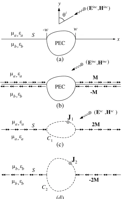
A perfectly electrically conducting (PEC) cylinder of general cross section partially buried in a dielectric half-space is shown in Fig. 1(a). The excitation is a time harmonic transverse magnetic (TM) plane wave in the upper region defined by
Einc= ˆz E
0ejka(xsinθ
i+ycosθi)
. (1)
Received 26 September 2019, Accepted 19 November 2019, Scheduled 7 December 2019 * Corresponding author: Cengiz Ozzaim ([email protected]).
M
x y
Pa Ha
J1
C1
-2M -M
(a)
(b)
(c)
(d)
Ti
PEC PEC
J2
C 2 S
-w w
(Einc ,Hinc )
S
,
Pb,Hb
Einc,Hinc
( )
Pa Ha
(Esc ,Hsc )
,
Pb,Hb
2M
P
a Ha
,
Pa,Ha
S
P
b Hb
,
Pb,Hb
Figure 1. (a) Original problem, (b) interface shorted, (c) equivalent model above interface, (d) equivalent model below interface.
According to the field equivalence principle, we short the interface denoted by S, where S is defined by y = 0 plane when |x| > w. Equivalent magnetic current sheets of equal amplitudes but opposite signs are placed on either side ofS as seen in Fig. 1(b). By this procedure, continuity of the tangential electric field at the interface is automatically satisfied. Using the image theory, this equivalent model is divided into two sub problems for the upper and lower regions. An equivalent model valid above the interface is shown in Fig. 1(c). The total fields in the upper region can be written as
Ea = Ea(2M) +Ea(J1) +Esc+Ea(2MP O)−Ea(2MP O) (2)
Ha = Ha(2M) +Ha(J1) +Hsc+Ha(2MP O)−Ha(2MP O) (3)
The fields, (Esc,Hsc), in Eqs. (2) and (3) are the short circuit fields due to the plane wave in the presence of the shorted interface. MP O in above equations represents the magnetic current at interface corresponding to the case when the cylinder is removed. The current MP O is defined on y = 0 plane when −∞ < x < ∞. The fields due to MP O are added to and subtracted from above equations to enable one to define a difference equivalent magnetic current as MP =M−MP O+MA. Note that
MP is defined on the same surface asM (i.e., when|x|> w). Notice also that MA is the current strip defined asMA=MP O when|x| ≤w. UnlikeMandMP O, the difference currentMP decays rapidly as |x|gets large. The total fields valid above the interface can now be written in terms of MP and MA as
Ea = Ea2MP+Ea(J
1) +Esc+Ea
2MP O−Ea2MA (4)
Ha = Ha2MP+Ha(J1) +Hsc+Ha
2MP O−Ha2MA (5)
The equivalent problem for the lower half-space is shown in Fig. 1(d). Similarly, the total fields in this region can easily be written in terms of MP and MA as
Eb=Eb(−2MP) +Eb(J
Hb =Hb(−2MP) +Hb(J
2) +Hb(−2MP O)−Hb(−2MA) (7)
Enforcing the continuity of the tangential magnetic field across the dielectric interface and forcing the tangential component of the electric fields to vanish on C1 and C2 result in the following system of
equations.
Ha2MP+Hb2MP+Ha(J
1)−Hb(J2)
tan =
Ha2MA+Hb2MA
tan on S (8)
Ea2MP+Ea(J
1)
tan =
Ea2MA−Esc−Ea2MP O
tan on C1(9)
Eb2MP−Eb(J2)
tan =
Eb2MA−Eb2MP O
tan on C2 (10)
Equation (8) is obtained using the following auxiliary equation when the conducting cylinder is removed.
Hsc+Ha(2MP O)tan =Hbtan(−2MP O) on S (11)
The termEsc+Ea2MP Oin Eq. (9) is the total electric field and its image in the upper half-space in the absence of the cylinder. The term Eb(2MP O) in Eq. (10) is the transmitted electric field and its image in the lower half-space when the cylinder is removed. The solutions to these terms are determined analytically in closed form. The fields due to MAin Eqs. (8)–(10) can be computed easily since MAis known (MA=MP O). SinceMP decays rapidly as|x|becomes large, one can truncate the limits of the integral operators. By this assumption, the coupled integral equations can be easily solved numerically by the MoM. We also note that the scattered field valid in the upper half-space is computed by the superposition of 2MP, J1, and−2MA while it is computed in the lower half-space by −2MP, J2 and
2MA.
3. NUMERICAL RESULTS
Data for the perturbed equivalent magnetic current or equivalently the scattered electric field at interface, the current induced on the cylinder and the far-zone scattered field are illustrated in this section. In the following numerical experiments, the region above the interface is considered air, and both media are assumed lossless and non-magnetic. The MoM solution of the integral equations is implemented in FORTRAN 90, and the surface contours are divided into 10 to 20 segments per wavelength.
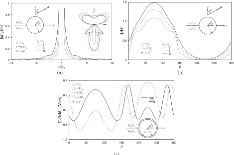
Consider first a half-buried PEC circular cylinder with a radius of half free space wavelength [6]. The scattered electric field at interface and the far-zone scattered field for various regionbpermittivities are shown in Fig. 2(a). Notice that the magnetic sheet of currents decays in about a few free space wavelengths in either direction along the x-axis. The scattered far-field pattern is smooth in the upper region while the part of the field pattern below the interface has sharp lobes at the critical angles. The magnitude of the induced currents are shown in Fig. 2(b) for various regionb permittivities. The currents are normalized with respect to thex-component of the magnetic field on the cylinder surface at θ= 90◦, with the cylinder removed. The magnitude of current at θ= 90◦ decreases as the permittivity of region b is increased. The magnitudes of currents are almost zero at θ = 270◦ (shadow region) for various region bpermittivities. The real and imaginary parts of the scattered near electric field around the periphery of the circular cylinder are shown in Fig. 2(c) for a plane wave of unity strength. The near field compares favorably with the results of a recent work for a similar study [6].
Consider now an electrically small half-buried PEC circular cylinder [1]. The scattered electric field at interface and the far-zone scattered field for various incident angles are shown in Fig. 3(a). Notice that the magnetic currents decay faster than the previous example. This is because of the electrical size of the cylinder. The electric field pattern at interface is symmetric when the cylinder is normally illuminated, but the symmetry is lost when the excitation is not normally incident. The scattered far-field pattern is smooth in the upper region while it has sharp lobes at the critical angles below the interface. The magnitudes of the induced currents are shown in Fig. 3(b) for various incident angles. The cylinder currents are normalized as in the previous example. For a similar study, the cylinder currents compare favorably with the results published in [1, 4, 11].
150 180 210 240 270 300 5 5 4 4 3 3 2 2 1 1 0 A A I R F F M R n B F F
-10 -5 0 5 10
x/λa 0 0.2 0.4 0.6 0.8 1 | M P/ E in c| 2 4 16 Y θi
NAFA
NBFB R
R X
Y
X
0 60 120 180 240 300 360
R 0 0.6 1.2 1.8 | J/ H i| 2 4 16 B F F A A I R F F M R n Y θi
NAFA
NBFB R
R X
(a) (b)
0 60 120 180 240 300 360
R -1.3 -0.8 -0.3 0.2 0.7 E -f ie ld (V /m ) real imag
NAFA
NBFB R
R R A B A A I R R F F F F M M R a n (c)
Figure 2. Half buried PEC cylinder, (a) induced current, (b) interface electric field and scattered far-field, (c) near-field around the periphery.
60 120 150 180 210 240 270 300 2 1.5 1.5 1 1 0.5 0.5 0
-5 -4 -3 -2 -1 0 1 2 3 4 5
x/λa 0 0.3 0.6 0.9 | M
PE/
in c| 0 45 60 deg I R A B A R F F F F M Y θi
NAFA
NBFB R
R X
Y
X
0 60 120 180 240 300 360
R 0 1 2 3 | J/ H i| 0 45 60 A B A R F F F F M deg I R Y θi
NAFA
NBFB R
R X
(a) (b)
Figure 3. Half buried PEC conducting cylinder. (a) Scattered electric fields at interface and scattered far-field, (b) induced current magnitudes.
60 120 150 180 210 240 270 300 1.8 1.6 1.4 1 1.2 1.2 1 1 0.8 0.8 0.6 0.6 0.4 0.4 0.20.2 0
-5 -4 -3 -2 -1 0 1 2 3 4 5
x/λa 0 0.2 0.4 0.6 0.8 | M P/ E in c| 0 45 60 NAFA
NBFB H W R X Y θi A B A A W H F F F F M M deg I R Y X
0 60 120 180 240 300 360
R 0 1 2 3 4 | J/ H i| 0 45 60 deg I R A B A A W H F F F F M M
NAFA
NBFB H
W
R X
Y
θi
(a) (b)
Figure 4. Half buried rectangular cylinder. (a) Scattered electric fields at interface and scattered far-field, (b) induced current magnitudes.
60 120 150 180 210 240 270 300 2 2 1.5 1.5 1 1 0.5 0.5 0
-5 -4 -3 -2 -1 0 1 2 3 4 5
x/λa 0 0.2 0.4 0.6 0.8 1 | M P/ E in c| 2 4 8 16 B F F NAFA
NBFB H W R X Y θi I A A A W H R F F M M n Y X
0 60 120 180 240 300 360
R 0 1 2 3 4 | J/ H i| 2 4 8 16
NAFA
NBFB H
W R X Y θi B F F I A A A W H R F F M M n (a) (b)
Figure 5. Half buried rectangular cylinder. (a) Scattered electric fields at interface and scattered far-field, (b) induced current magnitudes.
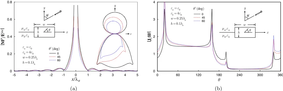
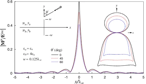
The data presented in Fig. 6 are for a rectangular cylinder, whose one face intersects the interface. The electric field at interface and the far-zone scattered field for various regionbpermittivities when the cylinder is resting right on top of the interface are shown in Fig. 6(a). To obtain these data,J2 and C2
in Eqs. (8)–(10) are eliminated. In Fig. 5(b), the same data are shown for the same cylinder with top face intersecting the interface (i.e., completely buried). To obtain these data,J1 andC1 in Eqs. (8)–(10)
are eliminated. One observes that the fields at interface and the far-fields below the interface are similar for both cases. As the permittivity of the lower medium is increased, the scattered far-field amplitudes above the interface remain almost the same for the case in Fig. 6(a), while they decrease for the case in Fig. 6(b).
60 120 150 180 210 240 270 300 2 2 1.5 1.5 1 1 0.5 0.5 0
-5 -4 -3 -2 -1 0 1 2 3 4 5
x/λa
0 0.3 0.6 0.9 1.2 | M
PE/
in c| 2 4 8 16 B F F I A A A W H R F F M M n NAFA NBFB
H W R X Y θi Y X 150 180 210 240 270 300 2 2 1.5 1.5 1 1 0.5 0.5 0
-5 -4 -3 -2 -1 0 1 2 3 4 5
x/λa 0 0.3 0.6 0.9 1.2 | M P/ E in c| 2 4 8 16 B F F I A A A W H R F F M M n
NAFA
NBFB H
W R X Y θi Y X (a) (b)
Figure 6. Scattered electric fields at interface and scattered far-field for cylinder residing (a) right on top of the interface, (b) bottom of the interface.
-0.25 -0.125 0 0.125 0.25
x/λa
0 2 4 6 | J/ H i| 0 45 60 deg I R A B A A A A W H D R F F F F M M M M Y θi X W W
NAFA
NBFB H
D
R R
0 60 120 180 240 300 360
R 0 0.3 0.6 0.9 | J/ H i| 0 45 60 deg I R A B A A A A W H D R F F F F M M M M Y θi X W W
NAFA
NBFB
H
D R
R
(a) (b)
Figure 7. Coupled cylinders near the interface, (a) induced current on the strip above the interface, (b) current on the circular cylinder below the interface.
150 180 210 240 270 300 1.2 1 1 0.8 0.8 0.6 0.6 0.4 0.4 0.2 0.2 0
-5 -4 -3 -2 -1 0 1 2 3 4 5
x/Oa 0 0.2 0.4 0.6 | M P/ E in c| 0 45 60 deg) ( i T x -w w y Ti H 0.125 a w H H O H y x PaHa
, Pb,Hb
b 0
0
a
4. CONCLUSION
A set of integral equations is presented to compute the scattering from a conducting cylinder partially buried in a dielectric half-space. The convergence of the solution is checked by a few manual iterations in the radius of the truncation. We have found that the radius of truncation is about five wavelengths for objects whose size is less than a quarter-wave. The truncation depends on the electrical size of the object, material parameters, and angle of incidence. The proposed formulation is very simple and relatively efficient for two reasons. First, a single sheet of magnetic current represents the interface between half-spaces, and second, the numerical computations of the half-space Green’s functions involving Sommerfeld integrals are avoided by the use of homogeneous space operators. The approach, even though simpler than other methods, is completely rigorous.
REFERENCES
1. Xu, X.-B. and C. Butler, “Scattering of TM excitation by coupled and partially buried cylinders at the interface between two media,”IEEE Trans. Antennas Propag., Vol. 35, No. 5, 529–538, May 1987.
2. Rao, T. C. and R. Barakat, “Plane-wave scattering by a conducting cylinder partially buried in a ground plane. 1. TM case,”J. Opt. Soc. Amer. A, Vol. 6, No. 9, 1270–1280, Sep. 1989.
3. Marx, E., “Scattering by an arbitrary cylinder at a plane interface: Broadside incidence,” IEEE Trans. Antennas Propag., Vol. 37, No. 5, 619–628, May 1989.
4. Leviatan, Y. and Y. Meyouhas, “Analysis of electromagnetic scattering from buried cylinders using a multifilament current model,” Radio Sci., Vol. 25, No. 6, 1231–1244, Nov. 1990.
5. Ling, R. T. and P. Y. Ufimtsev, “Scattering of electromagnetic waves by a metallic object partially immersed in a semi-infinite dielectric medium,” IEEE Trans. Antennas Propag., Vol. 49, No. 2, 223–233, Feb. 2001.
6. Simsek, E., J. Liu, and Q. H. Liu, “A spectral integral method and hybrid SIM/FEM for layered media,” IEEE Trans. Microw. Theory Techn., Vol. 54, No. 11, 3878–3884, Nov. 2006.
7. Michalski, K. A. and D. Zheng, “Electromagnetic scattering and radiation by surfaces of arbitrary shape in layered media. II. Implementation and results for contiguous half-spaces,” IEEE Trans. Antennas Propag., Vol. 38, No. 3, 345–352, Mar. 1990.
8. Chen, Y. P., W. C. Chew, and L. Jiang, “A new Green’s function formulation for modeling homogeneous objects in layered medium,” IEEE Trans. Antennas Propag., Vol. 60, No. 10, 4766– 4776, Oct. 2012.
9. Luo, W., Z. Nie, and Y. P. Chen, “Efficient higher-order analysis of electromagnetic scattering by objects above, below, or straddling a half-space,” IEEE Antennas Wireless Propag. Lett., Vol. 15, 332–335, 2016.
10. Qi, X., Z. P. Nie, and X. F. Que, “An efficient method for analysis of EM scattering from objects straddling the interface of a half-space,” IEEE Geosci. Remote Sens. Lett., Vol. 13, No. 12, 2014– 2018, Dec. 2016.
11. Kizilay, A. and U. Saynak, “Scattering from a conducting cylinder partially buried in a dielectric half space by a decomposition method,”MIKON, 2016.
12. Ozzaim, C., “Plane wave scattering by a conducting cylinder located near an interface between two dielectric half-spaces: a perturbation method,”IEEE Trans. Antennas Propag., Vol. 65, No. 5, 2754–2758, May 2017.
13. Ozzaim, C., “A perturbation method for scattering by a dielectric cylinder buried in a half-space,”
IEEE Trans. Antennas Propag., Vol. 66, No. 10, 5662–5665, Oct. 2018.