A Novel Triple-Band Filter Based on Triple-Mode Substrate
Integrated Waveguide
Huanying Wang, Guohui Li*, Yudan Wu, Wei Yang, and Tong Mou
Abstract—A novel triple-band filter using triple-mode substrate integrated waveguide (SIW) resonator is presented in this paper. The proposed resonator consists of a square cavity with two additional metallic vias that split the first pair of degenerate modes (TE201 and TE102) at the diagonal of the cavity. Triple-band response is achieved by TE101, TE201and TE102. The center frequencies of the first band and the third band can be controlled by appropriately adjusting the location of perturbation vias, while the second band keeps almost unchanged. A two-pole triple-band filter with two transmission zeros utilizing the coupled triple mode cavity resonators is designed and fabricated. The measured results agree very well with the simulated ones.
1. INTRODUCTION
Microwave filters play an important role in the communication system. Modern communications require microwave filters with small size, low cost, high power capability and high performance, such as high selectivity, low insertion loss, sharp skirt behavior and spurious characteristics. Multi-band SIW filter perfectly satisfies these requirements. In the past years, most of the researchers focused on the realization of microstrip dual-band and triple-band filters based on SIR structure [1–4]. Many of these filters are designed by multi-mode [4]. Moreover, a conventional approach in triple-mode filter designs is based on the degenerate modes of a cavity. In [5], a triple-mode filter using TE101/TE011/TM110 modes in a cubic cavity was proposed. However, this is a band-pass filter with a single band. Few triple-band filters using SIW cavities with multi-mode have been reported.
The properties of low cost, high Q-factor, compact size and easy manufacture make SIW technology attractive for planar filter design by using planar circuit fabrication process. Since SIW is a three-dimensional periodic structure, it has the ability to control the transmission path of electromagnetic waves by metal vias on the dielectric substrate. In a certain range it can replace rectangular metal waveguide [6–9]. This concept was first proposed by a Japanese scholar Shigeki in 1994 [10]. In 1998, Uchimura et al. studied this waveguide structure systematically and fully [11]. Thereafter, many scholars have done a lot of deep researches about SIW.
Recently, the study about dual-mode resonators based on SIW is increasing [12–15], and most of them utilized the high-order resonances of SIW cavity (TE201 and TE102). The filter designed by this method has poor rejection, because TE101 mode in lower frequency is near the first degenerate modes. In this paper, a novel method for designing a substrate integrated waveguide triple-mode triple-band filter is presented, and the triple-band response is achieved by TE101 mode and the first degenerate modes (TE201 and TE102). A perturbation method by placing two additional vias at the diagonal of a square dual-mode SIW cavity resonator is designed to adjust the resonant frequencies of two modes while keeping the resonant frequency of the other mode unchanged. The perturbation splits the first
Received 26 October 2015, Accepted 14 December 2015, Scheduled 2 January 2016
* Corresponding author: Guohui Li ([email protected]).
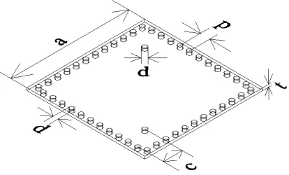
the side length and height of the cavity, respectively,pis the distance between the center of two adjacent vias, cis the distance from the center of the perturbation vias to the nearest sides of the square.
Figure 1. Structure of the square SIW cavity.
2.2. Property of the Perturbation
(a) (b) (c)
Figure 2. Electric field distributions of the mode TE101 and the first degenerate modes, (a) mode TE101, (b) mode TE201, (c) mode TE102.
6 7 8 9 10 11 12 13
-40 -30 -20 -10 0
(a) (b)
0 1 2 3 4 5 6 7 8
c (mm)
5 6 7 8 9 10 11 12
Frequency (GHz)
Frequency (GHz)
S
(dB)
21
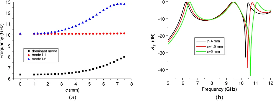
dominant mode mode l-1 mode l-2
c=4 mm c=4.5 mm c=5 mm
Figure 3. (a) Resonant frequencies versus vias’ position c, (b) simulated transmission coefficients against frequency of the square SIW.
3. DESIGN OF THE TRIPLE-MODE TRIPLE-BAND SIW FILTER
To demonstrate the application of the proposed triple-mode square SIW resonator, a bandpass filter with two resonators is investigated. Fig. 4 shows the proposed triple-band SIW filter working at 6.4 GHz, 9.8 GHz, 10.7 GHz. The 50 Ω microstrip lines are transited to the SIW through coplanar waveguide (CPW) structures at the input and output ports. And the width of the port isWs. There are two vias in each cavity which are splitting the first degenerate mode. Two square cavities are coupled to each other through a coupling window, whose size is W12. To get strong coupling, the aperture should be placed to ensure that more energy is allowed to transfer through the aperture as possible. L andW are the length and width of the SIW filter, and Wls and Lsot are the width and length of the gap of the coplanar waveguide, respectively.
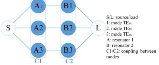
Figure 5 shows the transversal coupling scheme of the proposed filter based on the fundamental mode and the first splitting degenerate mode of the perturbed cavity, where empty circles S and L in this scheme represent the source and load, respectively. Three modes in each resonator are adopted to couple with those in another resonator. For simplicity, only three couplings are considered by ignoring the minor couplings, for example: coupling between TE201mode and TE102 mode. As shown in Fig. 5, three separate paths from source to load are provided. These three paths, corresponding to the lower, middle and higher bands of the triple band filter, respectively, can be easily designed and realized.
Figure 4. Configuration of the proposed triple-mode triple-band SIW filter.
Figure 5. Coupling scheme of the triple-mode triple-band SIW filter.
Table 1. The design specifications of triple-band SIW filter.
f0 (GHz) Bandwidth (MHz) Return Loss (dB)
First band-pass 6.4 150 −20
Second band-pass 9.8 300 −20
Third band-pass 10.7 150 −20
shown in Table 1. The design procedure of the filter is summarized as follows. Firstly, let the center frequency of the second bandpass f0 = 9.8 GHz, so the size of the cavity can be determined. Then, the resonant frequencies of the first and third pass-bands are finely tuned by changing the position of the perturbation vias. Fig. 6 shows the simulated response of the filter with different c. The value of c should be determined by the resonant frequency 6.4 GHz and 9.8 GHz. Finally, according to the required bandwidth, the coupling matrix is calculated. The size of the rectangular coupling window is determined by coupling coefficients. Coupling matrix of the first band based on the coupling scheme shown in Fig. 5 is written as
M1=
0 1.658 1.658 0
(1)
(a) (b)
6 7 8 9 10 11 12
Frequency (GHz)
6 7 8 9 10 11 12
Frequency (GHz) -40
-30 -20 -10 0
S
-parameter
(dB)
11
-60 -50
-40 -30 -20 -10 0
S
-parameter
(dB)
21
-60 -50
c=3.6 mm c=4.1 mm c=4.6 mm
c=3.6 mm c=4.1 mm c=4.6 mm
Figure 6. Simulated response of the filter with differentc. (a) S11, (b)S21.
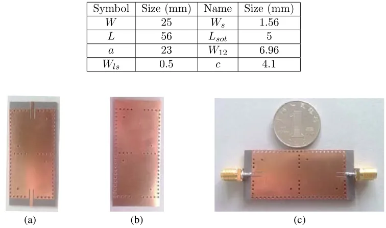
Table 2. Dimensions of the filter.
Symbol Size (mm) Name Size (mm)
W 25 Ws 1.56
L 56 Lsot 5
a 23 W12 6.96
Wls 0.5 c 4.1
(a) (b) (c)
Figure 7. Photographs of the fabricated filter. (a) Top metal layer, (b) bottom metal layer, (c) the filter with SMA.
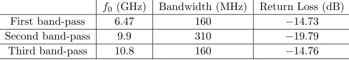
are also observed. From Table 3 it can be seen that the measured in-band return losses are below
6 7 8 9 10 11 12 Frequency (GHz)
-50
Figure 8. Simulated and measured results.
Table 3. The measured results of triple-band SIW filter.
f0 (GHz) Bandwidth (MHz) Return Loss (dB)
First band-pass 6.47 160 −14.73
Second band-pass 9.9 310 −19.79
Third band-pass 10.8 160 −14.76
4. CONCLUSION
A novel triple-mode triple-band SIW filter using two square cavity resonators is proposed in this paper. For achieving triple-mode, TE101 mode and the first degenerate modes are excited by placing two additional vias at the diagonal of a resonator. The resonant frequencies and electric field distributions have then been simulated for a resonator. Finally, a compact planar triple-band filter with three center frequencies at 6.47 GHz, 9.9 GHz and 10.8 GHz (over C-band and X-band) has been designed and fabricated on a 0.508 mm-thickness F4B substrate based on the proposed SIW resonator. By shifting the position of the perturbation vias, the center frequencies of the first and third pass-bands can be adjusted while that of the second pass-band remains unchanged. This character can be used to control the resonant frequency ratio of the three pass-bands within limits. Both simulated and measured results suggest that the proposed SIW resonator is an attractive candidate to design compact planar triple-mode filters. The proposed design method and structure can be easily achieved in similar filters using LTCC to improve the operation bandwidth of filter and even better frequency response selectivity. Since the coupling matrix is frequency independent, the proposed filter suffers from a very narrow frequency band. To improve this limitation, frequency-dependent coupling technique should be taken into account, which will be presented in our future work.
ACKNOWLEDGMENT
This work is supported by the National High-tech Research Development Plan (863 Plan) (2015AA016201).
REFERENCES
2. Weng, M. H., C. H. Kao, and Y. C. Chang, “A compact dual-band bandpass filter with high band selectivity using cross-coupled asymmetric SIRs for WLANs,” Journal of Electromagnetic Waves and Applications, Vol. 24, Nos. 2–3, 161–168, 2010.
3. Hu, J. P., G. H. Li, H. P. Hu, et al., “A new wideband triple-band filter using SIR,” Journal of Electromagnetic Waves and Applications, Vol. 25, No. 16, 2287–2295, 2011.
4. Chen, Z.-X., D. Li, and C.-H. Liang, “Novel dual-mode dual-band bandpass filter using double square-loop structure,”Progress In Electromagnetics Research, Vol. 77, 409–416, 2007.
5. Amari, S. and U. Rosenberg, “New in-line dual-and triple-mode cavity filters with nonresonating nodes,”IEEE Transactions on Microwave Theory and Techniques, Vol. 53, No. 4, 1272–1279, 2005. 6. Deslandes, D. and K. Wu, “Integrated microstrip and rectangular waveguide in planar form,”IEEE
Microwave and Wireless Components Letters, Vol. 11, No. 2, 68–70, 2001.
7. Zhang, L., W. Hong, K. Wu, et al., “Novel substrate integrated waveguide cavity filter with defected ground structure,”IEEE Transactions on Microwave Theory and Techniques, Vol. 53, No. 4, 1280– 1287, 2005.
8. Deslandes, D. and K. Wu, “Substrate integrated waveguide dual-mode filters for broadband wireless systems,”Proceedings IEEE Radio and Wireless Conference, 2003, RAWCON’03, 385–388, 2003. 9. Huang, T. H., C. S. Chang, H. J. Chen, et al., “Simple method for a K-band SIW filter with
dual-mode quasi-elliptic function response,” Microwave and Optical Technology Letters, Vol. 49, No. 6, 1246–1249, 2007.
10. Shigeki, F., “Waveguide line,” Japan Patent, 06-053, 1994.
11. Uchimura, H., T. Takenoshita, and M. Fujii, “Development of a ‘laminated waveguide’,” IEEE Transactions on Microwave Theory and Techniques, Vol. 46, No. 12, 2438–2443, 1998.
12. Chang, C. Y. and W. C. Hsu, “Novel planar, square-shaped, dielectric-waveguide, single-, and dual-mode filters,” IEEE Transactions on Microwave Theory and Techniques, Vol. 50, No. 11, 2527–2536, 2002.
13. Shen, W., X. W. Sun, W. Y. Yin, et al., “A novel single-cavity dual mode substrate integrated waveguide filter with non-resonating node,” IEEE Microwave and Wireless Components Letters, Vol. 19, No. 6, 368–370, 2009.
14. Dong, Y., W. Hong, H. Tang, et al., “Millimeter-wave dual-mode filter using circular high-order mode cavities,” Microwave and Optical Technology Letters, Vol. 51, No. 7, 1743–1745, 2009. 15. Li, R. Q., X. H. Tang, and F. Xiao, “Substrate integrated waveguide dual-mode filter using slot