An Efficient Vertical Seismic Response of a Precast
Segmental Bridge Superstructure: A Study
Bhukya Ramu
ABSTRACT:This paper investigates numerically theverticalnon-linear dynamic reaction of an easy span segmental bridge superstructure that consists of ABC layoutstandards. The superstructure segments are confused collectively via continuous internal unbonded tendons to make certainthe system’s more desirable self-centering capability. A collection of Incremental Dynamic Analysis (IDA) is carried out with the aid ofscaling a set of vertical historic earthquake floor motions to distinctive intensity ranges. The response of thesegmental superstructure bridge device is evaluated via assessing the variability of feature responseportions and assigning performance limit states.
KEYWORDS-unbonded tendons; incremental
dynamic analysis; non-linear dynamic response; limit states
I. INTRODUCTION
Steel bridges are commonly considered to perform nicely in earthquakes, and the implication is regularly made that they have to beused extra regularly in seismically active areas. It seems thatthis argument is based totally on the truth that few if any, steel
bridgeshave collapsed in North American
earthquakes, in comparison to theoverall performance of structural concrete bridges.If a metal bridge is described as one with a metal superstructureand a metal substructure, there are only a few of these in westernNorth America, or even fewer had been subjected to strongfloor motions within the remaining decade or so. However, if a steel bridgeincludes those with concrete substructures ~piers, and columns!The populace will increase significantly, but continues to be a long way less than thatof structural concrete bridges ~in western North America!. Evenso, overall performance facts for those bridges are tough to locate, and especially for bridges subjected to sturdy shaking.
Nevertheless, it is able to be inferred that metallic bridge superstructures are liable to damage even for the duration of low-to-moderateshaking, and appear
to be greater fragile than structural
concretesuperstructures in this regard if not designed well. Typicalharm consists of unseated girders and screw-ups in connections,bearings, pass-frames, and growth joints. In some instances ~appreciably in the course of the Kobe earthquake! Predominant gravity load-sportingparticipants have failed, brought on in a few times by way of the failure ofadditives somewhere else inside the superstructure ~a bearing, as an example!.It may also, therefore, be argued that the recognition loved by using steelbridges is because of the reality that very few steel bridges weresubjected to robust floor movement, and the absence of disintegratingmay be due to a lack of exposure as opposed to the inherent potentialof metallic bridges. Supporting this view is the statement that harm at some stage in low-to-moderate shaking shows a degree of fragility inmetal bridges not visible in structural concrete superstructures.
It is crucial to word on this argument that seismic layoutspecs for bridges within the United States do no longer require thespecific design of bridge superstructures ~concrete or metallic! Forearthquake masses. The assumption is made that a superstructurethat is designed for out-of-aircraft gravity hundreds has enoughstrength, by default, to withstand in-plane earthquake loads. This assumption appears to be justified for structural concrete superstructures, that are heavier and stiffer than their steel opposite numbers but can be unfounded for positive styles of steel superstructures,including trusses or slab-and-girder superstructures, both of whichmay be flexible in-aircraft.
the weight routeas well as the capacities of person components and assembledsystems. Applications of modern technologies, which includes ductileend cross frames ~or diaphragms! And other embedded energydissipators, deserve further take a look at.
II. RELATED WORKS
The prototype bridge structure used for this study is the one considered by Megally et al. (2002). It is asingle-cell box girder bridge that consists of five spans with three interior spans of 30.5 m (100 ft) andexterior spans of 22.9 m (75 ft) for a total length of 137.2 m (450 ft). Each span of the prototypestructure is post-tensioned with a harped-shape tendon. The segmental superstructure modelconsidered in this study represents the centre span of the prototype bridge with two overhangs. Theinterior span length is 30.5 m (100 ft) and the length of each overhang is 7.6 m (25 ft) for a total lengthof 45.7 m (150 ft).
In order to comply with the ABC techniques for precast segmental bridges, the superstructure isdivided into segments. A segment-to-segment joint is provided at the mid-span section, where highbending moments and low shear forces are induced. Mid-span is also the location where maximumrelative displacement of the segments is expected when the superstructure is subjected to verticalseismic loading. The segmental superstructure consists of six interior segments 6.1 m (20 ft) long andtwo exterior segments 4.6 m (15 ft) long. The precast segments are match cast, which means that eachsegment is cast against the previous one so that the end face of one segment is an imprint of theneighbour segment. No shear keys or epoxy adhesives are considered at the joints. The uniformbehaviour of the system is achieved through post-tensioning of the segments with internal unbounded tendons (DYWIDAG, 2009)
III. MODELLING APPROACH
A two-dimensional numerical model of the segmental
superstructure, which incorporates material
andgeometric nonlinearities, is developed and
analyzed using the inelastic dynamic analysis softwareRUAUMOKO (Carr, 2007). The segments of the superstructure are modeled using linear elasticbody kind contributors besides for a vicinity at the ends of every segment that's discretized into severalaxial non-linear springs. The springs are connected to the ends of the superstructure beam factorsthru inflexible body links.Prior to loading, a joint between two adjacent segments is closed and the complete section is incompression. When a vertical seismic load is applied, the joint opens and a compressive contact sectorpaperwork. In order to correctly simulate the contact region among adjoining segments, the wide variety anddistribution of touch springs will be decided on such that the area and 2d second of inertia of thecontact springs do now not significantly deviate from the place and 2d moment of inertia of thesuperstructure’s go-segment. The hysteresis rule used to version the touch springs is the bi-linearwith slackness hysteresis rule (Carr, 2007). A huge initial slackness displacement cost is chosen tomake certain that no tensile forces are evolved within the springs.
Based on the geometry of the superstructure’s
go-section, the touch quarter between two
adjoiningsegments is modeled with 11 nonlinear touch springs, eight of that are located on the pinnacle andbottom plate where most neighborhood deformations are expected. In order to compute the axial stiffnessof the touch springs, their length will be predicted primarily based on the geometric traits of thesuperstructure’s pass-segment. For this look at, the portion of the superstructure’s segments modeled by usingcontact springs is assumed to be same to h/eight, in which his the intensity of the move-phase, consequently 23.0 cm(9.0 in) at every end.
modelling approach can be found inAnagnostopoulou (2009).
Figure 2.1 shows the geometry of the developed
segmental superstructure and the
correspondingnumerical model. The location of the segment-to-segment joints is indicated together with the variousstructural elements (e.g., concrete segments/frame members, joints/contact spring elements,tendons/spring elements). By performing a modal analysis of the numerical model, the first naturalperiod of the system is found to be 0.305 sec (3.28 Hz) and the second and third natural periods arefound to be 0.106 sec (9.42 Hz) and 0.007 sec (14.14 Hz), respectively.
Figure 2.1. Geometry of the one-span segmental bridge superstructure and the developed numerical
model
IV. INCREMENTAL DYNAMIC
ANALYSIS
The site location for the bridge model is assumed to be in the Western United States, close to the Cityof Los Angeles. The design spectrum is selected from the AASHTO LRFD Bridge DesignSpecifications (2007) and represents a seismic event with a 10% probability of exceedance in 50 years(475-year return period). The acceleration coefficient, A, is assumed to be equal to 0.60 (Seismic Zone4) and the site coefficient, S, equal to 1.20 (Soil profile type II). Moreover, the Design Earthquake(DE) and Maximum Considered Earthquake (MCE) response spectra are defined according toASCE/SEI 7-05 (2005). For the specific site location and 5% of critical damping, ASCE specifies thefollowing design and maximum earthquake spectral response
acceleration parameters: SDS equals1.415 g, SD1 equals 0.784 g, SMS equals 2.123 g and SM1 equals 1.176 g.The segmental superstructure model is analyzed using the far-field earthquake ground motionensemble defined in FEMA P-695 (2009). The
ensemble consists of twenty-two historical
strongground motions. Initially, a scaling procedure is applied to the horizontal components of the P-695
ground motions: for the DE and MCE intensity levels, the acceleration response spectrum of eachrecord (2×22 = 44 records) is multiplied by a factor defined as the ratio of the DE and MCE spectralaccelerations, respectively, at a target period equal to the fundamental period of vibration of thesuperstructure model, over the geometric mean of the forty four horizontal spectral acceleration valuesat the same target period. Given that the current bridge design codes provide little guidance on thedevelopment of vertical design spectra, the scale
factors obtained from scaling the
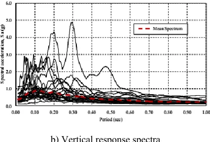
horizontalcomponents of the ground motions are also used for scaling the vertical components of the groundmotions to the DE and MCE intensity levels (the vertical component of one record is not available, so21 records are considered in total). Figure 3.1 shows the results of the scaling method for thehorizontal and vertical components of the P-695 ground motions at the DE intensity level.
b) Vertical response spectra
Figure 3.1. Horizontal and vertical Design acceleration response spectra
IV. PERFORMANCE LIMIT STATES
The overall performance limit states of the segmental superstructure can be defined whilst the numerical versionis analyzed below a vertical cyclic sinusoidal displacement-managed load, which fits the profileof the version’s first mode of vibration. Four overall performance restrict states are identified: the onset of jointcommencing; the cracking of the phase; the onset of spalling of the segment’s excessive concrete fibbers;and either the crushing of the segment’s constrained core or the yielding of the tendons.The first overall performance restriction nation, specified via PS1, is related to the onset of joint commencing.According to AASHTO (2007), a segmental superstructure should behave as a monolithic gadget for theserviceability restrict states and allow for joint opening underneath the closing limit states. The allowablecompressive concrete pressure for pre-burdened additives with unbonded tendons at carrier restrict kingdomis same to 0.60f’c while; no tensile stresses shall develop. Considering a concrete compressiveelectricity, FC’, equal to 34.5MPa (5.0 ksi), the allowable compressive stress is 20.7 MPa (three.Zeroksi) andthe corresponding concrete stain, εc, is 0.07%. In terms of maximum vertical displacement, theAASHTO (2007) specifies a deflection restrict identical to L/800 under the effect of vehicular masses, whereL is the span duration of the bridge. For the case of the segmental superstructure version with an indoorsspan period
same to 30.5 m (one hundred ft), the deflection restriction is about equal to three.8 cm (1.5 in).The 2nd overall performance restriction kingdom, unique by means of PS2, is associated with the initiation of cracking inthe ends of each section and adjoining to the phase-to-phase joints. The pressure degree at whichcracking of the unconfined concrete occurs is believed to be identical to 0.12% (AASHTO, 2007). The thirdperformance restrict country, detailed by means of PS3, is related to the onset of spalling of the extremeconcrete fibbers adjacent to the phase-to-segment joints. The pressure stage at which the coverconcrete ceases to hold any stresses is assumed to be same to 0.30% (AASHTO, 2007).
The fourth overall performance restriction state, specified via PS4, is associated either with the crushing of therestricted concrete middle or the yielding of the tendons. The strain level at which crashing of thelimited concrete takes place is thought to be same to at least 1.0%.
V. CONCLUSION
This paper offers the outcomes of a numerical study that investigates the response of a phaseconcrete bridge superstructure while subjected to vertical earthquake motions. The recommendeddevicewhich makes use of inner unbonded tendons as the handiest continuous reinforcement along the bridge’s lengthis designed to show off high ductility and more desirable self-centering competencies. The number one device used inthis research is a numerical version, which includes material and geometric nonlinearities, andis analysed below a fixed of multi-data Incremental Dynamic Analysis (IDA).
REFERENCES
AASHTO (2007). AASHTO LRFD Bridge Design Specifications, Americn Association off state Highway andTransportation Officials, Washington, D.C., United States.
Anagnostopoulou, M. (2009). Seismic Design and
Analysis of Precast Segmental Concrete
BridgeSuperstructure, Master Dissertation, Centre for
EarthquakeEngineering and Engineering Seismology (ROSE School), University of Pavia, Italy.
ASCE/SEI (2005). Minimum Design Loads for Buildings and Other Structures, ASCE/SEI 7-05, AmericanSociety of Civil Engineers, United States.
Carr, A.J. (2007). RUAUMOKO – Inelastic Dynamic Analysis, Department of Civil Engineering, University ofCantebury, Christchurch, New Zealand.
DYWIDAG-SYSTEMS INTERNATIONAL (2009).
DYWIDAG Mono-strand Post-Tensioning
System,DYWIDAG-Systems International, Illinois, United States.
FEMA (2009). Quantification of Building Seismic Performance Factors, FEMA P-695, Applied TechnologyCouncil for the Federal Emergency Management Agency, Washington, D.C., United States.
Megally, S.H., Garg, M., Seible, F., Dowell, R.K. (2002). Seismic Performance of Precast Segmental BridgeSuperstructures, Structural Systems Research Project SSRP 2001/24, University of California at San Diego,La Jolla, California, United States.
Ou, Y. C., Tsai, M. S., Chang, K. C., Lee, G. C. (2010). Cyclic behavior of precast segmental concrete bridgecolumns with high performance or conventional steel reinforcing bars as energy dissipation bars.
Earthquake Engineering and Structural Dynamics. 39:11, 1181-1198.Vamvatsikos, D. and Cornell, C.A. (2002). Incremental dynamic analysis. Earthquake Engineering andStructural Dynamics. 31, 491-514.
BIODATA
Bhukya Ramu Completed B.E-Civil Engg. from