R E S E A R C H
Open Access
Research on fine boring simulation based
on squeezed liquid film damper
Qiang Shao
1,3, Dong Wang
2, Ping-shu Ge
1,3and Le Wang
2*Abstract
The liquid film damping is one of the main technology for the aerospace, navigation, and machine tool. However, the research on the fine boring is very limited. The paper set up the fine boring squeezed liquid film damped system of multi degree of freedom vibration simulation model and solve mathematical model by transfer matrix theory. The damping coefficient for the fine boring system can be obtained. The mechanical device of liquid film damping system is established. 20# machine oil, 40# machine oil, and cutting fluid are used to the system. The tests indicate that the effect of liquid film formed by cutting fluid is better than oil film formed by machine oil in the static test, but oil film formed by machine oil is better than liquid film formed by cutting fluid in the effect of dynamic test. The simulation model has high accuracy to reliability. The simulation model can directly obtain the optimal parameters, so as to provide effective way to guide field processing.
Keywords:Fine boring, Squeezed liquid film, Damp, System simulation
1 Introduction
At present, the liquid film damping technology has widely research and application in the areas such as aerospace and machine tool [1–4]. But the liquid film (including oil film) damping technique is applied to fine boring processing at home and abroad for the first time. And the fine boring li-quid film damping system can be carried on through the theoretical analysis and experimental research. A reason-able mathematical model for simulation is established on the basis of the direct analysis on the influence on many pa-rameters of the system [5–8]. So the parameter optimization and the excellent fine boring liquid film damping of shock absorber are designed.
Fine boring liquid film damping system has a simple structure. The inside and outside of the damper is filled with liquid. Under the condition of high-speed rotation, a squeezed liquid film is formed between the workpiece and damping sleeve because of the boring bar’s lateral vibration. At the same time, the damping force is pro-duced for preventing the gap between the workpiece and the damping. So it can consume vibration energy of the boring bar, reduce the amplitude, and improve the ma-chining quality of fine boring.
2 Methodology
Over the years, many experts and scholars at home and abroad devoted themselves to the boring bar dynamics analysis. But most of them were based on a single degree of freedom vibration system. The influence of the main modes on more degree of freedom system is ignored be-cause of single degree of freedom system in the vibration of the system. So the analyses of the system are not ac-curate enough. In this paper, the author will consider the fine boring squeeze liquid film damping system as a multiple degree of freedom vibration system [9–11], and it can significantly improve the accuracy of the vibration analysis. Its dynamic model has lots of types, including: ① lumped parameter model, ② distributed parameter model, and ③ hybrid parameter model. To analyze the vibration characteristics of boring bar concrete parts, the paper use the lumped parameter model. This tool loca-tion can be regarded as inelastic quality unit for vibra-tion characteristic analysis [12]. The law of the system vibration is concluded more accurately.
Each part of the boring bar length and the diameter num-ber is as follows:L1= 40 mm, D1= 56 mm; L2= 100 mm, D2= 40 mm;L3= 100 mm,D3= 40 mm; and L4= 40 mm, D4= 36 mm. Damper and liquid film clearance of work-piece respectively are 0.05, 0.10, 0.15, and 0.10 mm, damper liquid using emulsion 20# machine oil.
* Correspondence:[email protected]
2College of Engineering Education, Dalian Minzu University, Dalian 116600, China
Full list of author information is available at the end of the article
The equipment starts and begins to process. The eddy current sensor can be used to detect the vibration of the boring bar. The detected vibration signals are input to the computer through the amplifying circuit and the AD converter to carry out the data collection and storage.
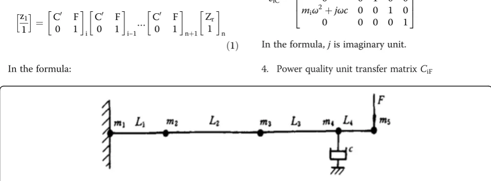
The whole system is divided into a series of quality unit and elastic rod unit with no quality. The damping unit and power unit with quality units is combined into a special quality unit. So the whole system is composed of quality unit, elastic shaft unit, damp-quality unit, and power-quality unit. The number of the specific units is decided by the required precision. The more the number of units is, the higher the accuracy of the model analysis is (take nine units in this paper).
The lumped parameter system dynamic model is shown in Fig.1.
In Fig.1,“F”for exciting force, these five quality units are calculated according to the length, diameter, and density of the boring bar, respectively as follows: m1= 0.385 kg, m2= 0.875 kg, m3= 0.98 kg, m4= 0.685 kg, and m5= 0.195 kg.
After the system dynamics model is set up, according to transfer matrix theory, the system mathematical model is established and to solve mathematical model, so as to lay foundation for the establishment of the sys-tem simulation model. It is known from the transfer matrix theory that the left and right side system units have a state vector to represent the unit state, denoted as Zl (left side) and Zr (right side); the relationship be-tween the state vector can be represented as:
Z1¼CZr
Cis a unit transfer matrix or a transfer matrix, and it can be introduced from this: The transfer matrix be-tween any two unit state vectors is multiplied to all unit transfer matrices of the two state vectors. The following is expressed as follows:
z1
C′is the first four-order square matrices of each trans-fer matrix.
According to the force balance relations, every each unit can obtain the following transfer matrix.
1. Inelastic quality unit transfer matrixCim
cim¼
In the formula,ωis circular frequency.
2. Inelastic mass element transfer matrixCiL
ciL¼
In the formula, EI is moment of inertia.
3. Damp-quality unit transfer matrixCiF
ciC¼
In the formula,jis imaginary unit.
4. Power quality unit transfer matrixCiF
ciC¼
Both sides of system state vector of transfer matrix equations can be concluded by plugging formula4 into formula1.
All the matrices in the formula are both five-order square. Y, θ, M, and F respectively represent the dis-placement, angle, torque, and force. The left side vector represents left side state vector of the system, and the right side vector represents right side state vector of the system. So the product of the matrix is still 5 square, the Cgis as follows:
Because the boring bar is closely connected with ma-chine tool axle shaft of Morse taper hole, the system can be as a cantilever beam fixed at one end. So the system boundary conditions are as follows:
Y11¼0 θ11¼0 M5r¼0 F5r¼ F
The equation can be gotten:
0¼C11Y5þC12θ5þC14P
0¼C21Y5þC22θ5þC24P
The root of the equation:
Y5¼
C12C24−C22C14
C11C22−C12C21
F ð3Þ
As a result of the existence of system with damping device,Y5is plural
Y5¼ζrþjζi¼AcosðωtþφÞ ð4Þ
Through the above model, we know that the system response to external simple harmonic excitation is still the harmonic vibration, the amplitude of response is a function of damping coefficient c and excitation fre-quencyω, where it can be expressed as:
A¼ F Cð ;ωÞ ð5Þ
The resonance amplitude is:
Amax¼ maxF cð ;ωÞ ð6Þ
3 Results and discussion
3.1 Reliability analysis of the simulation model
Static test was done under the condition of the machine not working, and vibration adopts the method of exter-nal excitation. Its purpose was to test the vibration of the boring bar in the two cases: with damper or not. In the static test, study is done to get the relationship of the damper’s parameters and vibration damping effect. The CA6140 lathe was modified to carry boring machin-ing with the bormachin-ing bar installed in the lathe spindle Morse taper hole [13]. The workpiece was clamped by the fixture and installed on the sliding board. Emulsion and the 20# machine oil were used as damping liquid re-spectively. The test data signals was obtained through acceleration sensors, which was sent to a computer to process after signal amplification and A/D conversion. Table 1 is the results with different damping sleeve width and damping fluid (oil) film thickness in the cases with fluid (oil) film and no fluid (oil) film. Trial dampers’ inside diameter isD= 60 mm, the absolute liquid viscos-ity coefficientη= 5.949 Pa∙s. The results of the data test are shown in the following Table1:
An empirical formula for damping coefficient can be got by the relevant parameters of the dampers. It repre-sents the law of the liquid film under the finite long axis in the table.
c¼ ηLR3
δ3a 1ð −εÞb ð7Þ
In the equation,R=D/2.
a and b are constants associated with damper parameters.
a¼0:6ðD=LÞ−0:4;b¼l:5þ0:3pffiffiffiffiffiffiffiffiffiD=L
δis the damping sleeve and the processing hole clear-ance value, the thickness of liquid film
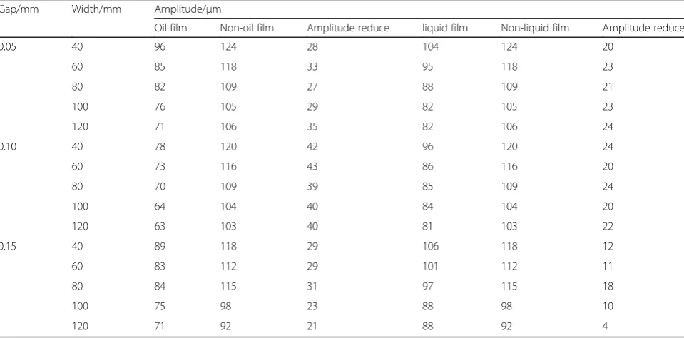
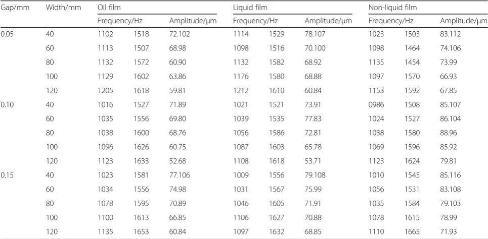
Under the single damping and complex damping, the static test with liquid film and non-liquid film is carried out. Some important data can be measured as shown in Tables2,3, and4.
From Tables2,3, and4, it can be seen that squeeze li-quid (oil) film damper can inhibit the vibration of boring bar no matter in the static excitation or dynamic cutting. In the static test, the effect of liquid film formed by cutting fluid is better than oil film formed by machine oil. In the effect of dynamic test of oil film formed by machine oil is better than liquid film formed by cutting fluid.
From Table 4, it can be seen from all the test data, with the increase of damping sleeve width, the boring bar vibration amplitude was decreased gradually, but when the damping sleeve width continue to increase, the amplitude had a tendency of increase. The change rule can be explained as follows.
From Tables2,3, 4, and5, the test curve of amplitude and resonance frequency with the damping value of num-ber can drew. The curve line is shown in Figs.3and4.
In addition, the curve of the amplitude and the reson-ant frequency from Eqs. (5), (6) paint and the damping value simulation curve can be shown in Figs. 2 and 3. To be sure, in the simulation study, the size of the force F only affects the position of the curve along the longi-tudinal axis, does not affect the shape of the curve and the changing trends, and so does not affect the essence of the problem. it can be understand of formula (3). In this case, takeF= l.028 KN.
In the Figs. 2 and 3: Both amplitude damping curve and resonance frequency damping curve are very close, and it indicates that the simulation results are basically in agreement with the experimental results; it can be seen that establishing the simulation model is reasonable and reliable.
3.2 Parameter optimization of damper
In the design of damper, the main parameters affect the effects of vibration reduction for the thickness δ (mm) and the length L (mm) of the liquid film damper. In
Table 2Single damping oil film, liquid membrane effects on spindle amplitude
Gap/mm Width/mm Amplitude/μm
Oil film Non-oil film Amplitude reduce liquid film Non-liquid film Amplitude reduce
0.05 40 96 124 28 104 124 20
60 85 118 33 95 118 23
80 82 109 27 88 109 21
100 76 105 29 82 105 23
120 71 106 35 82 106 24
0.10 40 78 120 42 96 120 24
60 73 116 43 86 116 20
80 70 109 39 85 109 24
100 64 104 40 84 104 20
120 63 103 40 81 103 22
0.15 40 89 118 29 106 118 12
60 83 112 29 101 112 11
80 84 115 31 97 115 18
100 75 98 23 88 98 10
120 71 92 21 88 92 4
Table 1Field test raw data
Separation
δ/μm
Frequency f/Hz amplitude A/μm
The length of the damper L/mm 50
The length of the damper L/mm 60
The length of the damper L/mm 80
The length of the damper L/mm 100
The length of the damper L/mm 120
75 1177/2.6 1429/2.9 1355/2.0 1577/1.6 1335/2.2
100 1337/2.6 1440/2.8 1598/3.5 1524/3.3 1724/4.5
150 1459/1.4 1434/1.9 1492/1.1 1609/4.9 1660/2.7
order to determine the optimal parameters, more groups of dynamic test have been done under the conditions of the actual processing conditions. Because cost is high, the large amount of test is hard to proceed. The law of various parameters on the vibration reduction is ana-lyzed by the simulation model. The results can directly get the optimal parameters, so as to effectively guide field processing.
The δ value is ensured in a certain range, and the other parameters are constant. Using formula (7) into
formula (5), the relation curve of liquid film thickness– amplitude is drew and shown in Fig.4. In the same way, the liquid film length-amplitude relation curve are drew and shown in Fig.5.
As seen in Figs.4and5, the optimal thickness of the δ and the lengthL of the liquid film damper is 0.l and 60 mm respectively. According to the data, the author designed the damping shock absorber, and it has been applied in Dalian Locomotive Plant a TX611C type digital display horizontal boring machine. As the result,
Table 3Single damping oil film, liquid membrane effect on main frequency
Gap mm
Width mm
Frequency/Hz
oil film Non-oil film Amplitude reduce liquid film Non-liquid film Amplitude reduce
0.05 40 1419 1403 16 1392 1403 11
60 1438 1424 14 1445 1424 21
80 1466 1424 42 1450 1424 26
100 1516 1456 60 1482 1456 26
120 1566 1492 74 1542 1492 50
0.10 40 1425 1389 36 1419 1389 30
60 1450 1403 47 1447 1403 44
80 1534 1467 67 1507 1467 40
100 1521 1426 96 1536 1476 40
120 1607 1518 89 1605 1518 87
0.15 40 1432 1409 23 1411 1409 2
60 1414 1392 22 1416 1392 24
80 1455 1444 11 1444 1432 12
100 1472 1453 19 1440 1453 7
120 1574 1524 50 1553 1524 29
Table 4Double damping oil film, liquid membrane for the main shaft frequency and amplitude
Gap/mm Width/mm Oil film Liquid film Non-liquid film
Frequency/Hz Amplitude/μm Frequency/Hz Amplitude/μm Frequency/Hz Amplitude/μm
0.05 40 1102 1518 72.102 1114 1529 78.107 1023 1503 83.112
60 1113 1507 68.98 1098 1516 70.100 1098 1464 74.106
80 1132 1572 60.90 1132 1582 68.92 1135 1454 73.99
100 1129 1602 63.86 1176 1580 68.88 1097 1570 66.93
120 1205 1618 59.81 1212 1610 60.84 1153 1592 67.85
0.10 40 1016 1527 71.89 1021 1521 73.91 0986 1508 85.107
60 1035 1556 69.80 1039 1535 77.83 1024 1527 86.104
80 1038 1600 68.76 1056 1586 72.81 1038 1580 88.96
100 1096 1626 60.75 1087 1603 65.78 1069 1596 85.92
120 1123 1633 52.68 1108 1618 53.71 1123 1624 79.81
0.15 40 1023 1581 77.106 1009 1556 79.108 1010 1545 85.116
60 1034 1556 74.98 1031 1567 75.99 1056 1531 83.108
80 1078 1595 70.89 1046 1605 71.91 1035 1584 79.103
100 1100 1613 66.85 1106 1627 70.88 1078 1615 78.99
the surface roughness has improved to a better vibra-tion damping effect than in the past (seen Fig.6).
3.3 Experiment results and discussion
The tests indicate that no matter what static and under the cutting condition, liquid membrane (includ-ing oil film) for bor(includ-ing bar has good vibration
damping effect, the best damping effect at more than 20%. A lot of experimental data show that, when the liquid film thickness and width are 0.1 and 60 mm, re-spectively, damping effect is best. In simulation, the simulation curve is in agreement with the experimen-tal curve, and it shows the simulation is good and suited for some testing.
The experiment is divided into static and dynamic ex-periments. In the static experiments, liquid film damper is better than the oil film damper damping effect. In dy-namic cutting experiments, the oil film damping effect is better than the liquid film damping effect in general.
Table 5Cutting, liquid film, and oil film influence on the spindle amplitude
Gap/mm Width/mm Frequency/Hz
Oil film Liquid film No film
0.05 40 52 56 60
60 49 54 59
80 42 44 52
100 45 45 52
120 51 46 53
0.10 40 50 54 62
60 47 52 60
80 44 45 55
100 41 46 50
120 40 47 51
0.15 40 53 58 61
60 50 54 55
80 43 50 53
100 43 49 52
120 44 48 51
Fig. 2Response amplitude and damping
value diagram
Fig. 3Resonance frequency and the damping
value diagram
Fig. 4Liquid film thickness and response amplitude
Fine boring liquid film damping system can greatly im-prove the machine tool dynamic stiffness and cutting vibration resistance, while not reducing other perform-ance indicators. It has a simple structure and reliable performance.
4 Conclusions
This paper presented an experimental study on fine bor-ing squeezed liquid film damped system, and settbor-ing up a freedom vibration simulation model. Some mathemat-ical model can be solved by transfer matrix theory. The mechanical device of a liquid film damping system is established. 20# machine oil, 40# machine oil, and cutting fluid are used to the system. The following con-clusions can be drawn from this study.
1. The damping coefficient for the fine boring system can be obtained.
2. Using multi degree of freedom system vibration simulation model to analyze the squeeze liquid film damping system has high reliability and accuracy. 3. Using the simulation model can reduce the test
cost, direct access to optimize parameters of shock absorber on the basis of parameter design and manufacture of shock absorber, and bring good effect in practice.
Acknowledgements
The research presented in this paper is supported by Dalian Minzu University and State ethnic Affairs Commission of China.
Funding
The authors acknowledge the Fundamental Research Funds for the Central Universities (Grant: DC201502010305), Liaoning Provincial Natural Science Foundation of China (Grant: 201602196).)
Authors’contributions
QShao is the main writer of this paper. He proposed the main idea, deduced the performance of liquid film damper, completed the simulation, and analyzed the result. LWang introduced the liquid film damper for testing. DWang simulated the liquid film damper by soft. P-SGe gave some important suggestions for the liquid film damper. All authors read and approved the final manuscript.
Competing interests
The authors declare that they have no competing interests.
Publisher’s Note
Springer Nature remains neutral with regard to jurisdictional claims in published maps and institutional affiliations.
Author details 1
College of Mechanical and electronic Engineering, Dalian Minzu University, Dalian 116600, China.2College of Engineering Education, Dalian Minzu University, Dalian 116600, China.3Key laboratory of Intelligent Perception and Advanced Control of State Ethnic Affairs Commission, Dalian 116600, China.
Received: 9 March 2018 Accepted: 30 May 2018
References
1. H Sasaki, N Ochiai, Y Iga, Numerical analysis of damping effect of liquid film on material in high speed liquid droplet impingement. Int J Fluid Machine Syst9(1), 57–65 (2016).
2. Y Matsumura, T Shiraishi, S Morishita, Stiffness and damping of liquid crystal lubricating film under electric field. Tribol. Int.54, 32–37 (2012).
3. Shao Qiang, Song Peng, Feng Changjian. Faults diagnosis for vibration signal based on HMM, Sensors & Transducers, 165(2) ,8–15(2013). 4. S Qiang, S Jia-Heng, T Xiao-Mei, Study on application of squeeze film
damper in precision hole grinding. J. Comput. Theor. Nanosci.13, 5867– 5871 (2016).
Fig. 5Liquid film lengths and response amplitude
relation curve
(a)
(b)
5. S Qiang,Fine boring liquid film damping technique experiment research
(Dalian Railway University, Dalian, 2001).
6. Z Yong-cheng, H Hongbiao, Y Changgang, Z Liang, Simulation of liquid-film-damping system in machining of precise borehole. Chin. J. Mechanic. Eng.39(8), 151–154 (2003).
7. Yu tian-biao, Gong Ya-dong, Jiang zao, Wang Wan-shan. Study on application of squeeze film damper in precision hole grinding. Chin. J. Mechanic. Eng., v39,n12, 114–117, 122 (2003).
8. Y-m Li, Xiao-kui, Research on deep hole drilling chatter control based on film damper. Mod. Mach. Tool Auto. Manufact. Techn.4, 57–59 (2014). 9. R-G Xu, Y Leng, Contact stiffness and damping of liquid films in dynamic
atomic force microscope. J. Chem. Phys.144(15), 21–30 (2016). 10. F Antoine, S Matthew, C Hua, H Christopher, H Kai, M Frederic, M Bruno,
Experimental observation of inertia-dominated squeeze film damping in liquid. J. Fluids Eng. Trans. ASME132(12), 156–165 (2010).
11. Zhao, Shiquan, Zhu, Dan-Hui, Qi, Yongxing, Chen, Hualing. Experiment on vibration reducing capacities of pore viscous damping and liquid film damping. Adv. Mater. Res. v430–432, p1822–1825(2012).
12. S Huang, B-T Diana-Andra, T John, Liquid squeeze film damping in microsystems applications. ICNMM2010, 885–886 (2010).