Iterative MIMO Turbo Multiuser Detection
and Equalization for STTrC-Coded Systems
with Unknown Interference
Nenad Veselinovic
Centre for Wireless Communications, University of Oulu, Tutkijantie 2E, P.O. Box 4500, 90014 Oulu, Finland Email:[email protected]
Tad Matsumoto
Centre for Wireless Communications, University of Oulu, Tutkijantie 2E, P.O. Box 4500, 90014 Oulu, Finland Email:[email protected]
Markku Juntti
Centre for Wireless Communications, University of Oulu, Tutkijantie 2E, P.O. Box 4500, 90014 Oulu, Finland Email:[email protected]
Received 30 November 2003; Revised 16 April 2004
Iterative multiuser detection in a single-carrier broadband multiple-input multiple-output (MIMO) system is studied in this paper. A minimum mean squared error (MMSE) low-complexity multiuser receiver is derived for space-division multiple-access (SDMA) space-time trellis-coded (STTrC) systems in frequency-selective fading channels. The receiver uses MMSE filtering to jointly detect several transmit antennas of the user of interest, while the interference from the undetected transmit antennas, cochannel interference (CCI), and intersymbol interference (ISI) are all cancelled by the soft cancellation. The performances of two extreme receiver cases are evaluated. In the first case, only one transmit antenna of the user of interest is detected at a time and the remaining ones are cancelled by soft cancellation. In the second case, all the transmit antennas are detected jointly. The comparison of the two cases shows improvement with the latter one, both in single-user and multiuser communications and in the presence of unknown cochannel interference (UCCI). It is further shown that in the multiuser case, the proposed receivers approach the corresponding single-user bounds. The number of receive antenna elements required to achieve single-user bound is thereby equal to the number of users and not to the total number of transmit antennas.
Keywords and phrases:turbo equalization, multiuser detection, space-time codes, cochannel interference.
1. INTRODUCTION
The scarcity of the frequency spectrum resources and the ever-growing demand for new broadband services imposes a need for the bandwidth-efficient transceiver schemes. Sig-nal transmission and reception using multiple-transmit and receive antennas over a input multiple-output (MIMO) channel is one of the most promising ap-proaches for increasing the link capacity and the achievable data rates [1]. Two key approaches have been developed to make effective use of the benefits of the MIMO channels. The first one is the Bell-Labs-layered-space-time architec-ture (BLAST) [2], where independent signals are transmit-ted from different transmit antennas. Another technique that combines the benefits of transmit diversity and channel cod-ing in an efficient manner is space-time codcod-ing either in a
form of space-time block coding (STBC) [3] or space-time trellis coding (STTrC) [4]. This paper focuses on STTrC-coded systems.
to perform signal processing for a set of frequency flat-fading channels. The other approach is a combination of equaliza-tion and decoding for single-carrier communicaequaliza-tions. The optimal receiver for the frequency-selective channels is the maximum a posteriori(MAP) equalizer usually implemented by means of the BCJR algorithm [8]. Its complexity, however, grows exponentially with the number of multipath compo-nents. Moreover, in the channel-coded systems, the optimal receiver is the one that performs joint equalization and de-coding and its complexity is exponential in the product of the number of multipath components and the code mem-ory length. Therefore, it is impractical in broadband systems, and low complexity schemes are of a particular interest. The problem of complexity of the optimal joint equalization and decoding can be effectively solved by iterative (turbo) equal-ization principle that was introduced in [9]. Further com-plexity reductions have been mainly based on simplifica-tions of the equalization part. This paper focuses on the low-complexity turbo equalization for single-carrier communi-cations using STTrC codes.
Joint iterative equalization and decoding of STTrC codes is introduced in [10], where the optimal MAP equalizer is used. Its low-complexity extension is proposed in [11], where channel shortening takes place first, and the reduced complexity MAP algorithm is performed afterwards. The technique results in relatively low-performance degradation when compared to the optimal receiver. In the case of de-cision feedback equalization (DFE) combined with STTrC-decoder in an iterative manner, a method for complexity reduction was studied by [12, 13]. This method is based on the decoupling between the real and imaginary parts of the received signal, resulting in a reduced total num-ber of equalizer states. An equalizer based on soft interfer-ence cancellation and MMSE filtering was proposed in [14] for a convolutionally coded system with diversity signal re-ception. The receiver can be seen as an extension of the idea introduced for code-division multiple-access (CDMA) in [15]. It was further extended to cover higher-order mod-ulations in [16, 17], where further complexity reduction methods were proposed as well. In [18], the idea was ap-plied to the multiuser diversity signal detection with con-volutional codes. The reduced complexity version of the receiver, based on matched filter approximation, was pro-posed in [19]. An STTrC coded multiuser system in fre-quency flat MIMO channels was considered in [20]. It em-ploys iterative multiuser detection schemes similar to those of [15,18].
In some situations, the unknown cochannel interference (UCCI) can be present in the channel apart from the users that are to be detected. Those users can originate from the undetected users in the same cell, from the other-cell in-terference, or from other communication systems. In [21], an iterative UCCI suppression method has been studied, which is based on the covariance-matrix-estimation tech-nique. Subspace estimation methods for the UCCI suppres-sion were considered in [20,22] in CDMA and SDMA sys-tems, respectively. A noniterative receiver for detection of STTrC codes in the presence of UCCI was introduced in
[23] in frequency-flat-fading channels. The method of [23] is based on joint detection of all the transmit antennas’ signals using MMSE receiver presented in [24]. A similar solution was proposed in [25] for the orthogonal transmission using STBC codes in flat-fading channels. In [23,25], however, the MMSE filters are different so that the outputs of the latter one are the combined signals from all the receive antennas, while the outputs of the former are the separated outputs for each receive antenna.
In this paper, new low-complexity turbo equalization schemes for the multiuser MIMO-STTrC-coded system are derived. The first part of the studied receivers is soft cancel-lation of both ISI and cochannel interference (CCI). The sec-ond part is a linear MMSE filtering that is used to cope with the residual interference after soft cancellation and UCCI if the latter is present. The degrees-of-freedom (DoF) of the MMSE receiver are thereby decreased depending on the sig-nificance of the residual interference and UCCI. The receiver can be seen as a combination of those considered in [20,25], and their extension to frequency-selective channels. Assum-ing that each transmitter hasNT transmit antennas, the
re-ceiver is derived for the general case of jointly detecting sig-nals in theNT/n0sets containingn0transmit antennas of one
particular user, whereNTis an integer multiple ofn0. The
de-rived receiver’s performance in special cases corresponding ton0=1 andn0 =NT is studied through simulations. The
casen0 =1 can be seen as an extension of the receiver
pro-posed in [20] to the frequency selective channels. The cases of 1 ≤n0 ≤NT are a further receiver extensions where
sev-eral transmit antennas are detected jointly. The aim of joint detection of several transmit antennas’ signals is to preserve the DoFs of the receiver. In case ofn0=NT,NT−1, the DoFs
are preserved.
The UCCI mitigation capability of the proposed receiver is attained by using the iterative covariance estimation tech-nique shown in [21]. It should be noted that the receiver proposed in [20] requires the knowledge of the UCCI chan-nel matrix. Unlike [20], the method of [21] requires only a covariance matrix estimate of the UCCI-plus-noise and it is therefore less complex.
The rest of the paper is organized as follows.Section 2 describes system model.Section 3presents the proposed re-ceiver and its special cases for which either one antenna or all antennas are detected simultaneously.Section 4describes the maximum-likelihood (ML) receiver with perfect feedback, whose performance curve is used as a lower bound on the proposed receivers’ performance.Section 5presents numer-ical results. The paper is concluded inSection 6.
Notation. In the sequel, the following notations were adopted.
(i) (·) denotes the estimate of (·).
(ii) (·)k, (·)(n), and (·)(i) denote dependence of (·) on the
kth user,nth transmit antenna, and timing indexi, re-spectively.
1
Figure1: System model.
(iv) (·)γ denotes the dependence of (·) on theγth
an-tenna set, whereγ=1,. . .,NT/n0.
(v) (·)T, (·)H, and E{(·)} denote transpose, conjugate
transpose, and expectation of (·), respectively. (vi) [(·)]m,n, [(·)]mdenote the (m,n)th element of (·) if (·)
is a matrix and themth element of (·) if (·) is a vector, respectively.
2. SYSTEM AND RECEIVED SIGNAL MODEL
Figures 1 and 2 describe the system model and the kth user’s transmitter block diagram assumed in this paper, re-spectively. Each of K +KI users encodes bit information
sequence ck(i), k = 1,. . .,K + KI, i = 1,. . .,Bk0, using
a rate k0/NT STTrC code, where NT andB are the
num-bers of transmit antennas and frame length in symbols, respectively. The users indexed by k = 1,. . .,K are the users of interest to be detected and the others indexed by k = K + 1,. . .,KI are unknown users. The encoded
se-quences bk(i) ∈ Q, i = 1,. . .,BNT, are first grouped in
Bblocks ofNT symbols, whereQ = {α1,. . .,α2k0}denotes
the modulation alphabet ofM-phase-shift-keying (M-PSK). However, it is straightforward to extend the receiver deriva-tions to quadrature-amplitude-modulation (QAM) schemes. The coded sequence is then interleaved so that the posi-tions within blocks of length NT remain unchanged, but
the positions of the blocks themselves are permuted within a frame according to the user-specific interleaver pattern. Thereby the rank properties of the STTrC codes are preserved [26]. The interleaved sequences are then headed by user-specific training sequences consisting ofTNT symbols. The
entire frame is serial-to-parallel converted, resulting in the sequencesb(n)k (i),n=1,. . .,NT,i=1,. . .,B+T, and
trans-mitted with NT transmit antennas through the
frequency-selective channel.
Figure2: Transmitter block diagram for the first user.
After coherent demodulation in the receiver, the signals from each of NR receive antennas are sampled in time
do-main to capture the multipath components. Observing the signals from different transmit antennas of different users as the virtual users and arranging them in the vector form sim-ilarly as in [18,20], we form the space-time representation of the received signal at time instantigiven by
y(i)=Hu (i)
wherey(i) ∈ CLNR×1 is space-time sampled received signal vector, given by
Lis the number of paths of the frequency-selective channel, andrm(i) denotes the signal sample obtained after matched
filtering at themth receive antenna. Channel matrixH has the form of
user’snth transmit antenna andmth receive antenna. Simi-larly,HIis defined as
1
. . .
NR
Multiuser SC/MMSE detector
. . .
zk1(i) z
N n0
k (i)
logPextSISO(b(1)k (i))
logPextSISO(b(kNT)(i))
logPMMSE(b(1)k (i))
APP ...
logPMMSE(b(kNT)(i))
ForRestimation
. . .
logPSISOAPP(b(1)k (i))
logPAPP SISO(b(kNT)(i))
. . .
S/P Int.
Userk=1,. . .,K
Qext
P/S Deint. STDec
k
S/P Int.
. . .
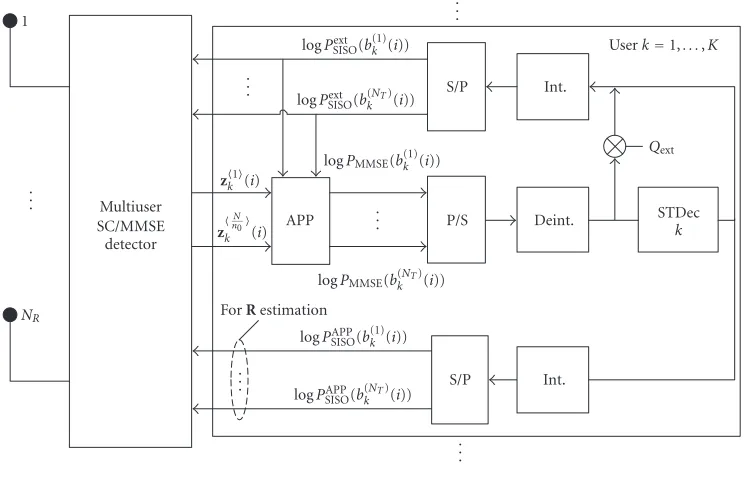
Figure3: Iterative receiver block diagram.
with
HI(l)
=
h(1)K+1,1(l) · · · h(NT )
K+1,1(l)· · · h (1)
K+KI,1(l)· · · h
(NT)
K+KI,1(l) ..
. . .. ... . .. ... . .. ... h(1)K+1,NR(l)· · · h
(NT)
K+1,NR(l)· · · h (1)
K+KI,NR(l)· · ·h
(NT)
K+KI,NR(l)
∈CNR×KINT.
(6)
The vectors u(i) anduI(i) denote the desired and
un-known users’ sequences, respectively, which are defined as
u(i)=bT(i+L−1),. . .,bT(i),. . .,bT(i−L+ 1)T
∈QKNT(2L−1)×1,
uI(i)=
bTI(i+L−1),. . .,bIT(i),. . .,bTI(i−L+ 1)T
∈QKINT(2L−1)×1
(7)
with
b(i)=b(1)1 (i),. . .,b(N1 T)(i),. . .,b(1)K (i),. . .,b(NKT)(i)
T
∈QKNT×1,
bI(i)=
b(1)K+1(i),. . .,b(NT )
K+1(i),. . .,b (1)
K+KI(i),. . .,b
(NT)
K+KI(i)
T
∈QKINT×1.
(8)
Vectorn(i)∈ CLNR×1 contains the spatially and temporally white additive Gaussian noise (AWGN) samples with covari-ance E{n(i)nH(i)} =σ2I.
3. TURBO MIMO EQUALIZERS
The receiver first associates the signals from transmit an-tennas of the kth user to the NT/n0 sets of sizen0, so that
antennas indexed by n = 1,. . .,n0 belong to the first set,
those indexed byn = n0+ 1,. . ., 2n0 belong to the second
set and so forth. Thereby the number of transmit antennas NT is assumed to be an integer multiple ofn0. However, the
receiver derivation for the more general cases of users hav-ing different numbers of transmit antennas and/or different sets of transmit antennas having different sizes is straight-forward. Without loss of generality, the receiver derivation is presented for the first set of transmit antennas of thekth user inSection 3.1. The derivation is exactly the same for the rest of transmit antenna groups and the rest of users, with a dif-ference only in indexing. The SISO channel decoding part and the extrinsic probabilities calculation are presented in Section 3.2. The special cases ofn0 = 1 andn0 = NT are
considered in more detail in Section 3.3. Forn0 = 1, only
one antenna is detected at a time and the receiver can be viewed as an extension of the receiver presented in [20] to the frequency-selective channel. Forn0 =NT, all the
trans-mit antennas are detected jointly, resulting in the preserved DoFs of the receiver.
3.1. SC/MMSE equalizer derivation
Figure 3shows the receiver block diagram. First, an estimate
Hof the channel matrixHis obtained based on the training sequenceu(i),i=1,. . .,T. Then, the covariance matrixRof the UCCI-plus-noise is estimated. In the first iteration, only the training sequence is used for this purpose, resulting in
R= 1
T
T
i=1
Starting from the second iteration, we make use of the soft feedback from the SISO decoding when estimating the co-variance matrix. We denote the soft feedback vector asu(i). Its elements are obtained by replacing the corresponding el-ements ofu(i) by their soft estimates, defined as
b(n)k (i)=
wherePSISOAPP denotesa posterioriinformation obtained after
SISO decoding (to be defined in (27)). The covariance matrix estimate is now obtained by
The estimateRis, therefore, dependent on the iteration in-dex. However, for the simplicity of notation we omit this de-pendence, since the receiver derivation is identical for all it-erations. Moreover, only in the first iteration (9) is used for the estimation of R, while in all subsequent iterations (11) is used. Let the kth user be the user of interest. We further denote
uct and antenna set index, respectively. The vectorsu˜(i) are obtained by replacing the elements ofu(i) by their soft esti-mates, that is, an element is
˜
SISOdenotes the extrinsic information obtained after
SISO decoding (to be defined in (28)). The signalsb(n)k (i),
n=1,. . .,n0, are jointly detected by filtering the signal
yk1(i)=y(i)−Hu k1(i), i=T+ 1,. . .,B+T, (15)
using a linear MMSE filter whose weighting matrixWk1(i) satisfies the following criterion:
Note that (20) holds only for the M-PSK case, although it is straightforward to extend the receiver derivation to the more general signal constellations. Detailed derivation of the optimal solution for a pair of matrices [Wk1(i),Ak1(i)] is given in the Appendix. Assuming that the MMSE filter out-putzk1(i)∈Cn0×1can be viewed as the output of the
equiv-alent Gaussian channel [27], we can write
zk1(i)=Wk1H(i)yk1(i)
equivalent channel, defined as
Ω1
The outputs of the equivalent channelszkγ(i) and their pa-rametersΩkγ(i) andΘkγ(i) forγ=1,. . .,NT/n0are passed
to the APP block that calculates the extrinsic probabilities needed for SISO decoding, as described inSection 3.2.
3.2. APP block and SISO decoding
The SISO channel decoding algorithm used in this paper is a symbol-level MAP algorithm from [28]. For the sake of sim-plicity, we omit the full derivation of the MAP algorithm and we refer to [20,28]. It should be noted that the input required by the decoder is the probabilityP(Si,Si+1) associated with
the transition between two trellis states, Si andSi+1, of the
STTrC code. The transition probability can be calculated as
PSi,Si+1
n ∈Qare the encoder outputs that are associated
with the transition (Si,Si+1).PextMMSE(b(n)k (i)=αq) are
extrin-sic probabilities obtained by the MMSE detection. For the first set of jointly detected signals (n=1,. . .,n0), the
extrin-sic probabilities are calculated in the APP block as
PMMSEext
Based on the transition probabilities P(Si,Si+1), the SISO
channel decoder calculates thea posterioriprobabilities for the symbolsbk(n)(i), defined as
The decoder extrinsic probability is then calculated as
PSISOext
The similar procedure is repeated for all NT/n0 groups of
transmit antennas that are jointly detected, in order to ob-tain all probabilitiesPext
SISO(b(n)k (i) = αq) forn = 1,. . .,NT.
The parameterQext is an ad-hoc parameter that was
intro-duced in [9,20]. It is shown in [20] that if the value ofQext
is appropriately chosen so as to be between 0 and 1, the re-ceiver performance can be significantly improved. This is due to the fact that the extrinsic information in the initial itera-tions is not accurate enough, especially with relatively small
SNR values. By imposing the parameterQext, the effect of this
inaccuracy is reduced, at the expense of slower receiver con-vergence. The result of simulations conducted to evaluate the influence of this parameter on the receiver performance is presented inSection 5.
The receiver complexity is dominated by the MMSE part which requires inversion of the matrixMkγ(i) as well as by the APP block which calculates the extrinsic information of the MMSE detector. The overall complexity is therefore O{max(L3N3
R, 2k0n0)}. It can be seen that the complexity of
the MMSE part does not depend on the number of antennas to be jointly detected. The complexity of the APP part of the receiver, however, increases exponentially withn0.
3.3. Special cases ofn0=1andn0=NT
(i) Receiver 1, n0 = 1, transmit antennas detected one-by-one. Since the complexity of the receiver depends exponen-tially on n0, this option has the lowest complexity. Signal
from only one antenna is detected at a time, while the rest of the antennas are cancelled by the soft feedback and the MMSE filtering, together with CCI and ISI. By doing this, ef-fectiveDoFs of the receiver are preserved. It should be noted that the number of effectiveDoFs depends on the reliabil-ity of the soft feedback information, which can be seen from (19). In the ideal case of perfect feedback (which is not re-alistic in practice), the number ofeffectiveDoFs reaches its maximum value, which is equal to LNR −1. The fact that
feedback is nonperfect in reality will result in a number of effective DoFs that is smaller thanLNR−1, since the
ma-is in general a nonzero matrix. The preserved DoFs are then used to suppress UCCI, if it is present. If the number ofeffectiveDoFs is large enough so that in the asymptotic case of large SNR the matrixMkγ(i) does not have a full rank, then the ISI, CCI, and UCCI can be perfectly suppressed. Otherwise, the receivers’ performance saturates to an error floor for large SNR values.
(ii)Receiver 2,n0 = NT, all transmit antennas detected jointly. In this case, the complexity of the receiver is the largest. However, the NT −1effective DoFs of the receiver
are nowperfectlypreserved. This can be seen from (19). The signals fromNTantennas can be seen as being passed jointly
to the receiver output by the third term on the right-hand side of (19). The jointly detected signals are then optimally separated in the APP block. In general, when n0out ofNT
antennas are detected jointly, then0−1 DoFs areperfectly
preserved, whileat most NT−n0ones are preserved by soft
cancellation, depending on the feedback reliability. Also, one should notice that in the theoretical case of the perfect feed-back, the proposed receivers’ performance will be identical for anyn0value.
4. PERFECT FEEDBACK
A lower bound on the receiver performance curve can be ob-tained in the case of the perfect feedback where all antennas of the single-user signal are detected jointly (n0=NT) using
Receiver 1
100
10−1
10−2
10−3
SER
for
user
1
0 2
4 6
8 10 Iteration
0.2 0.4
0.6 0.8
1
Qext
(a)
Receiver 2
100
10−1
10−2
10−3
SER
for
u
ser
1
0 2
4 6
8 10 Iteration
0.2 0.4
0.6 0.8
1
Qext
(b)
Figure4: Dependence of the receivers’ performances on the parameterQext, (K,KI,NR)=(1, 0, 1), (B,T)=(150, 15),Eb/N0=9 dB,NT=2,
τ=0: (a) receiver 1 and (b) receiver 2.
perfect feedback (15) becomes
yk1(i)=Π1
k H
β1
k (i) +HIuI(i) +n(i). (29)
The probability associated with the transition (Si,Si+1)
be-tween two trellis statesSiandSi+1can be calculated as
PSi,Si+1
=e−(yk1(i)−Π1 k
H
β1 k (i))HR−1(y
1 k (i)−Π
1 k
H
β1
k (i)). (30)
The receiver described in this section with the assumption of perfect feedback is used in Section 5 to compare with the proposed receivers’ performance curves with its lower bound.
5. NUMERICAL EXAMPLES
Performance of the proposed receivers was evaluated through computer simulations. The channel estimates were assumed to be perfect. All users transmitted with the same power, and fading was constant over each transmitted frame, but changed independently frame-by-frame. The fading was assumed to be frequency selective with the number of paths L = 5, each of which is Rayleigh distributed and lated. It was assumed that antennas are spatially uncorre-lated, and that signals at all receive antennas have the same average powers. Es/N0 is defined as the SNR per symbol
per receive antenna. The exponentially decaying power delay profile with decay exponent−τ was assumed, so thatτ =0 results in the equal-average-power-multipath andτ → ∞in
the flat-fading channels, respectively. The 4-state QPSK code withNT =2 presented in [4] was used to encode signals of
all MIMO users. All the users transmit with the same powers. The log-MAP space-time trellis decoder shown in [20,28] was used. User-specific random interleavers were assumed.
As mentioned inSection 3.1it is shown in [20] that the appropriate choice of parameterQextsignificantly improves
the receiver performance in a flat-fading case for n0 = 1.
The same approach was used in the simulations and the im-pact of the parameter Qext in the multipath channel with
τ = 0 for the receivers (receiver 1 and receiver 2) was first evaluated. The results are presented inFigure 4for the case of (K,KI,NR)= (1, 0, 1). The symbol error rate (SER)
ver-sus iteration index andQext is presented. It can be seen that
Qext = 0.5 yields the best performance for both receivers.
Therefore, this value was used in the further simulations. In Figure 5, SER and frame error rate (FER) perfor-mances of receivers 1 and 2 are presented versus per-antenna Es/N0 for (K,KI,NR) = (1, 0, 1) andτ = 0 with the
It. 1
It. 10
Receiver 2 Receiver 1
ML + perfect FB bound
10 11 12 13 14 15 16 17 18
Es/N0(dB)
10−4
10−3
10−2
10−1
SER
for
u
ser
1
(a)
It. 1
It. 10
Receiver 2 Receiver 1
ML + perfect FB bound
10 11 12 13 14 15 16 17 18
Es/N0(dB)
10−2
10−1
10−0
FER
for
user
1
(b)
Figure5: Receivers 1’s and 2’s performance versus per-antennaEs/N0; (K,KI,NR)=(1, 0, 1), (B,T)=(150, 15),NT=2,τ=0. (a) Symbol
error rate and (b) frame error rate. FB=feedback. It.=iteration index.
It. 1 It. 10 It. 7
(K,KI,NR)=(3, 0, 3) (K,KI,NR)=(1, 0, 3) ML + perfect FB bound
6 7 8 9 10 11 12
Es/N0(dB)
10−5
10−4
10−3
10−2
10−1
SER
for
user
1
(a)
It. 1 It. 10
It. 7
(K,KI,NR)=(3, 0, 3) (K,KI,NR)=(1, 0, 3) ML + perfect FB bound
6 7 8 9 10 11 12
Es/N0(dB)
10−3
10−2
10−1
100
FER
for
user
1
(b)
Figure6: Receiver 1’s performance versus per-antennaEs/N0; (K,KI,NR)=(3, 0, 3), (B,T)=(150, 15),NT =2,τ=0. (a) Symbol error
rate and (b) frame error rate. FB=feedback. It.=iteration index.
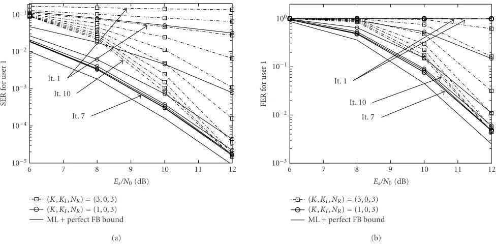
InFigure 6, the SER and FER performances of receiver 1 are presented versus per-antennaEs/N0, for (K,KI,NR)=
(3, 0, 3) andτ =0 with the iteration number as a parameter. In Figure 7, the same set of curves is given for the receiver 2. It is seen that the single-user bound can be achieved af-ter approximately 8 iaf-terations. It should be noticed that with (K,KI,NR) = (1, 0, 3), the performances of both receivers
after 5 iterations are within only 0.5 dB from the
It. 1 It. 10
It. 7
(K,KI,NR)=(3, 0, 3) (K,KI,NR)=(1, 0, 3) ML + perfect FB bound
6 7 8 9 10 11 12
Es/N0(dB)
10−5
10−4
10−3
10−2
10−1
SER
for
u
ser
1
(a)
It. 1 It. 10
It. 7
(K,KI,NR)=(3, 0, 3) (K,KI,NR)=(1, 0, 3) ML + perfect FB bound
6 7 8 9 10 11 12
Es/N0(dB)
10−3
10−2
10−1
100
FER
for
user
1
(b)
Figure7: Receiver 2’s performance versus per-antennaEs/N0; (K,KI,NR)=(3, 0, 3), (B,T)=(150, 15),NT =2,τ=0. (a) Symbol error
rate and (b) frame error rate. FB=feedback. It.=iteration index.
Figure 8shows SER and FER performances of both re-ceivers versus per-antennaEs/N0for (K,KI,NR)=(2, 1, 3). It
was assumed in this scenario that the UCCI uses only a single antenna. The simulation results for two values of signal-to-UCCI-interference ratio (SIR) are presented. In the cases of SIR equal to 3 dB and 0 dB, the power of the signal transmit-ted from the UCCI’s antenna was assumed to be the same as the power of the signal from the single and two anten-nas of any of the desired users, respectively. For comparison, the single-user bound described by (K,KI,NR)=(1, 0, 3) is
presented. It can be seen that both receivers are rather ro-bust against the presence of unknown interference in a wide range ofEs/N0values, for both SIR values. Moreover, in case
of SIR =3 dB, the receivers canperfectlysuppress the UCCI if theEs/N0value becomes large. This is due to the fact that
after convergence the receivers have enougheffectiveDoFs to separate and detect two desired users’ signals and suppress one UCCI. It can also be seen fromFigure 8that receivers 1 and 2 show very similar performance. This is due to the fact that the soft feedback is relatively reliable and preserving one additional DoF is of less significance.
InFigure 9, SER and FER performances of both receivers are presented versus per-antenna Es/N0 for (K,KI,NR) =
(2, 1, 3). In this scenario, the UCCI uses two antennas in the same way as the desired users. The curves are plotted with SIR, frame lengthB, and channel decay exponentτas param-eters. For comparison, the single-user bound described by (K,KI,NR)=(1, 0, 3) is also presented. It can be seen again
that both receivers are robust against interference over a wide range of Es/N0values. However, due to the lack of effective
DoFs, the performance curves tend to saturate an error floor
with highEs/N0 values. This can be solved in a
straightfor-ward manner by adding more receive antennas. However, it should be noted fromFigure 9that the error floor can be re-duced by increasing the frame length while keeping the ratio T/B constant. This behavior can be explained by two reasons: first, increasing the frame length results in more samples for
R estimation; second, the feedback becomes more accurate with the increased frame length.
It can also be seen by comparing the results forτ → 0 andτ → ∞fromFigure 9that the gain from using receiver 2 is larger if the number of significant multipath compo-nents is smaller. This is due to the fact that in the rich mul-tipath environment (τ →0), the number ofeffectiveDoFs is much smaller than the number needed to perfectly suppress the UCCI. Therefore, preserving one DoF with the receiver 2 does not have any significant impact on the receivers’ per-formance. On the other hand, in the flat fading, (τ → ∞) the number ofeffectiveDoFs is comparable to the number needed to suppress the UCCI, and preserving one DoF proves performance. The performances of both receivers im-prove with increased SIR and in the absence of UCCI they are expected to approach the corresponding single-user bounds.
6. CONCLUSIONS
It. 1
It. 13
Receiver 2, SIR=0 dB Receiver 1, SIR=0 dB Receiver 2, SIR=3 dB Receiver 1, SIR=3 dB (K,KI,NR)=(1, 0, 3) bound
5 7 9 11 13 15 17
Es/N0(dB)
10−4
10−3
10−2
10−1
SER
for
u
ser
1
(a)
It. 1
It. 13
Receiver 2, SIR=0 dB Receiver 1, SIR=0 dB Receiver 2, SIR=3 dB Receiver 1, SIR=3 dB (K,KI,NR)=(1, 0, 3) bound
5 7 9 11 13 15 17
Es/N0(dB)
10−3
10−2
10−1
100
FER
for
user
1
(b)
Figure8: Receiver 1’s and 2’s performance versus per-antennaEs/N0; (K,KI,NR)=(2, 1, 3), (B,T)=(150, 15),NT =2, SIR=0 and 3 dB
(single antenna used by UCCI),τ=0. (a) Symbol error rate and (b) frame error rate.
It. 1
It. 13
Receiver 2, SIR=0 dB, FRM1,τ=0 Receiver 1, SIR=0 dB, FRM1,τ=0 Receiver 2, SIR=3 dB, FRM1,τ=0 Receiver 1, SIR=3 dB, FRM1,τ=0 Receiver 2, SIR=0 dB, FRM2,τ=0 Receiver 1, SIR=0 dB, FRM2,τ=0 Receiver 2, SIR=3 dB, FRM1,τ→ ∞ Receiver 1, SIR=3 dB, FRM1,τ→ ∞ (K,KI,NR)=(1, 0, 3) bound
7 12 17 22 27
Es/N0(dB)
10−4
10−3
10−2
10−1
SER
for
user
1
(a)
It. 1
It. 13
Receiver 2, SIR=0 dB, FRM1,τ=0 Receiver 1, SIR=0 dB, FRM1,τ=0 Receiver 2, SIR=3 dB, FRM1,τ=0 Receiver 1, SIR=3 dB, FRM1,τ=0 Receiver 2, SIR=0 dB, FRM2,τ=0 Receiver 1, SIR=0 dB, FRM2,τ=0 Receiver 2, SIR=3 dB, FRM1,τ→ ∞ Receiver 1, SIR=3 dB, FRM1,τ→ ∞ (K,KI,NR)=(1, 0, 3) bound
7 12 17 22 27
Es/N0(dB)
10−3
10−2
10−1
100
FER
for
user
1
(b)
Figure9: Receiver 1’s and 2’s performance versus per-antennaEs/N0, (K,KI,NR)= (2, 1, 3), (B,T)= (150, 15) and (300, 30),NT =2,
detects only one antenna at a time. In the presence of rela-tively strong UCCI, the gain from joint detection is larger if the channel has less multipath components. This is due to the fact that preserving DoFs of the receivers with the joint detection has a greater impact on performance if the num-ber of effective DoFs is comparable to the number needed to perfectly suppress UCCI. The complexity of the MMSE part of the receiver is independent of the number of antennasn0
that are to be jointly detected. However, the complexity of the APP part, that calculates the extrinsic probabilities needed for SISO channel decoding, grows exponentially withn0. It
has been shown that the performance of both receivers im-proves by increasing frame length, due to the improved feed-back reliability. The performance also improves with higher SIR values. The gain from joint detection, however, is smaller if the feedback is more reliable.
In a multiuser scenario without UCCI, the proposed receivers can achieve corresponding single-user bounds. Thereby, the required number of receive antennas is equal to the number of users and not to the total number of trans-mit antennas. Furthermore, the receivers’ single-user perfor-mances are very similar to each other and relatively close to the performance of the ML receiver with perfect feedback.
Future work may include further receiver structure gen-eralization, where the antennas from more than one user are to be detected jointly. This would result in more DoFs that can be used for the UCCI cancellation. It is also of interest to determine the maximum number of usersKfor which the single-user bound can be achieved withNR =Kreceive
an-tennas withNTas a parameter. Further study is also required
to evaluate the receivers’ sensitivity to the spatial correlation. The joint detection is expected to be more robust than the antenna-by-antenna detection [29].
APPENDIX
Without loss of generality, derivation of the optimal pair [Wk1(i),Ak1(i)] of matrices is presented only for the first group ofn0jointly detected antennas. The derivation is
simi-lar for the other groups, with difference only in indexing. We denote thenth columns of the matricesWk1(i) andAk1(i) asw(n)anda(n), respectively. For simplicity of notation, we
omit the dependence ofw(n)anda(n) on user indexk,
an-tenna group indexγ, and time instanti. The cost function in (16) that is to be minimized can be written as
JWk1(i),Ak1(i)=E
This is equivalent to minimizing each of the component cost functions, defined as
J(n)m(n)=Em(n)Hg2. (A.4)
To avoid the trivial solution, [a(n)]
n is set to be equal to 1.
Introducing the Lagrange multiplier λ, the equivalent cost function to be minimized becomes
J(n)
Differentiating (A.5) with respect tom(n)gives
∂J(n)
From (A.7), the optimal value ofm(n)can be found as
m(n)= R
Applying the property of the inverse of the block-matrix [30]
from which it follows that
After repeating similar procedure for all then0transmit
an-tennas from the first group of thekth user, the optimal pair of matrices [Wk1(i),Ak1(i)] is obtained as
The authors gratefully acknowledge Nokia, Elektrobit, Finnish Air Forces, Instrumentointi, National Technology Agency of Finland (Tekes), Nokia Foundation, and Infotech Oulu Graduate School for their support and the anonymous reviewers for their helpful comments.
REFERENCES
[1] E. Telatar, “Capacity of multi-antenna Gaussian channels,” European Transactions on Telecommunications, vol. 10, no. 6, pp. 585–595, 1999.
[2] G. J. Foschini, “Layered space-time architecture for wireless communication in a fading environment when using multiple antennas,”Bell Labs Technical Journal, vol. 1, no. 2, pp. 41–59, 1996.
[3] S. M. Alamouti, “A simple transmit diversity technique for wireless communications,” IEEE Journal on Selected Areas in Communications, vol. 16, no. 8, pp. 1451–1458, 1998. [4] V. Tarokh, N. Seshadri, and A. R. Calderbank, “Space-time
codes for high data rate wireless communication: perfor-mance criterion and code construction,” IEEE Transactions on Information Theory, vol. 44, no. 2, pp. 744–765, 1998. [5] V. Tarokh, A. Naguib, N. Seshadri, and A. R. Calderbank,
“Space-time codes for high data rate wireless communication: performance criteria in the presence of channel estimation er-rors, mobility, and multiple paths,”IEEE Trans. Communica-tions, vol. 47, no. 2, pp. 199–207, 1999.
[6] Y. Gong and K. B. Letaief, “Performance evaluation and anal-ysis of space-time coding in unequalized multipath fading links,”IEEE Trans. Communications, vol. 48, no. 11, pp. 1778– 1782, 2000.
[7] L. Hanzo, W. Webb, and T. Keller, Single and Multicarrier Quadrature Amplitude Modulation, John Wiley & Sons, New York, NY, USA, 2000.
[8] L. R. Bahl, J. Cocke, F. Jelinek, and J. Raviv, “Optimal decod-ing of linear codes for minimizdecod-ing symbol error rate,” IEEE Transactions on Information Theory, vol. 20, no. 2, pp. 284– 287, 1974.
[9] C. Douillard, C. B. M. Jezequel, C. Berrou, A. Picart, P. Didier, and A. Glavieux, “Iterative correction of intersymbol interfer-ence: turbo-equalisation,”European Transactions on Telecom-munications, vol. 6, no. 5, pp. 507–511, 1995.
[10] G. Bauch and A. Naguib, “MAP equalization of space-time coded signals over frequency selective channels,” inProc. IEEE Wireless Communications and Networking Conference (WCNC ’99), vol. 1, pp. 261–265, New Orleans, La, USA, September 1999.
[11] G. Bauch and N. Al-Dhahir, “Reduced-complexity space-time turbo-equalization for frequency-selective MIMO channels,” IEEE Transactions on Wireless Communications, vol. 1, no. 4, pp. 819–828, 2002.
[12] B. L. Yeap, C. H. Wong, and L. Hanzo, “Reduced complexity in-phase/quadrature-phase turbo equalisation using iterative channel estimation,” inProc. IEEE International Conference on Communications (ICC ’01), vol. 2, pp. 393–397, Helsinki, Finland, June 2001.
[13] L. Hanzo, T. H. Liew, and B. L. Yeap, Turbo Coding, Turbo Equalisation and Space-Time Coding for Transmission over Fading Channels, John Wiley & Sons, Chichester, UK, 2002. [14] D. Reynolds and X. Wang, “Low-complexity
turbo-equal-ization for diversity channels,” Signal Processing, vol. 81, no. 5, pp. 989–995, 2001.
[15] X. Wang and H. V. Poor, “Iterative (turbo) soft interfer-ence cancellation and decoding for coded CDMA,” IEEE Trans. Communications, vol. 47, no. 7, pp. 1046–1061, 1999. [16] M. T¨uchler, A. C. Singer, and R. Koetter, “Minimum
mean squared error equalization using a priori information,” IEEE Trans. Signal Processing, vol. 50, no. 3, pp. 673–683, 2002.
[17] M. T¨uchler, R. Koetter, and A. C. Singer, “Turbo equalization: principles and new results,”IEEE Trans. Communications, vol. 50, no. 5, pp. 754–767, 2002.
[18] T. Abe and T. Matsumoto, “Space-time turbo equalization in frequency-selective MIMO channels,” IEEE Trans. Vehicular Technology, vol. 52, no. 3, pp. 469–475, 2003.
[19] H. Omori, T. Asai, and T. Matsumoto, “A matched filter ap-proximation for SC/MMSE iterative equalizers,” IEEE Com-munications Letters, vol. 5, no. 7, pp. 310–312, 2001.
[20] B. Lu and X. Wang, “Iterative receivers for multiuser space-time coding systems,”IEEE Journal on Selected Areas in Com-munications, vol. 18, no. 11, pp. 2322–2335, 2000.
[21] T. Abe, S. Tomisato, and T. Matsumoto, “A MIMO turbo equalizer for frequency-selective channels with unknown in-terference,” IEEE Trans. Vehicular Technology, vol. 52, no. 3, pp. 476–482, 2003.
[22] D. Reynolds and X. Wang, “Turbo multiuser detection with unknown interferers,” IEEE Trans. Communications, vol. 50, no. 4, pp. 616–622, 2002.
[23] J. Li, K. B. Letaief, and Z. Cao, “Adaptive cochannel inter-ference cancellation in space-time coded communication sys-tems,”IEEE Trans. Communications, vol. 50, no. 10, pp. 1580– 1583, 2002.
[25] A. F. Naguib, N. Seshadri, and A. R. Calderbank, “Applica-tions of space-time block codes and interference suppression for high capacity and high data rate wireless systems,” inProc. 36th Asilomar Conference on Signals, Systems & Computers, vol. 2, pp. 1803–1810, Pacific Grove, Calif, USA, November 1998.
[26] A. F. Naguib, V. Tarokh, N. Seshadri, and A. R. Calderbank, “A space-time coding modem for high-data-rate wireless com-munications,” IEEE Journal on Selected Areas in Communica-tions, vol. 16, no. 8, pp. 1459–1478, 1998.
[27] H. V. Poor and S. Verd ´u, “Probability of error in MMSE mul-tiuser detection,” IEEE Transactions on Information Theory, vol. 43, no. 3, pp. 858–871, 1997.
[28] S. Benedetto, D. Divsalar, G. Montorsi, and F. Pollara, “A soft-input soft-output APP module for iterative decoding of con-catenated codes,” IEEE Communications Letters, vol. 1, no. 1, pp. 22–24, 1997.
[29] N. R. Veselinovic, T. Matsumoto, and C. Scheider, “Reducing performance sensitivity to spatial correlation and timing off -set in space-time-coded MIMO turbo equalization,” to appear inIEICE Transactions on Communications.
[30] G. H. Golub and C. F. Van Loan,Matrix Computations, Johns Hopkins University Press, Baltimore, Md, USA, 2nd edition, 1989.
Nenad Veselinovicwas born in Valjevo, Ser-bia and Montenegro, in 1975. He received his M.S., in electrical engineering from the University of Belgrade, Belgrade, Serbia and Montenegro, in 1999. In 2000, he joined the Centre for Wireless Communications, Uni-versity of Oulu, Oulu, Finland, where he is currently working as a Research Scien-tist. Mr. Veselinovic is working towards the Ph.D. degree in the field of wireless
com-munications. His main research interests are in statistical signal processing and receiver design for broadband wireless communi-cations. He is a Student Member of the IEEE.
Tad Matsumoto received his B.S., M.S., and Ph.D. degrees in electrical engineer-ing from Keio University, Yokohama-shi, Japan, in 1978, 1980, and 1991, respec-tively. He joined Nippon Telegraph and Telephone Corporation (NTT) in April 1980. From April 1980 to January 1991, he researched signal transmission techniques, such as modulation/demodulation, error control, and radio link design schemes for
1st- and 2nd-generation mobile communications systems. In July 1992, he transferred to NTT DoCoMo, where he researched code-division multiple-access (CDMA) techniques. From 1992 to 1994, he served as a part-time lecturer at Keio University. In April 1994, he transferred to NTT America, where he served as a Senior Techni-cal Advisor in the NTT-NEXTEL Communications joint project. In March 1996, he returned to NTT DoCoMo, and he was appointed a Head of Radio Signal Processing Laboratory at NTT DoCoMo, where he researched adaptive signal processing, MIMO turbo sig-nal detection, interference cancellation, and space-time coding techniques for broadband mobile communications. In May 2002, he moved to the University of Oulu, Finland, where he is a Profes-sor at the Centre for the Wireless Communications. Presently, he is serving as a Board-of-Governor of the IEEE VT Society for a term from January 2002 to December 2004.
Markku Junttireceived his M.S. and Dr.Sc. degrees in electrical engineering from Uni-versity of Oulu, Oulu, Finland, in 1993 and 1997, respectively. Dr. Juntti has been with University of Oulu since 1992. In 1994– 1995, he was a Visiting Research Scientist at Rice University, Houston, Texas. In 1999– 2000, he was with Nokia Networks as a Se-nior Specialist. Dr. Juntti has been a Profes-sor of Telecommunications at University of