R E S E A R C H
Open Access
Target maneuver discrimination using ISAR
image in interception
S.-J. Fan
1*, H.-T. Xiao
1, H.-Q. Fan
1and J.-P. Fan
2Abstract
Discrimination for target maneuver magnitude and direction switching during the endgame is significant for interception performance improvement. Inverse synthetic aperture radar (ISAR) images carry the information related to target motion parameters. It is feasible to use them to discriminate the maneuver. An imaging model in interception is first formulated. The principle of maneuver discrimination using the ISAR images is then fully explored. A novel and practical discriminator is developed with a rigorous analysis of the scenario characteristics. The discriminator parameter selection and some important factors affecting the discrimination performance are discussed comprehensively. Finally, a simulation environment with software tools capable of generating target-realistic ISAR images is developed. The simulation results confirm the rationality of the design procedure and demonstrate that the proposed discriminator performs better than the classical innovation-based maneuver discriminator.
Keywords: Maneuver target, Motion discrimination, Inverse synthetic aperture radar, Interception
1 Introduction
The interception of highly maneuver target is a repre-sentative optimal control problem, and target maneuver is one of the main error sources for the nonzero miss distance as the guidance theory points out [1]. Fast re-sponse to a maneuver onset and exact discrimination of the acceleration change are important for interception performance improvement. Since target maneuvers are independently controlled and target acceleration cannot be measured directly by existing sensors, acceleration can only be acquired by means of state estimation.
Conventional works commonly adopt the acceleration magnitude change from zero to nonzero as the maneu-ver indication [2, 3]. Howemaneu-ver, a large amount of simula-tion studies and flight tests have demonstrated that maneuvering in a fixed direction (constant acceleration, denoted as type I maneuver) does not, usually, pose a real challenge to the interceptor guidance system. Ra-ther, the more difficult problem (handled by the target acceleration estimator) is to detect a single, randomly timed maneuver direction switch (MDS) during the
endgame [4] (denoted as type II maneuver). It was also found that such a bang-bang type of evasion maneuvers is the optimal one for interception avoidance [1, 5]. Hence, we focus on the maneuver discrimination for a single MDS in interception in this paper.
According to the information employed in the maneu-ver discriminator, current techniques can be mainly classified into two categories: innovation-based and feature-based. The innovation-based [6] maneuver de-tector and state estimator depend on the innovation in-formation of the Kalman filter or its variation. Whether a single-model or multiple-model method, it is difficult to achieve a short discrimination delay while maintain-ing high correct probabilities, due to the Q effect [2]. This inherent drawback becomes more serious when a mismatch occurs between target acceleration and prede-signed models. By employing maneuver information em-bedded in the features from sensors, the feature-based technique [6] breaks through the above obstacle. In an air-to-air interception scenario, the bank angle measure-ment from the image is utilized in estimator when the fighter plane is taking a bank-to-turn (BTT) maneuver [4]. The detection delay is greatly reduced compared to the classical innovation-based estimator. Many similar researches exploit maneuver information from optical * Correspondence:[email protected]
1ATR, National University of Defense Technology, Changsha 410072, People’s Republic of China
Full list of author information is available at the end of the article
sensors by estimating target orientation directly [7] or extracting image fluctuant features indirectly [8]. How-ever, the target range and velocity cannot be measured by optical sensors directly which are helpful for the state estimation and guidance. The radar echo also conveys maneuver information due to the modulation effects on electromagnetic scattering, and it can easily handle the problems of the optical sensors. Some narrowband radar features including glint, radar cross section (RCS), and high-resolution Doppler profile (HRDP) have been exploited successfully for type I maneuver detection [6, 9, 10]. But the MDS discrimination is not involved in the aforementioned researches. The validity of these approaches needs to be further verified.
According to the information employed in the maneu-ver discriminator, current techniques can be mainly clas-sified into two categories: innovation-based and feature-based. The former methods depend on the innovation information of the Kalman filter or its variations [6]. Due to the Q effect [2], it is difficult for both of the single-model and multiple-model methods to achieve a short discrimination delay while maintaining high cor-rect probabilities. This inherent drawback becomes more serious with mismatch between target acceleration and predesigned models. However, employing maneuver in-formation embedded in the features from sensors, feature-based techniques [6] overcome the above obs-tacle. For instance, in an air-to-air interception scenario where a fighter plane is taking a BTT maneuver [4], an estimator using the bank angle measurement from im-ages can greatly reduce the detection delay, compared to the classical innovation-based estimator. Many similar researches exploit maneuver information from optical sensors by directly estimating target orientation [7] or indirectly extracting image fluctuant features [8]. Unfor-tunately, optical sensors cannot directly measure target range and velocity which are helpful for the state estima-tion and guidance. Radar sensors can also capture man-euver information and easily obtain target range and velocity, because of the modulation effect on electro-magnetic scattering. Narrowband radar features includ-ing glint, RCS, and HRDP have been exploited to detect type I maneuver [6, 9, 10]. But their validity needs to be further verified for the MDS discrimination, which is not involved in the aforementioned researches.
Generally, compared with low-resolution radar fea-tures, high-resolution features from high-range reso-lution (HRR) or inverse synthetic aperture radar (ISAR) images gain more advantages in maneuver information extraction. As stated in [11], the relative orientation of missile-to-target in interception can be approximated by a turntable model, which makes the maneuver discrim-ination using ISAR images possible. In fact, the estima-tion of moestima-tion parameters per se including translaestima-tional
motion velocity, rotation velocity, and direction is key to autofocus and cross-range scaling in ISAR imaging, and many signal-domain and image-domain methods have been proposed [12–15]. In essence, these methods are mostly offline data processing regardless of application backgrounds and need an iterative optimization“ match-ing.” Notice that they comprehensively do not analyze the relationship between maneuver parameters and ISAR images as well as the impact factors on estimation error, such as resolution and relative orientation of missile-to-target. Yang et al. [16] derive the relationship between target ISAR image slope and turn rate in the ground moving target indicator (GMTI) radar surveillance. In this paper, we extend the air-to-ground scenario to an air-to-air interception scenario and estimate the lateral acceleration instead of the maneuvering turn. Moreover, the estimation in a quasi-steady state is extended to the transient period with a determination of maneuver switch instant.
Considering the interception of a skid-to-turn (STT) cruise missile taking a horizontal, planar “S” maneuver (denoted as type II maneuver) in penetration [17, 18], the sideslip angle will change, and a novel and practical target maneuver discriminator using ISAR images is pro-posed with rigorous analysis. For simplicity, we assume the target translational motion is well compensated, and employ the image-domain features, in consideration of the effect of echoes’quality on the signal-domain param-eter estimation. The paper makes an elaborate and systematic analysis of the maneuver discrimination principle in Section 2. Section 3 discusses some import-ant factors affecting the discrimination performance and then proposes a maneuver discriminator using ISAR im-ages. Simulation results are presented in Section 4, and conclusion is drawn in Section 5.
2 Maneuver discrimination principle
Taking the initial line-of-sight (LOS) coordinate system as the inertial coordinate system, the geometry of the two-dimensional interception scenario is shown in Fig. 1, where Ris the distance between target and missile,q is the LOS angle, and γM, aM, and VMand γT,aT, andVT
are missile and target path angles, accelerations (perpen-dicular to the respective velocities), and speeds, respect-ively. Assuming first-order dynamics for both target and missile and both velocities are nearly constant, the fol-lowing dynamics equations are satisfied:
relationship between motion parameters and relative orientation of missile-to-target in a three-dimensional interception scenario has been derived in [11]. A two-dimensional simplified analysis is presented to establish the ISAR imaging model as follows.
2.1 Imaging model
A right-handed coordinate system is attached to the target where the x-axis is pointing out of the nose, the y-axis to the left, and the z-axis to the top. Assuming the target velocity is along the x-axis, the pose angleψ, relative to LOS, and its ratesωare formulated as
ψ¼γT−q
ω¼ ψ:¼γ:T−q: ð
2Þ
The positive pose angle is prescribed to the left and the positive turn is also to the left. The considerable dis-parities of ψ and ω in MDS are the basis of maneuver discrimination. In (2),γ::Tandq::represent the pose angle variety introduced by the target motion and relative motion of missile-to-target, respectively. It has been demonstrated in [11] that
: q
j j≪γ::T : ð3Þ
This conclusion also can be explained by the ex-pression of :q: in proportional navigation (PN) guid-ance law [19]:
:
q¼VTsinðγT−qÞ−VMsin γM−q
R : ð4Þ
In fact, the numerator of (4) is the “collision triangle” (the dotted triangle in Fig. 1) condition [19]. If the rela-tive motion keeps the condition satisfied in the whole interception, i.e.,VTsinðγT−qÞ ¼VMsin γM−q
; :q¼0 is straightforward. In real interception scenario,q: is influ-enced by many factors, including target maneuver, guid-ance law adopted, initial heading error, and estimation error. But the guidance law always keepsq: within a small neighborhood of zero before the seeker head reaches its
blind range. Hence, after translational motion compensa-tion, the imaging model in two-dimensional interception can be approximated as a planar rotating object in Fig. 2, where rotation angular velocity is equal to the pose angle rate,
ω¼ψ:≈γ:T ð5Þ
Furthermore, assuming target centroidOas the origin, the scatterer on target of radial distanceLis mapped on to the range-Doppler plane as follows under the far-field condition:
X ¼Lcosψ=ηr
Y ¼−λ2v=ηf ¼
−2ωLsinψ
λ =ηf; ð6Þ
where v is the rotation linear velocity, λ is the wave-length, andηrandηf are the range and Doppler resolu-tions, respectively, defined by
ηr¼c=ð Þ2B ηf ¼1=Timg: ð7Þ
In (7), c is the velocity of light, B is the signal band-width, and Timg is the imaging time. A typical target
ISAR image is also illustrated in Fig. 2 which shows the scatterer distribution in the range-Doppler plane.
The above imaging model in interception differs sig-nificantly from that in surveillance of the ground-based radar (or other location-fixed radar) [6, 16]. In the latter situation, an ISAR image also can be obtained even if the target does not maneuver. However, from Fig. 2, we can see that only when the target takes the lateral maneuver (perpendicular to velocity), i.e., rotation, the imaging condition could be satisfied. This disparity pro-vides the feasibility of maneuver discrimination using ISAR images in interception.
2.2 Relationship between maneuver parameters and images
The changes of target acceleration aT and acceleration
commandacTin type II maneuver are showed in Fig. 3.
In maneuver discrimination, we focus on the acceler-ation command switch instant tsw and the acceleration
direction switch instant tdir. tsw is usually set to be the
starting instant which is the reference to the discrimin-ation delay evaludiscrimin-ation. We follow this metric in our paper. By substituting (1) into (5),ωand its time deriva-tive can thus be expressed as
ω¼aT=VT
:
ω¼ acT−aT
=VTτT: ð
8Þ
From (8),ωand :ω:encapsulate the full information of target maneuver. On the other hand, from (6),ω can be derived by the scatterer position in the range-Doppler plane. Consequently, the maneuver information can be extracted theoretically by matching the target scatterers in ISAR images of different instants [13, 14]. For example [14], ω of airplane rotation is estimated by comparing the geometrical relationship differences of relative scatterers in two adjacent images. Actually, the
equivalent scatterer number of missile-class target is sig-nificantly fewer than ship or airplane due to its smaller size. So the matching process needs the high-resolution images, and the scatterer association in different images must be well-handled. Fortunately, a“shaft-like”shape is available for extracting the line features from target ISAR images.
From (6), the slope of the target ISAR image can be expressed as
s¼X Y ¼−
fs
Timgf0ωtanψ
¼ω K
tanψ; ð9Þ
where f0is the center frequency and K=−fs/Timgf0 is a known constant. By substituting (8) into the time deriva-tive ofs, we obtain
: s:¼ −K
sinψ
: ω:
ω2 cosψþ 1 sinψ
!
: ð10Þ
Thus, the relationship betweensandω, also their time derivatives, is established. It is noted that these relation-ships are also related to the pose angle ψ. We firstly as-sume ψ> 0 in the following analysis and other situations are discussed later.
For the sake of clarity, type II maneuver is further vided into two types considering the different switch di-rections, i.e., type P and type N. According to Fig. 3, a detailed summary of maneuver parameters and slope features in type II maneuver is listed in Table 1.
sin2ψ> −2a 2 TτT −amax
T −aT
VT
; ψ>0 ð11Þ
According to the results summarized in Table 1, we can see that the value of s: and the sign of s will change after the time instants tsw and tdir,
respect-ively. Especially, if ψ satisfies (11) in the type P Fig. 2Imaging model in two-dimensional interception
maneuver, the MDS can be easily discriminated only by the sign of s::.
Notice that the above derivation entails the assump-tion that the rotaassump-tion center of the target is known which is very difficult to fulfill in reality. As a matter of fact, the slope estimation can be realized by any two scatterers along the target radial axis or by some elabor-ate line-extraction algorithms in image processing. Both of them are independent of the position of rotation cen-ter. More detailed scheme will be given in the next section.
2.3 Discussion
We discuss the influence ofψon the maneuver discrim-ination performance herein. As we know, most of the missile targets are of axial symmetry. The ISAR image acquired whenψ< 0 andω< 0 is the same as that when
ψ> 0 and ω> 0 according to Fig. 2. In other words, we only have the information of |ψ| and |ω| from the ISAR images. Thereupon, some further remarks are made as follows (the sign of variable is denoted as sgn[⋅] for simplicity):
First of all, conclusions in Table 1 are contrary when
ψ< 0 according to (9) and (10). It does not affect the de-tection oftswbut misleads the MDS discrimination.
Ac-tually, sgn[s] only indicates whether the target is turning toward or away from the LOS without the knowledge of sgn[ψ].
Secondly, if ψ traverses zero in interception, either +→0→−or−→0→+, a “ghost phenomenon” is pro-duced which meansω changing from ω< 0 to ω> 0. As a result, both sgn[s] and the value ofs: vary even though no MDS occurs. In this instance, the discrimination of type N maneuver suffers from the invalidation or ambiguity.
Thirdly, from the expression ofs: before the MDS oc-curs, i.e., s:¼ −K
sin2ψ, we know that the value of s: varies
along withψ even there is no MDS. If the value ofs: is used as the test statistic, a float threshold is needed which is generated by a large amount of statistics at dif-ferentψ. But it is very hard to be realized in reality.
Finally, the performance of line extracting from the images strongly depends on the value ofψ. For example,
within a small neighborhood of ψ= 0, the target image approximately remains perpendicular to the Doppler axis even if there is a rotation. The reason is that Doppler frequencies developed in both sides of a target from the front to the rear have the same small values with different signs. At the same time, the ISAR image spreads in several Doppler resolution bins due to the target width. Therefore, both sgn[s] and the value of s:: variations are unpredictable results from the line extract-ing errors.
In summary, the estimation of sgn[ψ] and a de-ambiguity processing are necessary for the former two situations in maneuver discrimination. From the point of an implementation view, only sgn½ s: and sgn[s] are se-lected in our paper as the indications of MDS. Although (11) should be satisfied in type P maneuver, it holds in most cases during [tsw,tdir]. This situation will be
testi-fied in Section 4 where the effect ofψon discrimination performance is also explained more thoroughly.
3 Discriminator design
3.1 Image pre-processing
The ISAR image series can be obtained by the sliding windowing method. The window length, i.e.,Timg,
deter-mines the accumulated rotating angle for each ISAR image, and thus determines its Doppler resolution (inversely proportional toTimg in (7)). But longTimg
im-plies great delay in discrimination. Hence, a tradeoff be-tween delay and resolution should be considered. On the other hand, the sliding step length (denoted as ΔT) determines the aspect angle difference between neigh-boring ISAR images with a givenω. In reality,ΔTshould be less than the missile control period but not too small. If so, the estimation of:s: is not reliable due to the slight difference between neighboring aspect angles.
Then, a target image is segmented out from the scene that is indicating which pixels are on-target. This usually can be done using CFAR detection followed by a sequence of binary morphological oper-ations [16]. For the air-to-air endgame application in our paper, the signal-to-noise ratio (SNR) is quite high due to the low clutter and the enough radiation power. The major noise sources are scatterer amplitude Table 1The summary of maneuver parameters and slope features in type II maneuver (ψ> 0)
and position fluctuations. So the target is segmented sim-ply by the following two level thresholds:
TH1¼I xð ;yÞ
――――
¼XND
j¼1
XNR
i¼1
I xi;yj
=NDNR
TH2¼C⋅X
ND
j¼1
XNR
i¼1
I′ xi;yj
;
ð12Þ
where I(xi,yj) is the original image pixel value, ND and
NRare the numbers of pixels in the Doppler and range directions, respectively, I′(xi,yj) is the image pixel value
filtrated by the first-level threshold TH1, and C< 1 is a scaling factor.
3.2 Estimation ofsands:
Many methods in curve fitting, image processing, and ISAR cross-range scaling can be utilized to estimate s [12–15]. Least squares (LS) and total least squares (TLS) methods are easy to operate but would be invalided if some shadowing or obstructions appeared in the ISAR
image [20]. Some algorithms such as Radon and Hough transforms [13] and polar mapping [15] can solve this problem by an iterative optimization implementation of exhaustive searching in a wide angle range. However, they afford heavy computational burden for real-time missile-borne application.
As analyzed earlier, only sgn[s] and sgn½ :s: are needed in most cases. Herein, the major axis direction in the image-domain analysis is used as the estimation of s [21], namely
^s¼ tanα¼ tan 1 2tan
−1 2μ11
μ20−μ02
; ð13Þ
whereαis the oblique angle,μpqis the (p+q)‐th central
moment of image defined as
μpq ¼ XND
j¼1
XNR
i¼1
xi−x
ð Þp
yj−y
q
I xi;yj
;
x¼m10
m00; y¼
m01
m00 p;q¼
0;1;2…
ð14Þ
and mpq is the (p+q)‐th geometrical moment of image
defined as
mpq ¼ XND
j¼1
XNR
i¼1
xipyqjI xi;yj
; p;q¼0;1;2… ð15Þ
From (13) to (15), we see that the major axis direction can be obtained only by some multiplications and additions in one cycle. The estimation ofs::, denoted ass^:: can be deduced by two neighboring frames of image sequence.
3.3 Estimation ofψ
With the knowledge of sgn[ψ], the real maneuver switch direction could be confirmed. An estimation method of
ψbased on the target velocity vector vTand LOS vector ris proposed in [16], namely
^
ψ ¼ cos−1 h^r^;^vTi
RV^T
: ð16Þ
From (16), we know that the accurate estimation is not well because both the position and velocity of missile-to-target need to be estimated. As mentioned
previously, the “collision triangle” condition holds ap-proximately in the whole interception.ψ^ can also be ob-tained by this restriction
^
ψ ¼ sin−1 V^M^sinγ^M
VT
ð17Þ
The target state estimation per se is quite accurate, so only the constant target speed needs to be estimated. Obviously, the estimation error of (17) is much smaller than that of (16).
3.4 De-ambiguity
In theory, the value ofψ^ can be used to solve the ambi-guity caused by the ghost phenomenon as mentioned in type N maneuver. But the estimation delay still exists from (17) because it is essentially an innovation-based method. It is difficult to solve the ambiguity based on the value of ψ^. Although there is no MDS, it is noted that |ω| is maximal duringψtraversing zero, and thus ŝ is quite accurate due to the high Doppler resolution. Therefore, if a change of sgn[ŝ] from positive to negative is detected, current frame or several frames before can be utilized to obtain an ŝ. The value of ŝ depends on ψ Fig. 5Block diagram of simulation environment
Table 2Parameters of simulation environment
Parameter Value
Target Motion VT¼300 m=s;amaxT ¼15g;τT¼0:2 s
Size Length = 5 m, width = 1 m
Missile Motion VM¼450 m=s; amaxM ¼20 gτM= 0.2 s,Tc= 0.01s
Radar λ= 3 cm, PRF = 32 kHzNp= 64,Δf= 10 MHz,B= 640 MHz
Scenario R0= 2.25 km,γT(0)∼U(−15∘, 15∘)
when MDS occurs, but it is almost constant when ψ is traversing zero. This disparity provides a feasible way to solve the ambiguity.
Finally, the flow chart of the proposed maneuver dis-crimination scheme is provided in Fig. 4.
Figure 4 shows that a two-stage detection is imple-mented employing sgn½^s: and sgn[ŝ] at different instants tswandtdir, respectively. Meanwhile, in order to increase
the reliability of ^s:, a “binary integration detection” or
“NB/MB detection” scheme is adopted [22]. The
detec-tion of sgn½^s: and sgn[ŝ] can be directly used as the indi-cation of tsw, whether the target is turning toward or
away from the LOS. Afterψ^ is integrated, the real man-euver switch direction (denoted asDin Fig. 4) is taken.
4 Simulation results
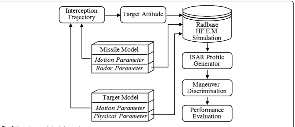
4.1 Simulation environment
The block diagram of simulation environment is shown in Fig. 5. A trajectory is generated in a missile-target interception scenario, and the target pose angle is calcu-lated. The scatterer phase center data, that is, the pos-ition and complex RCS of each of the scatterers composing the target in different pose angles and fre-quencies, are obtained through the high-frequency elec-tromagnetic simulation software RadBase [6]. Based on it, the ISAR images are generated considering the noise and clutter data. Finally, the performance of the maneu-ver discrimination is evaluated.
The simulation parameters are listed in Table 2, and the final time of the interception is about 3 s. The initial target heading angle uniformly distributed between ±15°, that means the missile is located in the head-on zone of the target. The differential game guidance laws (DGL1) and the step-frequency wideband waveform [23] are adopted by the missile. Regardless of the specific per-formance of estimator used, only the target acceleration estimation delay is considered, namely, Δest= 0.2 s. Esti-mation errors of other target states are assumed as the white Gaussian noises whose standard deviation is also listed in Table 2. Besides, the window sliding step length is set equal to the missile control period, namely, ΔT=Tc= 0.01 s.
4.2 Simulation results 4.2.1 A single run trial
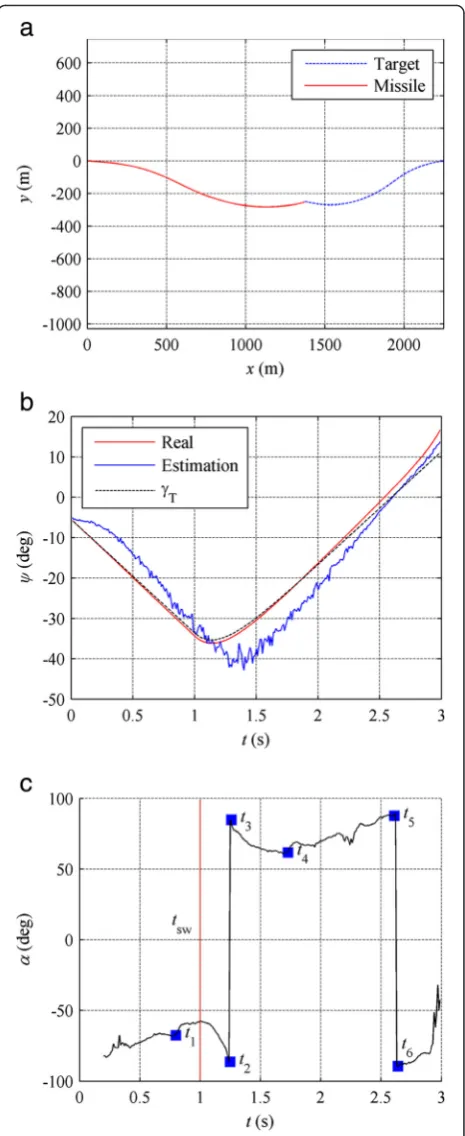
A single simulation run of missile-target interception trajectory is depicted in Fig. 6a, where the target per-forms a single MDS from −15 to 15 g at tsw= 1 s.
Figure 6b illustrates the pose angleψand the target path angleγTduring the whole interception. Note thatψ≈γT is almost satisfied except at the last phase when the LOS angle q variations are considerable. So the planar rota-tion imaging model is reasonable in interceprota-tion. The
estimation result of ψfrom (17) is also added in Fig. 6b. It can be seen that the estimation delay is evident, but the sign estimation is quite accurate.
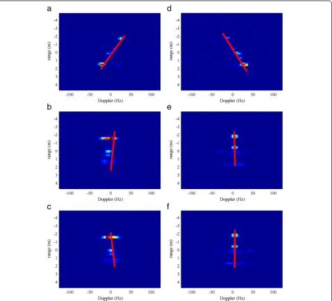
On the other hand, the oblique angle α in (13) in-stead of ŝ is shown in Fig. 6c for clarity, where six sample time instants are marked in turn. The ISAR images and ŝ corresponding to these time instants are illustrated, respectively, in Fig. 7. The imaging time Timg= 0.2 s and SNR = 10 dB [24] are prescribed in
ISAR imaging. Combined with the variation of ψ in Fig. 6b, some cases are outlined below: in these im-ages, most of target scatterers are visible due to the fast rotation rate (|ω|≈28∘/s at Fig. 7a, d), so the tar-get is turning about 5.6° in each imaging time inter-val. It makes easier to estimate the slope of the target. In the neighborhood of tdir (Fig. 7b, c), the
Doppler resolution degradation may adversely affect the accuracy of ŝ, but sgn[ŝ] reverses rapidly yet;
sgn[ŝ] also reverses from positive to negative when
ψis traversing zero (Fig. 7e, f ), but the Doppler resolution is distinctly higher than that in Fig. 7b, c. Another remark-able and important thing is the persistent decrement ofŝ during [tsw,t2] in Fig. 6c. That is to say, sgn½^s: reverses
after MDS occurs. All of these cases are consistent with the analysis and discussion in the above sections.
4.2.2 Discriminator parameter design
As analyzed earlier, the discriminator parameter design strongly depends on ψ. So the influence of various dis-criminator parameters on discrimination performance is testified through a large amount of Monte Carlo simula-tions at different ψ. Note that type P maneuver in ψ> 0
is equivalent to type N maneuver inψ< 0 and vice versa. Hence, only the target takes a single MDS from 15 to −15 g is considered. In simulation, the angle interval is 5° and 1000 runs at each interval are picked out by changing tsw and γT(0). From the point of
implementa-tion view, γMshould be smaller than the seeker gimbals angle [25] (35° in this paper) to make sure that the target will not fly off the field of view. Herein,ψ is limited to 60° according to the“collision triangle”condition.
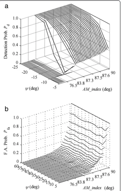
Figure 8 shows the detection probability Pd and the
false alarm probability Pfa oftswfor NB/MBdetection of ^
:
s: when Timg= 0.2 s. The detection performance
de-grades when ψ< 15∘ because the estimation errors of s increases and (11) is hardly to be satisfied. Both the de-tection and false alarm performance are good after ψ> 30∘. Since the detection of^s:is just the first stage of MDS discrimination, the minimalPfais the top priority for the
NB/MB selection. On the other hand, considering the
delay increases asNBandMBincrease, theNB/MB
selec-tion is a tradeoff between the delay andPfa.
Similarly, the performance of de-ambiguity is shown in Fig. 9. As mentioned in Section 3.4, the mean value ofα of ten frames before sgn[ŝ] changes from positive to negative is chosen as a threshold (denoted as AM_in-dex). In Fig. 9a, a cluster of the detection probability of type N maneuver (type P maneuver when ψ< 0) at different thresholds is exhibited. In contrast, the curves of false alarm probability in type P maneuver whenψ> 0 are illustrated in Fig. 9b. Different from the NB/MB
se-lection, the AM_index selection should pursue a total maximum sum ofPd−Pfa.
At last, the detection probability of different window lengths is shown in Fig. 10. The imaging time Timg is
normalized by the window sliding step length ΔT, for simplicity, namely, WL =Timg/ΔT. TheNB/MBis all“7/7”
and the AM_index values are 65.88∘, 87.2∘, and 87.5∘, respectively, in three cases. The detection probability of WL = 10 (Timg= 0.1 s) is low due to the low Doppler
reso-lution. The detection probability of WL = 15 and WL = 20 are closer, but WL = 15 is a better choice due to a smaller
delay. It is also apparent that the discrimination per-formance is extremely poor in the neighborhood of
ψ= 0 ([−5∘, 5∘]) that justifies the conclusion in the
former section.
4.2.3 Discrimination statistics
The total discrimination performance attsw∈[0.2, 2.8] s
in interception is shown in Fig. 11, and sets of 1000 Monte Carlo runs with random noise, random initial po-sitions at each time interval are used. The window length WL = 15 and other discriminator parameters are the same as given in Fig. 10. The detection probability Pd, false alarm probability Pfa, miss probability Pm, and
correct direction discrimination probabilityPc(integrated
sgn½ ) are illustrated in Fig. 11a. It can be seen that theψ^ total successful discrimination probability in interception is quite good with the exception of tsw= 2.8 s. Since the
sufficient information cannot be collected to deliver a statistically significant decision at this time instant when WL = 15, Pm increases rapidly. Besides, the performance
degrades slightly, especiallyPc<Pd, whentsw< 1 s, because
the pose angle ψ is often in the neighborhood of zero when MDS occurs.
From Fig. 11b, the minimum discrimination delay is 0.07 s which is acquired by the “7/7” detection of^s: and the maximum delay does not exceed 0.26 s. The mean delay keeps about 0.15 s at all switch instants. Compared with the classical innovation-based maneuver detector, such as adaptive-H0 and the standard GLR detectors in [26], the mean delay in the same detection probability is an almost linear function of tsw monotonically
decreas-ing from 0.35 (attsw= 0.2 s) to 0.16 s (attsw= 0.8 s). The
reason can be attributed to the constant angular noise, and the displacement noise is proportional to the range. The results are not shown here for conciseness.
Fig. 10The detection probability vs. different window lengths
Fig. 11The discrimination performance vs. switch time instanttsw.
aProbabilities.bDelay
4.2.4 Applicability summary
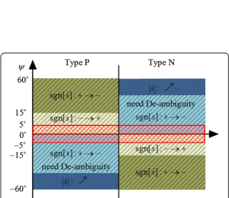
According to the pose angle ψ and maneuver type, an applicability summary of the proposed discriminator based on the analysis and simulation results is illustrated as follows:
From Fig. 12, the feature or the test statistics used in the discriminator are the same in the same color zone and the deeper color means the shorter delay. In reality, MDS often occurs in the hatch zone due to the initial head-on geometry of missile-to-target and the short fly time in endgame, so sgn[s] and sgn½ s: are sufficient for discrimination. The upper bound is determined by the gimbal angle of missile under the “collision triangle” condition, and the lower bound depends on the estima-tion error of s(the red mesh boundary). Of course, real switch direction discrimination and de-ambiguity are ne-cessary with the help of other information. Note that the applicability analysis in Fig. 12 is based on the particular scenario in this paper. Generally, the feature selection and the discriminator parameter design should be closely associated with the application characteristics.
5 Conclusions
Discriminating target maneuver using ISAR images is feasible because of the embedded information related to target motion parameters. This paper firstly sets up the imaging model in interception and mathematically derives the relationship between the bang-bang type maneuver parameters and ISAR image slope. Then, the principle of maneuver discrimination using the ISAR images is explored, and some important factors affecting the discrimination performance are discussed. A novel and practical discriminator is developed afterwards whose parameter is designed elaborately based on the endgame scenario characteristics. Finally, the simulation results give some operational guidelines to designer for choosing discriminator parameters in practice and demon-strate that the proposed discriminator performs better than the classical innovation-based maneuver discriminator.
Compared with the conventional maneuver detector, the proposed discriminator further provides the maneu-ver direction switch information which has been suc-cessfully used in both estimator [4] and guidance law [27]. In fact, as analyzed in this paper, we know that ω can be estimated directly from ISAR images or inte-grated in the conventional innovation-based estimator. It will certainly enhance the estimation performance. Moreover, although the analysis in this paper is based on STT maneuvering target, it is also feasible to extract the maneuver parameters for a BTT target. For example, the wings’rotation when the plane is taking a BTT maneu-ver is similar to the missile body’s rotation. In this situation, maneuver discrimination based on the ISAR images is a very attractive research direction.
Competing interests
The authors declare that they have no competing interests.
Acknowledgements
This work was supported in part by the China National Science Foundation under Grant 61101186 and the Specialized Research Fund for the Doctoral Program of China Higher Education under Grant 20134307110012. The authors thank Dr. Zhou J. X. for her valuable suggestions. The authors would also like to thank the anonymous reviewers for their valuable suggestions on improving this paper.
Author details
1ATR, National University of Defense Technology, Changsha 410072, People’s Republic of China.2College of Electronic Science and Engineering, National University of Defense Technology, Changsha 410072, People’s Republic of China.
Received: 13 September 2015 Accepted: 3 February 2016
References
1. J Shinar, T Vladimir, What happens when certainty equivalence is not valid? Is there an optimal estimator for terminal guidance? Annu. Rev. Control. 27, 119–130 (2003). doi:10.1016/j.arcontrol.2003.10.001
2. HQ Fan, S Wang, Q Fu, Survey of algorithms of target maneuver detection. Syst. Eng. Electron.31(5), 1064–1070 (2009)
3. JF Ru, VP Jikov, XR Li, A Bashi, Detection of target maneuver onset. IEEE Trans. Aerosp. Electron. Syst.45(2), 536–554 (2009)
4. Y Oshman, D Arad, Enhanced air-to-air missile tracking using target orientation observations. AIAA J Guid. Control. Dyn.27(4), 595–606 (2004). doi:10.2514/1.11155
5. J. Shinar, T. Shima, Robust missile guidance law against highly maneuvering targets. Paper presented at the 7th Mediterranean conference on control and automation, Haifa, Israel, 28–30 June 1999
6. YL Zhu, HQ Fan, JP Fan, ZQ Lu, Q Fu, Target turning maneuver detection using high resolution Doppler profile. IEEE Trans. Aerosp. Electron. Syst. 48(1), 762–779 (2012). doi:10.1109/TAES.2012.6129669
7. DD Sworder, RG Hutchins, Maneuver estimation using measurements of orientation. IEEE Trans. Aerosp. Electron. Syst.26(4), 625–638 (1990) 8. S Shetty, AT Alouani, A multisensor tracking system with an image-based
maneuver detector. IEEE Trans. Aerosp. Electron. Syst.32(1), 167–181 (1996) 9. EJ Hughes, M Leyland, Target manoeuvre detection using radar glint.
Electron. Lett.34(17), 1695–1696 (1998)
10. H.Q. Fan, Dissertation, National University of Defense Technology, 2008 11. SJ Fan, HQ Fan, HT Xiao, JP Fan, Q Fu, Three-dimensional analysis of
relationship between relative orientation and motion modes. Chin. J. Aeronaut.27(6), 1495–1504 (2014). doi:10.1016/j.cja.2014.10.016
12. ZW Xu, L Zhang, MD Xing, Precise cross-range scaling for ISAR images using feature registration. IEEE Trans. Geosci. Remote Sens. Lett.11(10),
1792–1796 (2014). doi:10.1109/LGRS.2014.2309604
13. CM Yeh, J Xu, YN Peng, XT Wang, J Yang, XG Xia, Cross-range scaling for ISAR via optical flow analysis. IEEE Aerosp. Electron. Syst. Mag.27(2), 14–22 (2012). doi:10.1109/MAES.2012.6163609
14. CM Yeh, J Xu, YN Peng, XM Shan, Rotational motion estimation for ISAR via triangle pose difference on two range-Doppler images. IET Radar. Sonar. Navig.4(4), 528–536 (2010). doi:10.1049/iet-rsn.2009.0042
15. SH Park, HT Kim, KT Kim, Cross-range scaling algorithm for ISAR images using 2-D Fourier transform and polar mapping. IEEE Trans. Geosci. Remote Sens.49(2), 868–877 (2011). doi:10.1109/TGRS.2010.2060731
16. C. Yang, W. Garber, R. Mitchell, E. Blasch, A simple maneuver indicator from target range-Doppler image. Paper presented at the 10th international conference information fusion, Quebec, Canada, 9–16 July 2007 17. B Etkin, LD Reid,Dynamics of Flight: Stability and Control(Wiley, New York, 1996) 18. J.R. Cloutier, T.S. Donald, Nonlinear hybrid bank-to-turn/ skid-to-turn missile
autopilot design. Paper presented at the AIAA guidance, navigation, and control conference and exhibit, Montreal, Canada, 6–9 August 2001, 705–715 19. NF Palumbo, RA Blauwkamp, JM Lloyd, Modern homing missile guidance
theory and techniques. J. Hopkins APL Tech. Dig.29(1), 42–59 (2010) 20. TK Moon, WC Stirling,Mathematical Methods and Algorithms for Signal
Processing(Prentice Hall Press, Upper Saddle River, 2000)
22. JV Harrington, An analysis of the detection of repeated signals in noise by binary integration. IEEE Trans. IT.4(1), 1–9 (1955).
23. Z Bao, MD Xing, T Wang,Technology on Radar Imaging(Publishing House of Electronics Industry Press, Beijing, 2005)
24. JX Zhou, ZG Shi, X Cheng, Q Fu, Automatic target recognition of SAR images based on global scattering center model. IEEE Trans. Geosci. Remote Sens.49(10), 3713–3729 (2011). doi:10.1109/TGRS.2011.2162526
25. MIL-HDBK-1211(MI).‘Missile flight simulation, part one: surface-to-air missiles’. (US Department of Defense, Falls Church, VA, 1995)
26. D Dionne, H Michalska, Y Oshman, J Shinar, Novel adaptive generalized likelihood ratio detector with application to maneuvering target tracking. AIAA J. Guid. Control. Dyn.29(2), 465–474 (2006). doi:10.2514/1.13447 27. Y Oshman, D Arad, Differential-game-based guidance law using target
orientation observations. IEEE Trans. Aerosp. Electron. Syst.42(1), 316–326 (2006). doi:10.1109/TAES.2006.1603425
Submit your manuscript to a
journal and benefi t from:
7 Convenient online submission
7Rigorous peer review
7 Immediate publication on acceptance
7Open access: articles freely available online
7 High visibility within the fi eld
7Retaining the copyright to your article