Volume 2006, Article ID 91329, Pages1–12 DOI 10.1155/WCN/2006/91329
High-Speed Turbo-TCM-Coded Orthogonal
Frequency-Division Multiplexing Ultra-Wideband Systems
Yanxia Wang, Libo Yang, and Lei Wei
School of Electrical Engineering and Computer Science, University of Central Florida, Orlando, FL 32816, USA
Received 30 August 2005; Revised 15 February 2006; Accepted 16 February 2006
One of the UWB proposals in the IEEE P802.15 WPAN project is to use a multiband orthogonal frequency-division multiplexing (OFDM) system and punctured convolutional codes for UWB channels supporting a data rate up to 480 Mbps. In this paper, we improve the proposed system using turbo TCM with QAM constellation for higher data rate transmission. We construct a punctured parity-concatenated trellis codes, in which a TCM code is used as the inner code and a simple parity-check code is employed as the outer code. The result shows that the system can offer a much higher spectral efficiency, for example, 1.2 Gbps, which is 2.5 times higher than the proposed system. We identify several essential requirements to achieve the high rate transmission, for example, frequency and time diversity and multilevel error protection. Results are confirmed by density evolution.
Copyright © 2006 Yanxia Wang et al. This is an open access article distributed under the Creative Commons Attribution License, which permits unrestricted use, distribution, and reproduction in any medium, provided the original work is properly cited.
1. INTRODUCTION
In recent years, ultra-wideband (UWB) communications has received great interest from both the academic commu-nity and industry. Using extremely wide transmission band-widths, the UWB signal has the potential for improving the ability to accurately measure position location and range, immunity to significant fading, high multiple-access capa-bility, extremely high data rate at short ranges, and easier material penetrations [1–3]. It is essential for a wireless sys-tem to deal with the existence of multiple propagation paths (multipath) exhibiting different delays, which are the result of objects in the environment causing multiple reflections on the way to the receiver. The large bandwidth of UWB wave-forms significantly increases the ability of the receiver to re-solve the different reflections in the channel. Two basic solu-tions for inter-symbol interference (ISI) caused by multipath channels are equalization and orthogonal frequency-division multiplexing (OFDM) [4].
OFDM is a promising solution for efficiently capturing multipath energy in highly dispersive UWB channels and de-livering high data rate transmission. One of OFDM’s suc-cesses is its adoption as the standard of choice in wire-less personal area networks (WPAN) and wirewire-less local area network (WLAN) systems (e.g., IEEE P802.15-03 [5], IEEE 802.11a, IEEE 802.11g, Hiper-LAN II). Convolutional en-coded OFDM has been introduced as the proposed standard to combat flat fading experienced in each subcarrier [6]. The
incoming information bits are channel coded prior to serial-to-parallel conversion and carefully interleaved. This proce-dure splits the information to be transmitted over a large number of subcarriers. At the same time, it provides a link between bits transmitted on those separated subcarriers of the signal spectrum in such a way that information conveyed by faded subcarriers can be reconstructed through the coding link to the information conveyed by well-received subcarri-ers.
Trellis-coded modulation (TCM), proposed by Unger-boeck [7], is a well-established technique in digital commu-nications for obtaining significant coding gains (3 ∼6 dB), while sacrificing neither data rate nor bandwidth. Recently compound codes have attracted much interest. Examples of such compound codes include turbo TCM (TTCM) [8–10], multilevel codes [11], and parity-concatenated codes [12,
13]. Among the aforementioned compound codes, TTCM is an attractive scheme for higher data rate transmission, since it combines the impressive near Shannon limit error-correcting ability of turbo codes with the high spectral ef-ficiency property of TCM codes. Different schemes using TTCM have been presented in the literature by several au-thors [8–10].
Source bits
Transmitter TTCM encoder
Serial to parallel (S/P)
. . .
OFDM modulation
(IFFT) 0
Zero padding
+ P/S
COFDM signal
Recovered source bits
Receiver TTCM decoder
Parallel to serial (P/S)
. . .
OFDM demodulation
(FFT)
S/P + overlap
add
Received COFDM signal
Figure1: Block diagram of coded OFDM system.
and parity bits, and then using conventional turbo decod-ing technology. The approach in [9] concatenates two sim-ple trellis codes in parallel. The interleaver before the sec-ond trellis encoder operates on groups of information bits. A generalized decoding scheme used for decoding conven-tional binary turbo codes is used in this case. Benedetto et al. proposed TTCM in [10] where two component convo-lutional codes are used to produce parity-check bits, with the entire information block and its interleaved version as inputs. The outputs of the two component codes are punc-tured in such a way that only half of the systematic bits are outputted for the first component code and the other al-ternative half is outputted by the second component code. Then, the combination of systematic bits, together with the parity check bits from the component codes, is mapped onto a higher constellation. The MAP decoding algorithm is used in this scheme and achieves a performance better than two other schemes [10].
In this paper, we apply a TTCM encoder similar to that in [10] to examine the possible improvement for UWB/OFDM. We found a simple way to construct the encoder, equivalent to describing the turbo code as a simple repetition (i.e., the simplest parity-check code), an interleaver, and TCM, simi-lar to the RA code structure [14]. Then, the bit MAP algo-rithm is applied in iterative decoding. The code performance is examined when applied to the OFDM systems in the UWB channel environments. Such a system can offer data rates of 640 Mbps via 16-QAM modulation and 1.2 Gbps via 64-QAM modulation. The code performance is confirmed by density evolution.
The paper is organized as follows.Section 2presents the system description.Section 3 describes the coding and de-coding scheme used in the UWB/OFDM system.Section 4
evaluates the code performance through density evolution. Numerical results are given inSection 5, followed by the con-clusion section.
2. SIGNAL AND SYSTEM
In this section, we describe the coded OFDM (COFDM) sig-nal and system and the UWB channel model.
2.1. OFDM system
The block diagram of the functions included in the COFDM system is presented in Figure 1. On the transmitter side,
source information bits are first encoded and then mapped onto a higher-sized constellation, such as QPSK, 16-QAM, or 64-QAM. Then, the streams of mapped complex numbers are grouped to modulate subcarriers in OFDM frequency band. FFT and inverse FFT (IFFT) are used for a simple implementation [6]. IFFT is performed to construct the so-called “time-domain” OFDM symbols. After the IFFT at the transmitter, a certain length of trailing zeros is padded to avoid interblock interference (IBI). At the receiver side, the reverse-order operations are performed to recover the source information.
The FCC specifies that a system must occupy a minimum of 500 MHz bandwidth in order to be classified as a UWB system. The P802.15-03 project [5] defined a unique num-bering system for all channels having a spacing of 528 MHz and lying within the band 3.1–10.6 GHz. According to [15], a 128-point FFT with cyclic prefix length of 60.6 nanosec-onds outperforms a 64-point FFT with a prefix length of 54.9 nanoseconds by approximately 0.9 dB. Therefore, we focus on an OFDM system with a 128-point FFT and 528 MHz op-erating bandwidth. Subcarrier allocation can be found in [5]. We group 100 mapped 16-QAM or 64-QAM complex numbers to modulate 100 data carriers (or data tones) in an OFDM system with a 128-point FFT. Twelve of the subcar-riers are dedicated to pilot signals in order to make coher-ent detection. Ten of the subcarriers are dedicated to guard tones for various purposes, such as relaxing the specifications on the transmitter and receiver filters. In a discrete-time im-plementation, 128 modulated subcarriers are mapped to the IFFT inputs 1 to 61 and 67 to 127. The rest of the inputs, 62 to 66 and 0, are all set to zero. After the IFFT operation, a length ofD=32 trailing zeros is appended to the IFFT out-put and a guard interval of length 5 is added at the end of the IFFT output to generate an output with the desired length of 165 samples.
LetCndenote the complex number vector correspond-ing to subcarriernofith OFDM symbol, which includesith
M×1 information blocksiM. Then all of the OFDM symbols
siMcan be constructed using an IFFT through the expression
below:
siMt+TCP
=
⎧ ⎪ ⎪ ⎪ ⎨ ⎪ ⎪ ⎪ ⎩
NST/2
−NST/2
Cne(j2πnΔft), t∈0,T FFT
,
0, elsewhere,
where the parametersΔf (528 MHz/128=4.125 MHz) and
NSTare defined as the subcarrier frequency spacing and the
number of total subcarriers used, respectively. The resulting waveform has a duration of TFFT=1/Δf (242.42
nanosec-onds). A zero-padding cyclic prefix (TCP=60.61
nanosec-onds) is used in OFDM to mitigate the effect of multipath. A guard interval (TGI=9.47 nanoseconds) ensures that only
a single RF transmitter and RF receiver chain is needed for all channel environments and data rates and there is suffi -cient time for the transmitter and receiver to switch if used in multiband OFDM [15].TFFT,TCP, andTGImake up the
OFDM symbol periodTsys, which is 312.5 nanoseconds in
this case.
2.2. UWB channel model
Many UWB indoor propagation models have been proposed [16,17],The IEEE 802.15.3a Study Group selected the model in [17], properly parameterized for the best fit to the cer-tain channel characteristics. There are two basic techniques for the UWB channel sounding—frequency-domain sound-ing technique and time-domain soundsound-ing technique. We use a frequency-domain autoregressive (AR) model [3] since it has far fewer parameters than the time-domain method and allows simple simulation of a UWB channel. As a result, the simulation model can be constructed and the simulation can be performed easily. The frequency response of a UWB chan-nel at each pointH(fn) is modelled by an AR process: sponse at locationx,V(fn) is complex white noise, the com-plex constants bi are the parameters of the model, and p is the order of the model. Based on the frequency-domain measurements in the 4.3 GHz to 5.6 GHz frequency band, a second-order (p =2) AR model is reported to be sufficient for characterization of the UWB indoor channel [3]. For a UWB model realization with the TR separation of LOS 10 m, the estimated complex constantsbicould be
b1= −1.6524 + 0.8088i,
b2=0.5463 + 0.7381i.
(3)
The detailed parameters description can be found in [3]. The OFDM symbol blocks experience IBI when prop-agating through the UWB channels because the underly-ing channel’s impulse response combines contributions from more than one transmitted block at the receiver. To account for IBI, OFDM systems rely on the so-called cyclic prefix (CP), which consists of redundant symbols replicated at the beginning of each transmitted block, or zero-padding (ZP), which are trailing zeros padded at the end of each trans-mitted block. To eliminate IBI, the redundant part of each block is chosen greater than the channel length and is dis-carded at the receiver in a fashion identical to that used in
the overlap-save (OLS, for CP) or overlap-add (OLA, for ZP) method of block convolution. That means by insert-ing the redundant part in the form of CP or ZP, we are able to achieve IBI free reception. Furthermore, when it comes to equalization, such redundancy pays off. Each trun-cated block at the receiver end is FFT processed—an oper-ation converting the frequency-selective channel into paral-lel flat-faded independent subchannels—each corresponding to a different subcarrier. Unless zero, flat fades are removed by dividing each subchannel’s output with channel transfer function at the corresponding subcarrier. At the expense of bandwidth overexpansion, coded OFDM ameliorates perfor-mance losses incurred by channels having nulls on the trans-mitted subcarriers [18]. CP and ZP methods are equivalent and rely implicitly on the well-known OLS method as op-posed to OLA. In the rest of this section, we will focus on IBI removal and postequalization of the Zero padded OFDM system over the UWB channel.
OFDM signal block propagation through UWB channels can be modeled as an FIR filter with the channel impulse response column vectorh=[h0h1· · ·hM−1]T and additive gate transposition. If we denote the signal vectors siM and
the expression of theith received symbol block is given by
xizp=HFzpsiM+HIBIFzpsi−M1+niP, (4)
whereHis theP×Plower triangular Toeplitz filtering matrix andHIBIis theP×Pupper triangular Toeplitz filtering matrix
HIBI=
The IBI in this case is eliminated due to the all-zeroD×M
matrix0 inFzp which causesHIBIFzp = 0.niP denotes the
AWGN vector.
We partitionHinto two parts:H=[H0,Hzp], whereH0
represents its firstM columns andHzp its lastDcolumns.
Then, the receivedP×1 vector becomes
xizp=HFzpsiM+niP=H0FHMsiM+niP (6)
since last D rows ofFzpare all zeros. We then split the signal
part inxizpin (6) into its upperM×1 partxiu=HusiMand
PaddingM−Dzeros inxiland adding the resulting vector to
The noise will be slightly colored due to overlapping and addition (OLA) operation. Then, using FFT to perform de-modulation, the received signal in the frequency domain is given by
l=0hle−j2πkl/Mdenoting the channel transfer function
on thekth subcarrier,DM(hM) standing for theM×M diag-onal matrix withhMon its diagonal.
3. CODING AND DECODING
3.1. A simplified TTCM coding scheme
The TTCM was proposed by Benedetto et al. in [10]. Each of two component encoders has rateb/(b+ 1) (whereb is even), but onlyb/2 alternative systematic bits are selected to combine with the corresponding parity-check bit as the out-puts for each constitutent encoder. The systematic bits for the second constitutent code are those systematic bits which are punctured in the first encoder. Two bit interleaves are in-volved in this TTCM encoder. The first interleaver permutes the bits selected by the first encoder and the second inter-leaves those bits punctured by the first encoder. For M-QAM, there are 21+b/2 levels in both I and Q channels, therefore
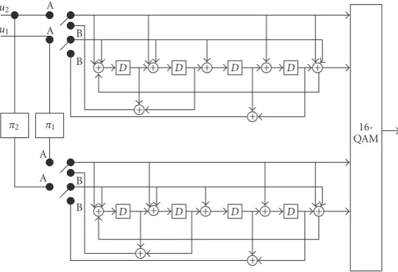
achieving a throughput ofb bps/Hz. One of the prototype of the 16-QAM TTCM is illustrated inFigure 2
A simple method can be used to describe the same code inFigure 3. This is equivalent to describing the turbo codes as a repeater (that is the simplest parity-check code), an in-terleaver, and one component code [14]. Two bit streams (u1
and u2) are provided at the input of the TCM encoder—
one is the original source information bit stream (u1), and
the other (u2) is the interleaved version corresponding to
the parity checks of the first one. TCM encoder has rate of 2/2, which combines only the original systematic bit (from
u1 stream) and the parity-check bit as the encoder
u2
u1 A
A B
B
D D D D
π2 π1
A
A B
B D D D D
16-QAM
+ + + + +
+
+
+ + + + +
+
+
Figure2: Parallel concatenated trellis-coded modulation,16-QAM.
u2
u1
vk+1 1
vk+1 0
vk 1
vk 0
D D D D
π
16-QAM
+ + + + +
Figure3: Parity-concantenated TCM encoder,16-QAM.
be half of the information block size, the function of this con-catenated structure is exactly the same as that of TTCM.
Figure 4illustrates the equivalence between TTCM and parity-concatenated TCM.Figure 4(a)is the 16-QAM block diagram of TTCM encoder with short block inputs u1 = u3
1u21u11u01 and u2 = u32u22u12u02, whereas u01 and u02 are the
LSBs andu31 andu32 are the MSBs. Assume after
interleav-ing, two input sequences to the second constituent encoder areu1
2u02u32u22andu21u01u11u31, then 4 coded output sequences
would beu3
1u21u11u01,v31v21v11v01,u12u02u32u22, and v23v22v21v20. The
similar coding results can be obtained through the encoder in Figure 4(b) with only a difference in the partial parity-check bits. The merge from encoder ofFigure 4(b)to that ofFigure 4(c)is straight forward when we set the interleaver size and pattern as shown inFigure 4(c).
Figure 5describes the simplified encoder for 64-QAM modulation. There are 4 information streams (u1,u2,u3, and u4) into the encoder. Among those four information streams,
two streams (u3 andu4) are the interleaved versions of the
original two source streams (u1andu2), respectively. Again,
two consecutive clock cycle outputs are mapped onto 64-QAM constellation via Gray mapping.
There are three advantages for such a modification. (a) We consider fewer interleavers: only one interleaver for the 16-QAM case (instead of 2) and 2 interleavers for 64-QAM
case (instead of 4). (b) We save one constituent encoder. (c) It is easy to extend this to parity-concatenated codes. That is, we simply replace the repeater with a parity-check code.
When this coding scheme is applied to the OFDM system over the UWB channel, the coded bit stream is interleaved prior to modulation in order to provide robustness against burst errors. The bit interleaving operation is performed in two stages: symbol interleaving followed by OFDM tone in-terleaving. The symbol interleaver permutes the bits across OFDM symbols to exploit frequency diversity across sub-bands, while the tone interleaver permutes the bits across the data tones within an OFDM symbol to exploit frequency di-versity across tones and provide robustness against narrow-band interference.
We constrain our symbol interleaver to a regular block interleaver ofsizeNP×numberof encoder output bits, where
NPis the input information packet length and the number of encoder output bits is 2 for 16-QAM and 4 for 64-QAM. The coded bits are read in columnwise and read out rowwise. The output of the symbol block interleaver is then passed through a tone block interleaver ofsizeNOFDM×tonenumbers in one
OFDM symbol, whereNOFDMis the OFDM symbol numbers
u2
Figure4: Expansion from Benedetto’s TTCM to parity-concatenated TCM.
u2
Figure5: Parity-concatented TCM encoder, 64-QAM.
3.2. Bit iterative MAP decoder
The MAP (maximum a posteriori probability) algorithm in iterative decoding calculates the logarithm of likelihood ratio (LLR),Λ(ub), associated with each decoded bitubat timek through (11) [20]:
probability(APP) of the data bitub. The APP of a decoded data bitub can be derived from the joint probabilityλik(m) defined by
λi
kSk=Prub=i,Sk|yk, (12)
whereSkrepresents the encoder state at timekandykis the received channel symbol. Thus, the APP of a decoded data bitubis equal to
a decoded bitubcan be written as
Λub=log
Finally the decoder can make a decision by comparingΛ(ub) to a threshold equal to zero:
ub=1 ifΛub>0,
ub=0 ifΛub<0. (15)
The joint probability λik(Sk) can be rewritten using Bayes rule:
in which we assume the information symbol sequence{uk}
is made up ofNindependent input symbolsukwithKinput bits (i.e.,ub,b=1,. . .,K) in eachukand take into account that events after timekare not influenced by observationsyk1
and symbolukif encoder stateSkis known. For easy compu-tation of the probabilityλik(Sk), probability functionsαk(Sk),
Thenλik(Sk) can be simplified as
λi k
Sk=αkSkβkSk. (18)
The probabilitiesαk(Sk) andβk(Sk) can be recursively calcu-lated from probabilityγi(yk,Sk−1,Sk) through
can be determined from transition prob-abilities of the encoder trellis and the channel, which is given by 1 or 0 depending on whether theith bit is associated with transition from Sk−1 toSk or not, andπ(· | ·) is the state
transition probability that uses the extrinsic information of informationuk.
Using LLR Λ(ub) definition (Figure 10) and relations amongλik,αk,βk, andγiwe obtain put and of another information called extrinsic information generated by the decoder.
Divsalar and Pollara [22] described an iterative decoding scheme forqparallel concatenated convolutional codes based on approximating the optimum bit decision rule by consid-ering the combination of interleaver and the trellis encoder as a block encoder. The scheme is based on solving a set of nonlinear equations given by (q=2 is used here to illustrate the concept [10,22]) encoder, whereL1jare the extrinsic information andyqare
the received observation vectors corresponding to the qth
trellis code. The final decision is then based onLb=L1b+L2b,
which passed through a hard limiter with zero threshold. The above set of nonlinear equations is derived from the optimum bit decision rule
Lb=log
using the following approximation:
Pu|y1≈N
The nonlinear equations in (23) can be solved by using an iterative procedure
The LLR of a symbolugiven the observationyis calculated first using the symbol MAP algorithm
λ(u)=logP
u|y
P0|y, (26)
where 0 corresponds to the all-zero symbol. The symbol MAP algorithm [21] can be used to calculate (26), as shown inFigure 6[10]. Then the LLR of thebth bit within the sym-bol can be obtained by
Lb=log
The symbol a priori probabilities needed in the symbol MAP algorithm, which is used in branch transition probability cal-culation, can be obtained by
P(u)=K b=1
eubLb
1 +eLb (28)
with the assumption that the extrinsic bit reliabilities coming from the other decoder are independent.
In our case, we apply the turbo iterative MAP decod-ing scheme in [10,20,21], and make certain modifications to fit our concatenated encoder structure. For example, we only need one bit MAP decoder instead of two as in [10] for iterative decoding, since the outer parity-check encoders can be viewed as repeaters. So, the corresponding outer de-coders only exchange extrinsic information between repeated bit streams. The decoder structure is depicted inFigure 7.
The bit MAP decoder computes thea posteriori probabil-itiesP(ub |y,u) (yis the received channel symbol anduis the result from previous iteration), or equivalently the log-likelihood ratioΛ(ub) = log(P(ub = 1 | y,u)/P(ub = 0 |
Delay
L(m)2 SymbolMAP1 λ
(u) Bit reliability calculation
L1b− L(m+1)1 +
y1
Delay
L(m)1
π2 Symbol MAP2
λ(u) Bit reliability calculation π
−1 2
L2b
L(m+1)2
+
−
y2
Decoded bits
Figure6: Iterative(trubo)decoder structure for two trellis codes.
L(ub)
e in Extrinsic information L(ueb)out updating
Bit MAP decoder
Extrinsic information extraction (ub)
Received signal and/or
channel information Output at
final iteration
Figure7: Block diagram of the iterative decoder.
fromLe(ub)out=Λ(ub)−Lc(ub)−Le(ub)into avoid
informa-tion being used repeatedly. It will be supplied to the parity-check decoder. The outer parity-parity-check decoder updates the
Le(ub)outintoLe(ub)inaccording to parity-check constraints
between information bits and supplies it to the bit MAP de-coder for the next iteration.Le(ub)inis the extrinsic
informa-tion, which is used as a priori probability for branch metric computation in MAP decoding process.Lc(ub) is the channel reliability for eachub.
Since half of the systematic bits from the inner TCM en-coder are punctured, it seems that we can only get chan-nel transition probability for the remaining half of the information bits and parity-check bits. However, the punc-tured information bits are the parity checks of those system-atic bits at the encoder outputs except they are interleaved. So we can always find the channel transition probability for the punctured information bits through the unpunctured part. The extrinsic information value associated withπ(·/·) in (20) is given as the logarithm format:
Leub=logP
ub=1
Pub=0. (29)
Ifq(ub=1/Sk−1,Sk)=1, then
πSk/Sk−1
= eLe(ub)
1 +eLe(ub), (30)
otherwise
πSk/Sk−1
= 1
1 +eLe(ub). (31)
4. DENSITY EVOLUTION FOR TTCM
Convergence analysis of iterative decoding algorithms is of-ten used to predict code performance and to provide insight into the encoder structure. One of the methods—extrinsic information transfer (EXIT) method—has been widely used in particular [23–25]. The EXIT chart is a tool for study-ing the convergence of turbo decoders without simulatstudy-ing the whole decoding process. We use the density evolution method in [24] to confirm our simulation.
an independent Gaussian variable. Thus, the dependence be-tween the extrinsic information bits is wiped out. This is the main difference between density evolution and simulation. Since TCM is typically irregular, density evolution using the all-zero sequence may be biased. So we need to consider both 0-bit and 1-bit as inputs which could bring a negative mean according to the definition of extrinsic information in (29). We examine the mean of extrinsic information using tens of thousands of randomly generated bit sequences and make it always positive regardless of bit sequences by weighting the sign of the bit. Such a mean can be easily traced by two de-coding trajectories in the density evolution chart, that is,
μLe=Le
ub2ub−1, (32)
where overbar denotes the average. For UWB channels, we then average it over more than 2000 UWB channels.
Procedure of density evolution can be summarized as fol-lows.
(1) Before the first iteration starts, all the extrinsic infor-mation is set to zero.
(2) We divide each decoding process into two halves— one half-iteration for TCM followed by another iteration for parity-check codes. For each half-iteration, we calculate the updated extrinsic informa-tion through decoding. Using tens of thousands of simulation, we get the mean of the densities of those updated extrinsic information using (32).
(3) Further, we assume the density to be Gaussian with the mean computed in (32) and the variance equal to twice the mean based on density symmetry condition [25]. Then, we regenerate the extrinsic information as an independent Gaussian variable for the next half-iteration.
(4) During each half-iteration, SNR is estimated as half of the mean of extrinsic information. SNR, before and af-ter each half-iaf-teration, can then be tracked in the den-sity evolution chart as in this paper.
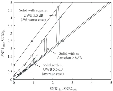
The EXIT chart (seeFigure 8)is plotted as a combina-tion of two charts, one is for SNR1in and SNR1out and the
second is for SNR2inand SNR2out. It shows input and
out-put of extrinsic information (in terms of signal-to-noise ra-tio) for each decoder. Since the extrinsic information out-put of the first decoder is fed as the inout-put for the second de-coder, the combination of two charts easily demonstrates the convergent property of the code. For example, if two input-output curves are crossing, then the iterative decoder stops at the crossing point, which corresponds to a fixed nonzero error rate. Otherwise, the decoder produces extrinsic infor-mation with unbounded SNR, which corresponds to a zero error rate. The threshold is defined as the minimum value of signal-to-noise ratio that will generate two curves without a crossing point. Density evolution can be used to determine the threshold, which is the minimum SNR for the decoder to converge assuming infinite block length. In the density evo-lution chart, as long as the SNR is above the threshold, these two constituent transfer curves will never intersect, which
0 0.5 1 1.5 2 2.5 3 3.5 4 4.5 5
SNR1
out
,S
N
R
2in
0 1 2 3 4 5
SNR1in, SNR2out Solid with square:
UWB 5.5 dB (2% worst case)
Solid with o: Gaussian 2.8 dB Solid with +:
UWB 5.5 dB (average case)
Figure8: Density evolution for UWB/OFDM/16-QAM on AWGN and UWB channels.
means convergence in the limiting case. A detailed descrip-tion of density evoludescrip-tion and EXIT chart can be found in [23,25].
InFigure 8, we show density evolution for OFDM sys-tems using 16-QAM on Gaussian and UWB fading channels. For Gaussian channels, we find the threshold is 2.6 dB and show the EXIT chart for Eb/N0 = 2.8 dB. On UWB
chan-nels, we find that if we take average over all 2000 chanchan-nels, then EXIT chart shows the clear case of convergence (see curves with solid squares in Figure 8). However, if we run EXIT over each individual channel instance, then some chan-nel instances require much larger SNRs to allow iterative de-coding to converge to the correct codewords. For example, at Eb/No = 5.5 dB, about 2% of the channels are harder to converge (see curves with crosses in Figure 8). We call them “bad” channels. WhenEb/Nois small, the percentage of the worst channels increases significantly. For example, when
Eb/No =4.5 dB, about 20% of channels are bad. Good per-formance can only be achieved if the interleaver can fully ran-domize the extrinsic information over all channels. If the bits of a packet are interleaved over a number of channels con-taining significant amount of “bad” channels, then the per-formance will be much worse. This is the main reason that the packet error rate curve for UWB cannot drop sharply as those on AWGN channels.
Figure 9 presents the density evolution analysis for OFDM system using 64-QAM on Gaussian and UWB fad-ing channels. For Gaussian channels, we find the threshold is 3.7 dB and show the EXIT chart forEb/No =4.2 dB. For UWB channels, when we setEb/No = 9.2 dB, about 2% of the channels are bad.
5. NUMERICAL RESULTS
0 0.5 1 1.5 2 2.5 3 3.5 4 4.5 5
SNR1
out
,S
N
R
2in
0 1 2 3 4 5
SNR1in, SNR2out Solid with square:
UWB 9.2 dB (2% worst case)
Solid with o: Gaussian 4.2 dB Solid with +: UWB 9.2 dB (average case)
Figure9: Density evolution for UWB/OFDM/64-QAM on AWGN and UWB channels.
Table1: COFDM system parameters.
Information data rate 640 Mbps / 1.2 Gbps
Constellation 16-QAM/64-QAM
16-state TCM code (23,35,27)/(23,35,33,37,31)
FFT size 128
Data tones 100
System bandwidth 528 MHz
Subcarrier frequency spacing 4.125 MHz
IFFT/FFT period 242.42 ns
Cyclic prefix duration 60.61 ns
Gaurd interval duration 9.47 ns
Symbol interval 312.5 ns
Time-domain spreading Yes
Multipath tolerance 60.6 ns
UWB channel model AR model
for performance comparison. A 16-state TCM code with octal notation (23,35,27) is chosen with 16-QAM modu-lation and (23,35,33,37,31) for 64-QAM modumodu-lation. The resultant data rates are 640 Mbps and 1.2 Gbps, respec-tively. System-level simulations were performed to estimate the bit error rate (BER) and packet error rate (PER) per-formance. Table 1 shows a list of key COFDM parame-ters used in our simulations. The system is assumed to be perfectly synchronized. All simulation results are averaged over 2000 packets with a payload of 1 KB for 640 Mbps system and 2 KB for 1.2 Gbps system. There are 2000 dif-ferent UWB channel realizations involved in the simula-tion.
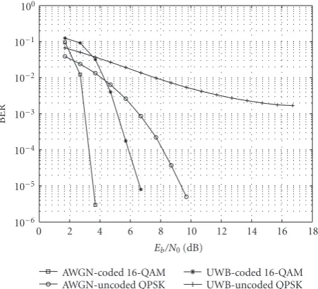
Figure 10shows the BER performance of the coded 16-QAM OFDM system and uncoded OFDM system in both UWB and AWGN channels as a function ofEb/N0. Uncoded
modulation scheme is QPSK in order to keep same system
10−6 10−5 10−4 10−3 10−2 10−1 100
BER
0 2 4 6 8 10 12 14 16 18
Eb/N0(dB) AWGN-coded 16-QAM AWGN-uncoded QPSK
UWB-coded 16-QAM UWB-uncoded QPSK
Figure10: BER of OFDM/16-QAM over UWB and AWGN chan-nel.
coding rate. For UWB channels, the line-of-sight (LOS) dis-tance between the transmitter and receiver is 10 m. To mea-sure BER at each point, we simulate up to 1.64×107bits,
which is 2000 packets ×41 OFDM symbols/packet ×100 QAM symbols/OFDM symbol ×2 bits/QAM symbol. The coded OFDM curve shows a big performance improvement over uncoded OFDM, especially on UWB channels. Further-more, a BER of 8×10⁻⁶ is obtained at Eb/N
0 = 6.7 dB. Figure 11 describes the PER performance of the 640 Mbps coded OFDM system and uncoded case over UWB and AWGN channels. The low PER of 0.036 is obtained at
Eb/N0 = 6.7 dB for coded OFDM over 10 m UWB
chan-nels.
The BER performance for 64-QAM coded OFDM sys-tem and 16-QAM uncoded OFDM syssys-tem is illustrated in Figure 12. Again uncoded modulation scheme is lower than coded modulation scheme to keep the same sys-tem coding rate. There are 3.28×10⁷ (2000 packets ×41
OFDM symbols/packet ×100 QAM symbols/OFDM sym-bol×4 bits/QAM symbol) random bits simulated to mea-sure the BER. The LOS of the UWB channel distance is 10 m. The simulation results indicate a BER of 2.3×10⁻⁵
atEb/N0 =10.7 dB for 1.2 Gbps coded OFDM system over
UWB channels. Figure 13 presents the PER performance for the same situation, reporting a low PER of 0.011 at
Eb/N0=10.7 dB for 1.2 Gbps coded OFDM over UWB
chan-nels.
6. CONCLUSION
10−2 10−1 100
PE
R
0 2 4 6 8 10 12 14 16 18
Eb/N0(dB) AWGN-coded 16-QAM AWGN-uncoded QPSK
UWB-coded 16-QAM UWB-uncoded QPSK
Figure11: PER of OFDM/16-QAM over UWB and AWGN channel.
10−6 10−5 10−4 10−3 10−2 10−1 100
BER
2 4 6 8 10 12 14 16 18
Eb/N0(dB) AWGN-coded 64-QAM AWGN-uncoded 16-QAM
UWB-coded 64-QAM UWB-uncoded 16-QAM
Figure12: BER of OFDM/64-QAM over UWB and AWGN chan-nel.
interleavers. The scheme can be applied to the OFDM sys-tem over UWB channels for higher spectral efficiency. We identify several essential requirements to achieve high rate such as frequency and time diversity, and multilevel error protection. The simulation results show that we can deliver data rates from 640 Mbps up to 1.2 Gbps to current UWB systems. The results are confirmed by density evolution. In the future, we will extend the TTCM to parity concatenated TCM (i.e., replacing repeater to single parity-check code) for rate change, and perform a more accurate analysis on its BER upper bound and possible error floor.
10−2 10−1 100
PE
R
2 4 6 8 10 12 14 16 18
Eb/N0(dB) AWGN-coded 64-QAM AWGN-uncoded 16-QAM
UWB-coded 64-QAM UWB-uncoded 16-QAM
Figure13: PER of OFDM/64-QAM over UWB and AWGN channel.
ACKNOWLEDGMENTS
This project was supported in part by the National Aero-nautics and Space Administration through the University of Central Florida’s Florida Space Grant Consortium. Part of this work was presented at ISIT 2005, Adelaide, Australia, September 2005.
REFERENCES
[1] M. Z. Win and R. A. Scholtz, “Characterization of ultra-wide bandwidth wireless indoor channels: a communication-theoretic view,”IEEE Journal on Selected Areas in Communica-tions, vol. 20, no. 9, pp. 1613–1627, 2002.
[2] A. F. Molisch, J. R. Foerster, and M. Pendergrass, “Channel models for ultrawideband personal area networks,”IEEE Wire-less Communications, vol. 10, no. 6, pp. 14–21, 2003.
[3] W. Turin, R. Jana, S. S. Ghassemzadeh, C. W. Rice, and T. Tarokh, “Autoregressive modeling of an indoor UWB chan-nel,” inProceedings of IEEE Conference on Ultra Wideband Sys-tems and Technologies, pp. 71–74, Baltimore, Md, USA, May 2002.
[4] L. J. Cimini Jr., “Analysis and simulation of a digital mobile channel using orthogonal frequency division multiplexing,”
IEEE Transactions on Communications, vol. 33, no. 7, pp. 665– 675, 1985.
[5] A. Batra, et al., “Multi-band OFDM physical layer proposal for IEEE P802.15 task group 3a,” IEEE P802.15-03/268r2, Novem-ber 2003.
[6] B. L. Floch, M. Alard, and C. Berrou, “Coded orthogonal fre-quency division multiplex,”Proceedings of the IEEE, vol. 83, no. 6, pp. 982–996, 1995.
[7] G. Ungerboeck, “Channel coding with multilevel/phase sig-nalling,” IEEE Transactions on Information Theory, vol. 28, no. 1, pp. 55–67, 1982.
International Conference on Communications (ICC ’94), vol. 2, pp. 645–649, New Orleans, La, USA, May 1994.
[9] P. Robertson and T. W¨orz, “Bandwidth-efficient turbo trellis-coded modulation using punctured component codes,”IEEE Journal on Selected Areas in Communications, vol. 16, no. 2, pp. 206–218, 1998.
[10] S. Benedetto, D. Divsalar, G. Montorsi, and F. Pollara, “Parallel concatenated trellis coded modulation,” inProceedings of IEEE International Conference on Communications (ICC ’96), vol. 2, pp. 974–978, Dallas, Tex, USA, June 1996.
[11] G. D. Forney Jr., M. D. Trott, and S.-Y. Chung, “Sphere-bound-achieving coset codes and multilevel coset codes,”IEEE Transactions on Information Theory, vol. 46, no. 3, pp. 820– 850, 2000.
[12] Q. Wang, L. Wei, and R. A. Kennedy, “Iterative Viterbi de-coding, trellis shaping, and multilevel structure for high-rate parity-concatenated TCM,”IEEE Transactions on Communica-tions, vol. 50, no. 1, pp. 48–55, 2002.
[13] Q. Wang and L. Wei, “Graph-based iterative decoding algo-rithms for parity-concatenated trellis codes,”IEEE Transac-tions on Information Theory, vol. 47, no. 3, pp. 1062–1074, 2001.
[14] D. Divsalar, H. Jin, and R. J. McEliece, “Coding theorems for turbo-like codes,” inProceedings of 36th Allerton Conference Communication, Control and Computing, pp. 201–210, Mon-ticello, Ill, USA, September 1998.
[15] A. Batra, J. Balakrishnan, G. R. Aiello, J. R. Foerster, and A. Dabak, “Design of a multiband OFDM system for realistic UWB channel environments,”IEEE Transactions on Microwave Theory and Techniques, vol. 52, no. 9, pp. 2123–2138, 2004. [16] M. Z. Win and R. A. Scholtz, “Impulse radio: how it works,”
IEEE Communications Letters, vol. 2, no. 2, pp. 36–38, 1998. [17] A. Saleh and R. Valenzuela, “A statistical model for indoor
multipath propagation,” IEEE Journal on Selected Areas in Communications, vol. 5, no. 2, pp. 128–137, 1987.
[18] B. Muquet, Z. Wang, G. B. Giannakis, M. de Courville, and P. Duhamel, “Cyclic prefixing or zero padding for wireless multi-carrier transmissions?”IEEE Transactions on Communications, vol. 50, no. 12, pp. 2136–2148, 2002.
[19] A. Scaglione, G. B. Giannakis, and S. Barbarossa, “Redundant filterbank precoders and equalizers —part I: unification and optimal designs and part II: blind channel estimation, syn-chronization, and direct equalization,”IEEE Transactions on Signal Processing, vol. 47, no. 7, pp. 1988–2022, 1999. [20] C. Berrou, A. Glavieux, and P. Thitimajshima, “Near shannon
limit error-correcting coding and encoding: turbo-codes 1,” in
Proceedings of IEEE International Conference on Communica-tions (ICC ’93), vol. 2, pp. 1064–1070, Geneva, Switzerland, May 1993.
[21] L. R. Bahl, J. Cocke, F. Jelinek, and J. Raviv, “Optimal decod-ing of linear codes for minimizdecod-ing symbol error rate,”IEEE Transactions on Information Theory, vol. 20, no. 2, pp. 284– 287, 1974.
[22] D. Divsalar and F. Pollara, “On the design of turbo codes,” JPL TDA Progress Report 42-123, Jet Propulsion Laboratory, Pasadena, Calif, USA, November 1995.
[23] S. ten Brink, “Convergence behavior of iteratively decoded parallel concatenated codes,”IEEE Transactions on Communi-cations, vol. 49, no. 10, pp. 1727–1737, 2001.
[24] D. Divsalar, S. Dolinar, and F. Pollara, “Serial turbo trel-lis coded modulation with rate-1 inner code,” in Proceed-ings of IEEE International Symposium on Information Theory (ISIT ’00), p. 194, Sorrento, Italy, June 2000.
[25] D. Divsalar, S. Dolinar, and F. Pollara, “Iterative turbo decoder analysis based on density evolution,”IEEE Journal on Selected Areas in Communications, vol. 19, no. 5, pp. 891–907, 2001.
Yanxia Wangreceived the B.S. and M.S. de-grees in electrical engineering from Wuhan Technical University of S&M, China, in 1993 and 1996, respectively, and an M.S. degree in electrical engineering from the School of Electrical Engineering and Com-puter Science, University of Central Florida, Orlando, USA, in 2001. She is now a Ph.D. candidate at the same university. From 1996 to 1999, she held a research and
teach-ing position in Information Department of North China Elec-tric Power University. Her general interests lie in the area of cod-ing/decoding algorithm design and signal processing for wireless communications systems. Most recent research is in the area of turbo TCM coding/decoding, OFDM systems over ultra-wideband channel, and power-line channels.
Libo Yangreceived the B.E. and M.E. de-grees in electrical engineering, in 2000 and 2003, respectively, from Nanjing University of Posts and Telecommunications, China. He is currently working towards the Ph.D. degree in the School of Electrical Engineer-ing and Computer Science at the Univer-sity of Central Florida, Orlando, FLa, USA. His research interests are in the area of wire-less communications and signal processing,
currently working on error control codes design and analysis, and its application in ultra-wideband communications.
Lei Weireceived the M.E. degree from the University of New South Wales, Sydney, Australia, in 1993, and the Ph.D. degree from the University of South Australia, Ade-laide, Australia, in 1995, both in electrical engineering. From 1995 to 2000, he was a faculty member with the Department of En-gineering, Australian National University, Canberra, Australia. During 2000–2001, he was with the Telecommunications