The drawings and specifications contained herein shall not be reproduced in whole or in part without written pennission.
IBM has prepared this maintenance manual for the use of IBM Customer Engineers in the installation, maintenance and repair of the specific machines indicated. IBM makes no representations that it is suitable for any other purpose.
Infonnation contained in this manual is subject to change from time to time. Any such change will be reported in subsequent revisions or distributed through Customer Engineering Memorandums (CEMs) to all subscribers.
Requests for copies of IBM publications should be made to your IBM representative or to the IBM Branch Office servicing your locality.
Comments about the publications may be addressed to (IBM Corporation, 740 New Circle Road N.W., Publications Department 901, Lexington, Ky. 40511). IBM may use or distribute any of the infonnation you supply in any way it believes appropriate without incurring any obligation what-ever. You may, of course, continue to use the infonnation you supply.
"It is possible that this material may contain reference to, or information about, IBM products (machines and programs), programming, or services that are not announced in your country. Such references or infonnation must not be construed to mean that IBM intends to announce such IBM products,programming, or services in your country." "IBM," "Executive," "IBM EXECUTARY," and "Selectric" are registered trademarks of the IBM Corporation.
©Copyright International Business Machines Corporation 1980, 1981 1982
SAFETY PRECAUTIONS
All IBM Customer Engineers are expected to take every safety precaution possible and observe the following
safety practices when servicing IBM equipment. .
Mechanical Safety:
1. Safety glasses must be worn.
2. All safety devices, such as guards, shields, signs, ground wires, etc., must be restored after main-tenance. When a guard or shield is removed to observe or make an adjustment, that shield must be replaced when work in the area is completed. 3. Watches, rings, necklaces, ID bracelets, etc" must be removed when servicing the machine. 4. Care must be used when working near moving parts. Keep hair away from moving parts. A void wearing loose clothing that might be caught in the machine. Shirt sleeves must be kept but-toned or rolled above the elbows. Ties must be tucked in the shirt or have a tie clasp approxi-mately three inches from the end. Tie chains are not recommended.
Electrical Safety:
1. The eqUipment referenced in this manual may use high voltages. Check voltage labels! 2. Safety glasses must be worn when checking
energized circuits.
3. If a circuit is disconnected for servicing or parts replacement, it must be reconnected and tested before allowing the use of the machine. 4. Power should be removed from the machine for
servicing whenever possible. Remember, when checking voltages, avoid contacting ground potential, such as metal floor strips, machine frame, etc.
5. Meter continuity checks should be used instead of voltage checks whenever possible.
6. Do not apply power to any part, component, or subassembly when it is not physically mounted in the machine, or its approved ser-vice position.
General Safety:
1. Each Customer Engineer is responsible to be certain no action on his/her part makes the product unsafe or exposes customer personnel to hazards.
2. Store the removed machine covers in a safe, out of the way place where no one can trip over them.
3. If you must leave the machine in a down condi-tion, always install the covers and disconnect the power before leaving the customer's office. 4. Always place CE tool kit away from walk areas
where no one can trip over it.
5. Maintain safe conditions in the area of the machine while performing and after completing maintenance.
6. Before starting the equipment, make sure fellow CEs and customer personnel are not in a hazard-ous position.
IBM DISPLAYWRITER MAP 0001-1
MAP REFERENCE TABLE
PAGE 1 OF 2
+---+
+---+
1 MAP NO·1 TITLE 1 MAP NO.1 TITLE
1---1
1 0001 TABLE OF CONTENTS 7010 COMMUNICATIONS
1 0002 INTRODUCTION 7020 INTERNAL EIA CABLE
1 0009 START-OF-CALL MAP 7030 INTERNAL COMMUNICATIONS CABLE
1 0010 SYSTEM ENTRY MAP 7060 PORT 4 NO VOLTAGE
1 0015 ERROR LED STATUS MAP 7061 P4AjP4B NO VOLTAGE
1 0017 LED STATUS MAP 7062 FEATURE CARD POWER
0019 ERROR CODE (03,06,08,09) MAP 8020 RNA START MAP
1010 KEYBOARD ENTRY MAP 8021 READ ID ERROR MAP
1011 SPEAKER CHECK MAP 8022 DISKETTE DRIVE NOT READY MAP
1012 DISTRIBUTION CABLE MAP 8025 UNSAFE WRITE CONDITION MAP
1013 KEYLOCK ON FAILURE 8026 NO INDEX PULSES MAP
1014 KEYLOCK OFF FAILURE 8028 SEEK ERROR MAP
4011 CABLE DETECTION REPAIR- CONN. 0 8030 NOT WRITING/WRITE ERRORS MAP 4012 RECEIVE CIRCUIT REPAIR- CONN. 0 8032 H/S WRAP AND/OR CABLE WRAP ERRORS 4013 TRANSMIT CIRCUIT REPAIR- CONN. 0 8060 DISKETTE UNIT +5 VDC POWER MAP 4211 SHARING INTERRUPT REPAIR 8061 DISKETTE UNIT +24 VDC POWER MAP 4212 SHARING INTERRUPT REPAIR 8062 DISKETTE UNIT -5 VDC POWER MAP 4213 CABLE DETECTION REPAIR- CONN. 6A 8064 DISKETTE UNIT A/C POWER FAILURE 4214 RECEIVE CIRCUIT REPAIR- CONN. 6A 8065 DC SHORT FAILURE MAP
4215 TRANSMIT CIRCUIT REPAIR- CONN. 6A 9010 BLANK DISPLAY MAP 4216 CABLE DETECTION REPAIR- CONN. 6B 9020 DISPLAY ADAPTER MAP 4217 RECEIVE CIRCUIT REPAIR- CONN. 6B 9030 NO VIDEO DATA MAP
4218 TRANSMIT CIRCUIT REPAIR- CONN. 6B 9040 DISTORTED DISPLAY IMAGE MAP 5011 CABLE DETECTION REPAIR- CONN. 0 9050 NO CONTRAST ADJUSTMENT MAP 5012 RECEIVE CIRCUIT REPAIR- CONN. 0 9109 LARGE DISPLAY INDICATOR MAP 5013 TRANSMIT CIRCUIT REPAIR-CONN. 0 9110 LARGE DISPLAY ENTRY MAP
5030 FREQUENCY DRIFT ON PRINTER COMMO. 9112 LARGE DISPLAY DISTORTED SHAPE MAP
6010 POWER SUPPLY MAP 9115 LARGE DISPLAY IMAGE QUALITY MAP
+---+
+---+
IBM DISPLAYWRITER MAP 0001-2 MAP REFERENCE TABLE
PAGE 2 OF 2
+---+
1 MAP NO.1 TITLE 1
1---1
1 9165 1 LARGE DISPLAY AC POWER MAP 1
1
1
APPENDIX A - DISPLAY IMAGE FIGURES 1 1 1 APPENDIX B - DISPLAY IMAGE FIGURES 1 1 1 APPENDIX C - CUSTOMER PRINT 11 1 APPENDIX D - GLOSSARY 1
+---+
IBM Displaywriter INTRODUCTION PAGE 1 OF 4
MAP S (MAINTENANCE ANALYSIS PROCEDURES) 1. THESE MAPS ARE USED FOR TWO REASONS.
a. They aid in diagnosing System failures. b. They aid in learning Diagnostic Procedures. 2. STEPS FOR USING MAPS.
a. You should have received a Service Request Number when notified of the Call. The Service Request Number is used to determine which FRU to bring.
b. Make a quick visual check for problems (loose or broken parts, loose connectors, etc.) A visual check may be quicker than a MAP diagnosis.
c. You should begin in the Start-of-Call MAP. The Start-of-Call MAP will send you to an area MAP, determined by your Service Request Number or to the System Entry MAP if you do not have a Service Request Number.
d. These MAPs aid in finding problems. An instruction or question can be read wrong. If the problem is not solved, you should start again in the MAPs and read each step very carefully. If you go through the MAPs a second time and you still have not solved the problem, i t may be because the machine has two problems or an intermittent problem. The EC levels of the MAPs may not be correct. Verify the EC Level of the MAPs. If this does not solve the problem and you cannot repair it, follow your normal escalation procedure.
MAP 0002-1
IBM Displaywriter INTRODUCTION PAGE 2 OF 4
e. ESCALATION PROCEDURE
When i t is necessary to follow your normal escalation procedure, you should be prepared in the following way:
1) The type of jobs or functions that fail should be listed. 2) You should know the sequence leading to the failure.
3) You should have the History Card available with all o~tions, EC levels and CEMs listed.
3. BASIC MAP INFORMATION:
a. A MAP aids you in finding a problem by using questions concerning the System sym~toms. Each question is written so i t can be answered YES or NO. When you answer "YES" or "NO" to a question, the MAP will lead you to a fix, a question, or another MAP.
b. At the start of each MAP, an Entry and Exit Table specifies the locations in the MAPs of any Entry or Exit Points.
DIAGNOSTIC PROCEDURES
INTRODUCTION: VOLTAGE, GROUND AND CONTINUITY READINGS
The following text describes some SAFETY Procedures. It has information on voltage, ground and continuity readings. Unless you understand these MAPs, read the information below before you go to the Start-of-Call MAP.
IBM Displaywriter INTRODUCTION PAGE 3 OF 4
CAUTION
ALWAYS POWER-OFF WHEN CHECKING THE PRIMARY POWER FUSE, DISCONNECTING OR CONNECTING ANY ELECTRICAL PART, UNLESS OTHERWISE DIRECTED. IT IS A GOOD IDEA TO REMOVE POWER WHEN CHECKING ANY FUSE.
4. VOLTAGE READINGS
a. Every time a voltage reading is requested in these MAPs, the readings are to be taken with the CE Meter (PN 9900628). If a different meter is used in a World Trade Country, that Country must check the readings with their meter and make a conversion table if necessary. All AC voltages must be accurate to plus or minus 10% (WT: plus 8%, minus 12%).
b. All DC voltages must be accurate to plus or minus 10%. Unless stated otherwise, all connectors should be connected normally when a voltage reading is taken.
c. The AC line voltage on U.S. machines should be between 104 (ac) volts and 127 (ac) volts. On GBG/I machines, the voltage will differ by Country.
5. GROUND CHECKS
a. To check a ground point, measure between the ground point and a known voltage source. The reading must equal the voltage on that source if the ground is good. Continuity readings may be used to check grounds, but measure to a known ground point. Use the lowest ohm scale and check for less than two (2.0) ohms.
CAUTION
ALWAYS REMOVE POWER BEFORE TAKING A CONTINUITY READING.
MAP 0002-3
IBM Displaywriter INTRODUCTION PAGE 4 OF 4
6. CONTINUITY READINGS
a. When taking continuity readings, back circuits can affect the reading. If necessary, disconnect connectors. An open circuit will read over range (A one with no decimal point or zeros). A circuit with good continuity will read less than two (2.0) ohms. CARD/CABLE REPLACEMENT PROCEDURES
7. VOLTAGE READINGS
a. Voltage readings should be made at the suspected failing Electronics Card, if the normal map procedures were not successful. The voltage readings must be within the limits, as , stated in the Product Support Manual.
8. CARD/CABLE RESEATING
a. Reseat the suspected failing Electronics Card before replacing it.
b. Reseat the suspected failing cable before replacing it.
MAP 0002-4
START-OF-CALL MAP
MAP 0009
PAGE 1 OF 7
ENTRY POINTS
FROM
I
ENTER THIS MAP---+---MAP
I
ENTRY PAGE STEP NUMBERI
POINT NUMBER NUMBER---+---No entries in this table
001
(ENTRY POINT A)
Do you have a Service Request Number?
Y N
002
Do you area of YN
I I 003
I I Is the I Y N I
I
II
I II
I II
II
I
I I
I
II
3A B C D
suspect any specific failing?
Operator available?
EXIT POINTS
EXIT THIS MAP
I
TO---+---PAGE STEP
I
MAP ENTRY NUMBER NUMBERI
NUMBER POINT---+---1 004 0010 A
2 012 0010 A
7 020 0010 A
7 024 0010 A
SERVICE suspected Card or installing
NOTE: Reinsert the failing Electronic Cable, prior to a new part.
BCD MAP 0009-1
I
I
I
I
I
004
You are now directed to go to the System Entry MAP.
GO TO MAP 0010, ENTRY POINT A.
05
06
Instruct the Operator to use the Problem Determination Package (Problem
Determination Guide and Problem Determination
Diskette) to generate a Service Request Number.
Locate the Service Request Number in the Service Request Number Table and go to the MAP indicated or execute the MDI indicated.
Is the (loose cables,
Y N
problem easy to identify? key tops , knobs, covers, etc. )
I I
I I
I I
3 2
F 1
I
I
I
I
007START-OF-CALL MAP MAP 0009
PAGE 2 OF 7
Do you suspect a problem?
Paper Handling Y N
I
I
008I
I
Do you suspect the Printer? Y NI
I
009I
I
Do you suspect the Mag Card? I Y NI
I
I
I
I
I
I
I
I
I
I I
I I
I I
I I
I I
I I
I I
I I
I I
II
3 I
G H 010
Do you suspect Communications problem? Y N
011
a
Do you Resource Y N
suspect a Shared problem?
I
I 012
I
II
I
I
I
I LYou are now directed to go to the System Entry (Step 012 continues)
K L
I
I
I
I
I
(Step 012 continued)I
MAP.I
I
I
GO TO MAP 0010,I
ENTRY POINT A.I
I
13I
I
Load the DISPLAYWRITER SYSTEMI
DIAGNOSTICS.I
I
Select MDI s.I
I
Select Shared Resource ID "f"I
or "g".I
I
Run Shared Resource Tests.I
014
Make sure all the cables from the Media Module are attached. POWER-ON the System.
Load the DISPLAYWRITER SYSTEM COMMUNICATIONS DIAGNOSTICS. Select the Communications ID
"j ".
Run Communications Tests.
H J MAP 0009-2
I
I
I
I
I
015 16Make sure the Mag Card Cable is attached.
POWER-ON the System. POWER-ON the Mag Card.
Load the DISPLAYWRITER SYSTEM MAG CARD UNIT DIAGNOSTICS. Select MDIs.
Select Mag Card ID "i". Run Mag Card Tests.
Make sure the Printer Cable is attached.
POWER-ON the System. POWER-ON the Printer.
Load the DISPLAYWRITER SYSTEM DIAGNOSTICS.
Select MDIs. (Step 016 continues)
A E G
1 1 2
START-OF-CALL MAP MAP 0009
I
I
PAGE 3 OF 7I
I
(Step 016 continued)I
Select Printer ID "e".I
I
Run Printer Tests.I
017
Load the DISPLAYWRITER SYSTEM DIAGNOSTICS.
Select MDls.
I
I
Select Paper Handling IDI
"h".
I
I
Run Paper Handling Tests.I
018
Repair or Replace parts as necessary.
GO TO MAP 0010, ENTRY POINT A, to Verify System Operation. 19
Service
I
System Area RequestI
or Device NumberI
I
MAP No.I
orI
MOl ID---+---+---000001 I Memory 000001
I
Keyboard ID 000001I
Mag Card (Step 019 continues)c NOTE *
i
(Step 019 Service
I
Request
I
Number
I
continued) System Area
or Device
I
I
MAP No. orI
MOl ID---+---+---000001 Communications 000001 Printer 000001 Shared Printer 000001 000001 000001 000002 000800 000800 000801 000801 000801 000801 000801 000801 (Secondary) Shared Printer
(Primary) Sheet Feed Tractor Feed Call operator for specific information. LED A,B or C
"ON" LED D,E,F,G or
H "ON" Post-CRT Code
"01" Post-CRT Code
"02" Post-CRT Code
"03"
Poat-CRT Code "04" Post-CRT Code
"0511
Post-CRT Code
"0611
(Step 019 continues)
e g f h h N/A 6010 0015 1010 1010 0019 8032 8032 0019
(Step 019 Service
I
Request
I
Number
I
continued) System Area
or Device
MAP 0009-3
I
MAP No.I
orI
MOl ID---+---+---000801 Post-CRT Code 0019 000801 000900 000900 000900 000900 000900 000900 000900 000900 000900 000900 000900 021000 021001 021002 050002 050100 051025 052002 052007 052008 "08" Post-CRT Code
"09" *900* FFFO *900* FFFI *900* FFF2 *900* FFF3 *900* FFF4 *900* FFFA *900* FFFB *900* FFFF *900* Other *903*
*90B* Memory Memory Memory Printer Link Printer Printer Printwheel Printer Printwheel Printer Printwheel Printer (Step 019 continues)
0019 0010 0010 0010 0010 0010 0010 0010 0010 N/A N/A d c c c e e e e e e
START-OF-CALL MAP MAP 0009-4 MAP 0009
PAGE 4 OF 7
(Step 019 continued) (Step 019 continued) (Step 019 continued)
Service' System Area
,
MAP No. Service' System AreaI
MAP No. Service' System Area,
MAP No. RequestI
or DeviceI
or Request, or DeviceI
or Request, or Device,
orNumber
I
,
0001 ID Number,
,
0001 ID Number,
,
0001 ID---+---+---
---+---+---
---+---+---052010 Printwheel e 130005
,
Mag Card i 180025 Diskette dPrinter 130006
,
Mag Card i 181015 Diskette d052011 Printwheel e 131001
,
Mag Card i 190001 Display 9020Printer 1310.02
I
Mag Card i 190002 Display 9040052012 Printwheel e 131021
,
Mag Card i 190004 Display 9020Printer 131022
,
Mag Card i 190005 Display a052013 Printwheel e 131023
,
Mag Card i 191001 Display aPrinter 140002
,
Printer g 191002 Display 0010052014 Printwhee1 e
,
Sharing 191003 Display 0010Printer 140004
, Printer
g 191005 Display a052015 Printwhee1 e
,
Sharing 210007 Keyboard NOTE*
Printer 142001
,
Printer f 210010 Keyboard 0010052025 Printer e
,
Sharing 220008 Memory c052026 Printer e 150001
,
Printer Link e 220009 Memory c090000 Display 0010 150004
,
Printer Link e 220010 Memory 0010091004 Display 0010 151017
,
5215 Printer e 231004 Mag Card i110001 Keyboard NOTE
*
151018,
5215 Printer e 231006 Mag Card i110004 Keyboard NOTE
*
151024I
5215 Printer e 240001 See SR# 540001110013 Keyboard NOTE
*
152016,
Printer e 251008 5215 Printer e110014 Keyboard NOTE
*
152021, Printer
e 251019 5215 Printer e120001 System 0010 153006
I
Printer e 251021 5215 Printer e120004 Memory c 160001
, Power Supply
0010 252001 Printwheel e120005 Memory c 170701
, Communications
j Printer120006 Memory c 170721
,
Communications j 252017 Printer e120007 Memory c 170722
, Communications
j 252019 Printer e120011 System c 170723
,
Communications j 252020 Printer e120012 System c 180001
,
Diskette d 252022 Printer e130001
,
Mag Card i 180015I
Diskette d 252024, Printer
e(Step 019 continues) (Step 019 continues) (Step 019 continues)
START-OF-CALL MAP MAP 0009-5 MAP 0009
PAGE 5 OF 7
(Step 019 continued) (Step 019 continued) (Step 019 continued)
Service
I
System AreaI
MAP No. ServiceI
System AreaI
MAP No. ServiceI
System AreaI
MAP No. RequestI
or DeviceI
or RequestI
or DeviceI
or RequestI
or DeviceI
orNumber
I
I
MDl ID NumberI
I
MDl ID NumberI
I
MDl ID---+---+---
---+---+---
---+---+---253005
I
Printer e 321034 Memory c 352003 Printwheel e253007
I
Printer e 321035 Memory c Printer254002
I
Printer e 331003 Mag Card i 352004 Printwheel e254003
I
Printer e 331007 Mag Card i Printer270701
I
Communications j 331011 Mag Card i 352005 Printwheel e270702
I
Communications j 331016 Mag Card i Printer270743
I
Communications j 332101 Mag Card i 352018 Printer e270764
I
Communications j 332103 Mag Card i 352023 Printer e270775
I
Communications j 332202 Mag Card i 354001 Tractor Feed e270786
I
Communications j 332203 Mag Card i 370753 Communications j270807
I
Communications j 332301 Mag Card i 380004 Diskette d280005
I
Diskette d 332302 Mag Card i 380006 Diskette d281037
I
Diskette d 332303 Mag Card i 380007 Diskette d290003
I
Display 0010 332401 Mag Card i 380026 Diskette d310008
I
Keyboard NOTE*
332402 Mag Card i 380033 Diskette d310009
I
Keyboard NOTE*
332403 Mag Card i 380037 Diskette d310012
I
Keyboard NOTE*
332503 Mag Card i 381004 Diskette d310015
I
Keyboard NOTE*
332603 Mag Card i 381006 Diskette 8020321011
I
Memory c 332703 Mag Card i 381026 Diskette d321012
I
Memory c 332803 Mag Card i 381027 Diskette d321021
I
Memory c 332903 Mag Card i 381028 Diskette d321022
I
Memory c 342002 Printer f 381031 Diskette d321023
I
Memory c Sharing 381033 Diskette d321024
I
Memory c 342003 Printer f 430002 Mag Card i321025
I
Memory c Sharing 430007 Mag Card i321031
I
Memory c 342004 Printer f 431005 Mag Card i321032
I
Memory c Sharing 431012 Mag Card i321033
I
Memory c 431013I
Mag Card i(Step 019 continues) (Step 019 continues) (Step 019 continues)
START-OF-CALL MAP MAP 0009-6 MAP 0009
PAGE 6 OF 7
(Step 019 continued) (Step 019 continued) (Step 019 continued)
Service
I
System Area MAP No. ServiceI
System AreaI
MAP No. ServiceI
System AreaI
MAP No. RequestI
or Device or RequestI
or DeviceI
or RequestI
or DeviceI
orNumber
I
MOl ID NumberI
I
MOl ID NumberI
I
MOl ID--~----+---+---
---+---+---
---+---+---431014 Mag Card i 540001 Printer g 780035 Diskette 8020
431018 Mag Card i Sharing 781018 Diskette 8020
431020 Mag Card i 540003 Printer g 781035 Diskette 8020
432001 Mag Card i Sharing 832200 Mag Card i
432002 Mag Card i 553001 Sheet Feed e 880013 Diskette 8020
432004 Mag Card i Paper Handler 880036 Diskette 8020
432501 Mag Card i 553002 Sheet Feed e 881013 Diskette 8020
432601 Mag Card i Paper Handler 881036 Diskette 8020
432701 Mag Card i 580010 Diskette d 888888 Customer made
432801 Mag Card i 581010 Diskette d PDG error
432901 Mag Card i 581011 Diskette d 900004 Multiple Fault 0010
453003 Sheet Feed e 630004 Mag Card i 931009 Mag Card i
Paper Handler 632201 Mag Card i 932100 Mag Card i
453004 Sheet Feed e 652009 Printwhee1 e 932500 Mag Card i
Paper Handler Printer 932600 Mag Card i
480008 Diskette d 680011 Diskette d 932700 Mag Card i
480009 Diskette d 680017 Diskette 8020 932800 Mag Card i
480016 Diskette d 681017 Diskette 8020 932900 Mag Card i
480024 Diskette d 730003 Mag Card i 951001 5215 Printer e
480034 Diskette d 731015 Mag Card i 951020 5215 Printer e
481008 Diskette d 731017 Mag Card i 951022 5215 Printer e
481009 Diskette d 731019 Mag Card i 951023 5215 Printer e
481016 Diskette d 732300 Mag Card i 953008 Printer e
481034 Diskette d 732400 Mag Card i 980014 Diskette d
531008 Mag Card i 752006 Printwhee1 e 980019 Diskette 8020
531010 Mag Card i Printer 981019 Diskette 8020
532003 Mag Card i 777777 Communications j
---532102 Mag Card i 780018 Diskette 8020
(Step 019 continues) (Step 019 continues) (Step 019 continues)
START-OF-CALL ~ffiP
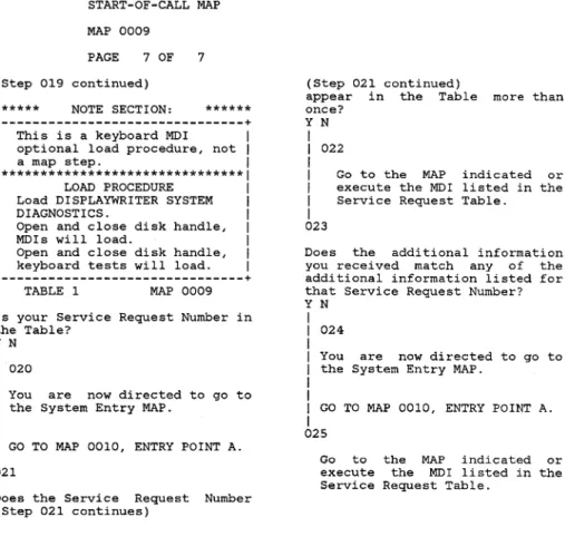
MAP 0009 PAGE 7 OF 7 (Step 019 continued)
******
NOTE SECTION:******
+---+
This is a keyboard MDI
I
optional load procedure, not
I
I a map step. I
1*******************************1
I LOAD PROCEDURE I
I
Load DISPLAYWRITER SYSTEMI
I
DIAGNOSTICS.I
I Open and close disk handle, I
I MDls will load. I
I
Open and close disk handle,I
I keyboard tests will load. I
+---+
TABLE 1 MAP 0009 Is your Service Request Number in the Table?
Y N
I
I
020I
I
You are now directed to go toI
the System Entry MAP.I
I
I
GO TO MAP 0010, ENTRY POINT A.I
021
Does the Service Request Number (Step 021 continues)
(Step 021 continued) appear in the Table
once?
Y N
I
I
022I
more than
I
I
I
Go to the MAP indicated or execute the MDI listed in the Service Request Table.
I
023
Does the additional information you received match any of the additional information listed for that Service Request Number? Y N
I
I
024I
I
You are now directed to go to I the System Entry MAP.I
I
I
GO TO MAP 0010, ENTRY POINT A.I
025
Go to the MAP indicated or execute the MDI listed in the Service Request Table.
MAP 0009-7
SYSTEM ENTRY MAP MAP 0010
PAGE 1 OF 7 ENTRY POINTS
FROM
I
ENTER THIS MAP---+---MAP
I
ENTRY PAGE STEP NUMBERI
POINT NUMBER NUMBER---+---ALL MAPS RETURN TO MAP 0010
001
(ENTRY POINT A) POWER-OFF.
Remove any Diskette that may be in the Drive.
(Step 001 continues)
EXIT POINTS
EXIT THIS MAP
I
TO---+---PAGE STEP
I
MAP ENTRY NUMBER NUMBERI
NUMBER POINT---+---4 028 0015 A
4 023 0017 A
4 024 0017 A
4 027 0017 A
4 029 6010 A
6 043 8020 A
6 044 8020 A
7 050 8020 A
3 015 8064 A
6 039 9020 A
4 022 9030 A
5 033 9040 A
5 034 9109 A
6 040 9109 A
4 018 9165 A
MAP 0010-1
(Step 001 continued)
Is
POWER-ON.
Wait 20 seconds for BAT to complete.
Turn the Display Brightness and Contrast Control Knobs fully clockwise.
the IBM LOGO visible on the Display?
Y N I I I I I
002
Is an Error Code displayed at the bottom of the screen?
Y N 003
Check the LED Indicators. Are there any LED Indicators ON? (A,B,C,D,E,F,G,H)
Y N
I
I 004
I
I
I
I
I
Check to see if the Fan in the Electronic Module (Step 004 continues) 5 4
SYSTEM ENTRY MAP MAP 0010
PAGE 2 OF 7
(Step 004 continued) is running. Is the Module YN
Fan in
running? the Electronic
1
1
005 11
11
1
1
1
1
1
It appears not present Supply. POWER-OFF.
that AC Power is at the Power
Remove the Primary Power Fuse from Panel 2.
Using the lowest ohms range, check the continuity (less than 2 ohms) of the Fuse. Is the Power Supply Fuse bad? YN
1 1 006
1 DANGER
1
1 HIGH VOLTAGE IS PRESENT AT 1 THE POWER CORD CONNECTOR. 1
1
1 Disconnect the Power Cord 1 (Step 006 continues)
1 4 3 DE
(Step 006 continued) Connector (9) at Panel 2. Power Cord Connector (9) configuration.
/ L
/
1
1 G
1 1
1 N
1
1 _ _ _ _
Using the 200(ac) voltage range, measure the voltage at Power Cord Connector (9).
+---+
1 Connector 1 (ac)
1 Pins 1 Voltage Range 1
1---+---1
1 L to G 1 104 to 127 volts 1 1 L to N 1 104 to 127 volts 1
+---+
(WT-GBG/I refer to Chart in the Product (Step 006 continues)
Voltage Support
MAP 0010-2
(Step 006 continued) Manual.)
Is the voltage in the correct voltage range?
Y N
F 007
Disconnect the Power Cord Connector from the wall outlet.
Using the 200(ac) voltage range, measure the voltage at the outlet.
Is the voltage in the correct voltage range?
Y N 1 1 008
1
1 Inform the Customer.
1 009
Install a new Power Cord. GO TO MAP 0010, ENTRY POINT A, to Verify SystemOp,eration.
E 2
F SYSTEM ENTRY MAP 2
MAP 0010
I
I
PAGE 3 OF 7I
I
010
POWER-OFF. Install
Supply. a new base Power GO TO MAP 0010, ENTRY POINT A, to Verify System Operation. 11
Install a new Fuse. POWER-ON.
Is the Fan in the Electronic Module running?
Y N
4 012
Is there a Large Display Module connected to the Electronic Module?
Y N
I
I
013I
I
POWER-OFF.I
I
Disconnect the DisketteI
(Step 013 continues)I
G H
(Step 013 continued)
Unit AC(output) Cable Connector (8) at Panel 2.
Install a new Fuse. POWER-ON.
Is the Fan in the Electronic Module running?
Y N
I
I
014I
I
I
I
I
I
POWER-OFF. Install Supply.
a new base Power
I
GO TO MAP 0010, ENTRY POINT A, I to Verify System Operation.I
015
The Problem is in the Diskette Area.
You are now directed to go to the Diskette Unit AIC Power Failure MAP.
GO TO MAP 8064, ENTRY POINT A.
H
I
I
I
I
I
016
POWER-OFF.
MAP 0010-3
Disconnect the Large Display Module Cable Connector (12) at the Electronic Module, Panel 2. Install a new fuse.
POWER-ON.
Is the Fan in the Electronic Module running?
Y N
I
I
017I
I
I
I
I
I
POWER-OFF. Install Supply.
a new base Power
I
GO TO MAP 0010, ENTRY POINT A,I
to Verify System Operation.I
018
You are now directed to go to the Large Display AC Power MAP. (Step 018 continues)
D G 2 3
SYSTEM ENTRY MAP MAP 0010
I I
I I
PAGE 4 OF 7I I
I I
(Step 018 continued)I I
GO TO MAP 9165,I I
ENTRY POINT A.I I
I
019I
I
GO TO MAP 0010, ENTRY POINT A,I
to Verify System Operation.I
020
Is the Display Screen blank? (no illumination) Y N
totally
I
I
021I
I
I
I
I
I
I
I
I
I
I
I
I
I
I
I
I
I
I
Is there a Large Display Module connected to the Electronic Module?
Y N
I
I 022
I
I
I
I
I
I
You are now directed to go to the Display No Video Data MAP.
I
GO TO MAP 9030,I
ENTRY POINT A.I
I
I
I
J K
C J K 1
I I
I I
I I
I I
I I
I
023I
I
You are now directed to go toI
the LED Status MAP.I
I
I
GO TO MAP 0017,I
ENTRY POINT A.I
024
You are now directed to go to the LED Status MAP.
GO TO MAP 0017, ENTRY POINT A. 25
Are any of the A, B or C LED Indicators ON?
Y N
L 026
POWER-OFF.
Position the Electronic Module so the LED Indicators may be easily observed. While observing the LED (Step 026 continues)
L MAP 0010-4
(Step 026 continued) Indicators, POWER-ON.
At the start, did all the LED Indicators light?
Y N
I
I
027I
I
You are now directed to go toI
the LED Status MAP.I
I
I
GO TO MAP 0017,I
ENTRY POINT A.I
028
You are now directed to go to the Error LED Status MAP. GO TO MAP 0015, ENTRY POINT A. 29
You are now directed to go to the Power Supply MAP.
GO TO MAP 6010; ENTRY POINT A.
A B SYSTEM ENTRY MAP 1 1
MAP 0010 I
I PAGE 5 OF 7
I I 030
Select the Error Code in the following Chart and go to the indicated MAP.
Post-CRT Error Code Table Error LED MAP Entry Code Code Number Point
DEFGH
+---+
01 00110 1010 A
02 00110 1010 A 03 00111 0019 A 04 01000 8032 A 05 01000 8032 A 06 01001 0019 A 08 01010 0019 A 09 01100 0019 A
+---+
31
Adjust the Brightness Control to obtain a correct visual level.
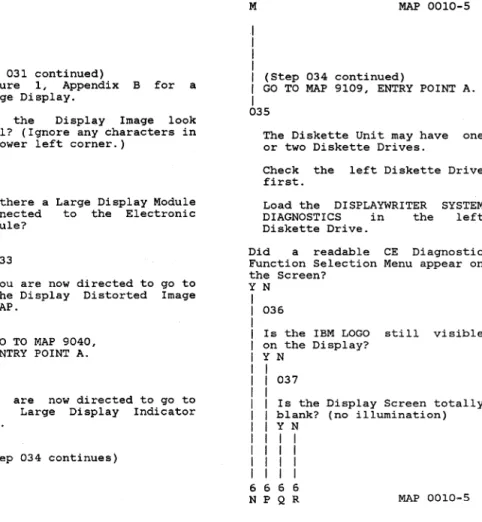
Compare the Display Image to the Picture of a normal Display in Figure 1, Appendix A or (Step 031 continues)
(Step 031 continued)
Figure 1, Appendix B for a large Display.
Does the Display Image look normal? (Ignore any characters in the lower left corner.)
Y N
M 032
Is there a Large Display Module connected to the Electronic Module?
YN 033
You are now directed to go to the Display Distorted Image MAP.
GO TO MAP 9040, ENTRY POINT A. 34
You are now directed to go to the Large Display Indicator MAP.
(Step 034 continues)
M
I
I
I
I
MAP 0010-5
I
(Step 034 continued)I
GO TO MAP 9109, ENTRY POINT A.I
035
The Diskette Unit may have one or two Diskette Drives.
Check the left Diskette Drive first.
Load the DISPLAYWRITER SYSTEM DIAGNOSTICS in the left Diskette Drive.
Did a readable CE Diagnostic Function Selection Menu appear on the Screen?
YN 036
Is the IBM LOGO still visible on the Display?
Y N I I 037 I
I Is the Display Screen totallY I blank? (no illumination) I Y N
I I I I I I I I I I I I 6 6 6 6
Q 5
R SYSTEM ENTRY MAP 5
MAP 0010
I
I
PAGE 6 OF 7I
I
038
Is there a Large Display Module connected to the Electronic Module?
Y N
I
I
039I
I
You are now directed to go toI
the Display Display AdapterI
MAP.I
t
I GO TO MAP 9020,
I
ENTRY POINT A.I
040
You are now directed to go to the Large Display Indicator MAP.
GO TO MAP 9109, ENTRY POINT A. 41
POWER-OFF. POWER-ON.
(Step 041 continues)
P 5
(Step 041 continued)
Load a known good Diskette. Is the Display Screen totally blank? (no illumination)
YN
I
I
042I
I
Obtain a new DISPLAYWRITERI
SYSTEM DIAGNOSTIC diskette.I
I
GO TO MAP 0010, ENTRY POINTI
A, to Verify SystemI
Operation.I
043
You are now directed to go to the RNA Start MAP.
GO TO MAP 8020, ENTRY POINT A. 044
The Problem is in the Diskette Area.
You are now directed to go to the RNA Start MAP.
(Step 044 continues)
N 5
I
I
I
MAP 0010-6
I
(Step 044 continued)I
GO TO MAP 8020, ENTRY POINT A.I
045
Can you select the MDI function and load it?
YN 046
47
Turn the Diskette Load Lever to the left, then to the right.
The DISPLAYWRITER SYSTEM DIAGNOSTICS Procedures (MDls) will load.
Repeat the above procedure and the Keyboard Diagnostic procedures (MDls) will load. Follow the instructions on the Display.
The System may Diskette Drives, right.
have left two and Does the System have a right
(Step 047 continues)
SYSTEM ENTRY MAP MAP 0010
PAGE 7 OF 7 (Step 047 continued) Diskette Drive? Y N
048
49
Run all MOl unit required for configuration.
tests your If no unit tests failed, run the System Exerciser.
If no trouble is you think the working correctly, to the customer.
found, and System is return i t If you think there is
problem, go to Intermittent Problem Diagnostic Approach in the Product Manual.
still a the section Support
Select Diskette ID "d". Run Diskette Tests.
Remove the DISPLAYWRITER SYSTEM DIAGNOSTICS from the left (Step 049 continues)
(Step 049 continued) Diskette Drive.
POWER-OFF, then POWER-ON the System.
Load the DISPLAYWRITER SYSTEM DIAGNOSTICS in the right Diskette Drive.
Did a readable CE Diagnostic Function Selection Menu appear on the Screen?
YN 050
The Problem is in Diskette Area.
You are now directed to go the RNA Start MAP.
the to
GO TO MAP 8020, ENTRY POINT A. 051
Select MOls.
Run all MOl unit tests required for your configuration.
(Step 051 continues)
MAP 0010-7
(Step 051 continued)
If no unit tests failed, run the System Exerciser.
If no trouble is found, think the System is correctly, return i t
customer.
and you working to the If you think there is still a problem, go to the Intermittent Problem Diagnostic Approach section in the Product Support Manual.
ERROR LED STATUS MAP
MAP 0015
PAGE 1 OF 11
ENTRY POINTS
FROM
I
ENTER THIS MAP---+---MAP
I
ENTRY PAGE STEP NUMBERI
POINT NUMBER NUMBER---+---0009 0010
001
A A
(ENTRY POINT A) 1 1
001 001
This MAP locates the failing part when an error occurs during the POWER-ON sequence.
The Error LED Indicators are marked by (D,E,F,G,H).
Where: O=OFF, l=ON
***
NOTE***
When the "0" indicator is on, the other indicators are meaningless.
The question below has two parts. If you can answer EITHER part yes, answer the (Step 001 continues)
EXIT POINTS
EXIT THIS MAP
I
TO---+---PAGE STEP
I
MAP ENTRY NUMBER NUMBERI
NUMBER POINT---+---3 016
I
9109 A(Step 001 continued) question yes.
MAP 0015-1
Is the
"0"
indicator "ON"or
do the Error Indicators (D,E,F,G,H) equal (0,1,1,1,1)? YN
002
Do the Error Indicators (D,E,F,G,H) equal (0,0,0,0,1)? Y N
I
I
003I
I
Do the Error IndicatorsI
(D,E,F,G,H) equalI
(0,0,0,1,0)?I
Y NI I
I I
004I I
I I
Do the Error IndicatorsI I
(D,E,F,G,H) equalI I
(0,0,0,1,1)?I I
Y NI I I I
I I I I
I I I I
1
I I I I
0 9 7 6 2E 1
I
I
I
I
005
ERROR LED STATUS MAP
MAP 0015
PAGE 2 OF 11
Do the Error Indicators (D,E,F,G,H) equal (0,1,1,1,0)?
Y N
006
Do the Error Indicators (D,E,F,G,H) equal (0,0,1,0,0)?
Y N
5 4
007
Do the Error Indicators (D,E,F,G,H) equal
(0,0,1,0,1)?
Y N
008
Select the Displayed Error Code or if i t is not readable, select the LED Error Code in the following Chart and go to the indicated MAP.
(Step 008 continues)
F G H
H
(Step 008 continued)
Post-CRT Error Code Table
---Error LED MAP Entry Code Code Number Point
DEFGH
+---+
01 00110 1010 A 02 00110 1010 A 03 00111 0019 A 04 01000 8032 A OS 01000 8032 A 06 01001 0019 A 08 01010 0019 A 09 01100 0019 A
+---+
09
POWER-OFF.
Disconnect the Display Module Connector (2).
POWER-ON.
Wait about 10 seconds, then check the Error Indicators. (Step 009 continues)
MAP 0015-2
(Step 009 continued)
Did the BAT fail with Indicators (D,E,F,G,H) (0,0,1,0,1)?
Error equal
Y N
010
Is there a Large Display Module connected to the Electronic Module?
Y N
011
Using the 20(dc) voltage range, measure from Pin 2 (ground) to Pin 7 (+5V) of the Internal Distribution Cable Connector (2) (pin side) .
Is the between volts?
voltage reading +4.6 volts and +5.5
Y N
I
I
012I
I
I
I
I
I
Using the 20(dc) voltage range, measure from frame ground to Pin 8 of the (Step 012 continues)
333
L 2
I
I
I
I
I
I
I
I
I
I
I
I
I
I
I
I
I
II
I
I
I
I
I
I
I
I
I
I
ERROR LED STATUS MAP
MAP 0015
PAGE 3 OF 11 (Step 012 continued)
Internal Distribution Connector (P2). Cable Is the voltage reading between +4.6 volts and +5.5 volts? Y N
I
I
013I
I
I
I
I
II
I
I
POWER-OFF. Install a Supply.new base Power GO TO MAP 0010, ENTRY POINT A, to Verify System Operation.
I
014POWER-OFF.
Install a new
Distribution Cable. Internal
I
GO TO MAP 0010, ENTRY POINT A,I
to Verify System Operation.I
015POWER-OFF.
(Step 015 continues)
J K
2 2
(Step 015 continued) Install a new Module.
GO TO MAP 0010, ENTRY A, to Verify Operation. 16 POWER-OFF. Display POINT System
Reconnect the Display Module Cable Connector (2).
You are now directed to go to the Large Display Indicator MAP.
GO TO MAP 9109, ENTRY POINT A.
17
Has a new Display Adapter Card been installed?
Y N
I
I
018I
I
POWER-OFF.I
I
Install a new Display AdapterI
(SteP 018 continues)I
I
M
M MAP 0015-3
(Step 018 continued) Card.
Reconnect the Display Module Cable Connector (2).
GO TO MAP 0010, ENTRY POINT A, to Verify System Operation. 19
Do you have Cards plugged in slot "A" or "C" of the Electronic Module Distribution Board? Y N
020
POWER-OFF.
Reinstall the original Display Adapter Card.
Install a new System Card. Reconnect the Display Module Cable Connector (2).
GO TO MAP 0010, ENTRY POINT A, to Verify System Operation. 21
(Step 021 continues)
ERROR LED STATUS MAP MAP 0015
PAGE 4 OF 11 (Step 021 continued)
POWER-OFF.
Reinstall the original Display Adapter Card.
Reconnect the Display Module Cable Connector (2).
Remove the Card(s) from slot(s) "A" and/or "C".
POWER-ON. Do the
(D,E,F,G,H) YN
Error Indicators equal (0,0,1,0,1)?
I
I
022I
I
I
I
I
I
I
I
I
I
I
I
I
I
I
I
I
N POWER-OFF. Reinstall Cards. POWER-ON.one of the removed
If the Error Indicators (D,E,F,G,H) = (0,0,1,0,1), the Card just reinstalled is defective. If not, repeat this procedure until the failing Card is identified. (Step 022 continues)
G N
(Step 022 continued)
Exchange the failing Card. GO TO
MAP
0010, ENTRY POINT A, to Verify System Operation.23
POWER-OFF.
Install a new System Card.
I
I
Reinstall Card(s) in slot(s)I
"A" and/or "C".I
I
GO TO MAP 0010, ENTRY POINT A,I
to Verify System Operation.I
024
Has a new Display Adapter Card been installed?
YN
I
I
025I
I
:POWER-OFF.I
I
lnstall a new Display AdapterI
Carel.I
I
(Step 025 continues)I
I
P PI
I
I
I
MAP 0015-4
I
(Step 025 continued)I
GO TO MAP 0010, ENTRY POINT A,I
to Verify System Operation.I
026
Do you have Cards plugged in slot "A" or
"e"
of the Electronic MOdule Distribution Board?Y N
I
I
027I
I
I
I
I
I
I
I
I
POWER-OFF.Install a new Electronic Module Distribution Soard. Reinstall the original Display Adapter Card.
I
GO TO MAP 0010, ENTRY POINT A,I
to Verify System Operation.I
028
POWER-OFF.
Remove the Carcl(s) from slot(s) "A" and/or "C".
POWER-ON.
(Step 028 continues)
ERROR LED STATUS MAP MAP 0015
PAGE 5 OF 11 continued) (Step 028
Do the (D,E,F,G,H) YN
Error Indicators equal (0,0,1,0,0)? 029
POWER-OFF.
Reinstall one of the removed Cards.
POWER-ON.
If the Error Indicators (D,E,F,G,H)
=
(0,0,1,0,0), the Card just reinstalled is defective. If not, repeat this procedure until the failing Card is identified. Exchange the failing Card. GO TO MAP 0010, ENTRY POINT A, to Verify System Operation. 30POWER-OFF.
Install a new Electronic Module Distribution Board.
(Step 030 continues)
F 2
I
I
I
I
(Step 030 continued)I
GO TO MAP 0010, ENTRY POINT A,I
to Verify System Operation.I
031
Has a New Memory Card been installed in slot "E"?
Y N 032
POWER-OFF.
Install a new Memory Card in slot "E".
GO TO MAP 0010, ENTRY POINT A, to Verify System Operation. 33
Has a new System Card been installed?
Y N 034
POWER-OFF.
Install a new System Card. GO TO MAP 0010, ENTRY POINT A, (Step 034 continues)
Q MAP 0015-5
I
I
I
I
I
(Step 034 continued)I
to Verify System Operation.I
035
POWER-OFF.
Remove the Display Adapter Card and any card or cards in slot( s) "A",
"c"
and "F".POWER-ON.
Do the Error Indicators (D,E,F,G,H) equal (0,1,1,1,0)? YN
R 036
POWER-OFF.
Reinstall one of the removed Cards.
POWER-ON.
If the Error Indicators (D,E,F,G,H)
=
(0,1,1,1,0), the Card just reinstalled is defective. If '. not, repeat this procedure' until the' failing Card is identified." (Step 036 continues)R 5
I
ERROR LED STATUS MAP MAP 0015
I
PAGE 6 OF 11I
I
(Step 036 continued)I
Exchange the failing Card.I
I
GO TO MAP 0010, ENTRY POINT A,I
to Verify System Operation.I
037
Do you have a Memory Card in slot "F"?
Y N 038
POWER-OFF.
Install a new Electronic Module Distribution Board. Reinstall all the original cards.
Reconnect connectors.
all the cable GO TO MAP 0010, ENTRY POINT A, to Verify System Operation. 39
POWER-OFF.
Remove the Memory Card in slot
"F".
(Step 039 continues)
(Step 039 continued) POWER-ON.
Do the Error Indicators (D,E,F,G,H) equal (0,1,1,1,0)? Y N
I
I
040I
I
POWER-OFF.I
I
Install a new Memory Card inI
slot "F".I
I
GO TO MAP 0010, ENTRY POINT A,I
to Verify System Operation.I
041
POWER-OFF.
Install a new Electronic Module Distribution Board.
Reinstall cards. Reconnect connectors.
all all
the original the cable GO TO MAP 0010, ENTRY POINT A, to (Step 041 continues)
D 1
I
I
I
MAP 0015-6
I (Step 041 continued)
I
Verify System Operation.I
042
Has a new System Card been installed?
Y N
I
I
043I
I
POWER-OFF.I
I
Install a new System Card.I
I
GO TO MAP 0010, ENTRY POINT A,I
to Verify System Operation.I
044
POWER-OFF.
Remove all cards from the Electronic Module Distribution Board except the Display Adapter Card.
Reinstall the original System Card.
POWER-ON.
Do the Error Indicators (Step 044 continues)
ERROR LED STATUS MAP MAP 0015
PAGE 7 OF 11 (Step 044 continued)
(D,E,F,G,H) equal (0,0,0,1,1)? Y N
045
POWER-OFF.
Reinstall one of the removed Cards.
POWER-ON.
If the Error Indicators (D,E,F,G,H)
=
(0,0,0,1,1), the Card just reinstalled is defective. If not, repeat this procedure until the failing Card is identified. Exchange the failing Card. GO TO MAP 0010, ENTRY POINT A, to Verify System Operation. 46POWER-OFF.
Remove the Display Adapter Card and install the Memory Card in slot "E".
(Step 046 continues)
(Step 046 continued) POWER-ON.
Do the Error Indicators (D,E,F,G,H) equal (0,0,0,1,1)? Y N
I
I
047I
I
POWER-OFF.I
I
Install a new Display AdapterI
Card.I
I GO TO MAP 0010, ENTRY POINT A,
I
to Verify System Operation.I
048
POWER-OFF.
Install a new Electronic Module Distribution Board.
Reinstall all cards.
Reconnect connectors.
a11
the original the cable GO TO MAP 0010, ENTRY POINT A, to Verify System Operation.
C 1
I
I
I
I
049
MAP 0015-7
Has a New Memory Card been installed in slot "E"?
Y N
I
I
050I
I
POWER-OFF.I
I
Install a new Memory Card inI
slot "E".I
I GO TO MAP 0010, ENTRY POINT A,
I
to Verify System Operation.I
051
Using the 20(dc) voltage range, measure from frame ground to the pins in the following Chart.
+---+
I
Conn.I
PinI
Voltage RangeI
1---1
I
El 11 +4.6 to +5.5I
I
El 13 -4.6 to -5.5I
I
E1 15 +8.245 to +8.9251I
E1 20 +11.04 to +13.20I
+---
CHART CONTINUES---+
(Step 051 continues)
ERROR LED STATUS MAP MAP 0015
PAGE 8 OF 11 (Step 051 continued)
+---
CHART CONTINUED---+
1 Conn. 1 Pin 1 Voltage Range 11---1
1 E2 11 +4.6 to +5.5 1
1
E2 13 -4.6 to -5.51
1 E2 15 +8.245 to +8.9251 1 E2 20 +11.04 to +13.20 11---1
1 E3 11 +4.6 to +5.5 1
1---1
1 E4 11 +4.6 to +5.51
+---+
Were all the voltage measurements correct?
Y N
9 S
052
POWER-OFF. Test Conditions:
a. Position the Electronic Module Distribution Board to permit access for making voltage
measurements on Connector (AI) .
b. All cables are to be (Step 052 continues)
(Step 052 continued) connected.
c. All cards are to be in place.
POWER-ON.
Using the 20(dc) voltage range, measure from each pin in the following Chart to frame ground at the Power Supply Case.
+---+
1 Pin Voltage Range 1
1---1
3 -0.1 to +0.1 1 4 -0.1 to +0.1 1 5 -0.1 to +0.1 1 6 -0.1 to +0.1 1 8 -11.04 to -13.20 1 9 +4.6 to +5.5 1 10 +4.6 to +5.5 1 11 +4.6 to +5.5 1 12 +4.6 to +5.5 1 13 -4.6 to -5.5 1 15 +8.245 to +8.9251 16 -0.1 to +0.1 1 17 -0.1 to +0.1 1 18 -0.1 to +0.1 1 20 +11.04 to +13.20 1+--- CHART CONTINUES ---+
(Step 052 continues)
MAP 0015-8
(Step 052 continued)
+---
CHART CONTINUED---+
1 Pin Voltage Range 11---1
1 21 +4.6 to +5.5 1 1 22 +4.6 to +5.5 1 1 23 +4.6 to +5.5 1 1 24 +4.6 to +5.5 1
+---+
Were all the voltage measurements correct?
Y N 1 1 053 1
1 POWER-OFF. 1
1 Disconnect System Power Cable Connectors PI and Al.
9 T
Using the lowest ohms range, check the continuity of each wire in the System Power Cable.
Refer to the Product Support Manual for pin assignments. (Step 053 continues)
T 8
ERROR LED STATUS MAP MAP 0015
PAGE 9 OF 11 (Step 053 continued)
Was the cable continuity correct? (less than 2 ohms) Y N
I
I
054I
I Install a new System Power
I
Cable.I
I
GO TO MAP 0010, ENTRY POINTI
A, to Verify SystemI
Operation.I
055 Install
Supply. a new base Power GO TO MAP 0010, ENTRY POINT A, to Verify System Operation. 56
POWER-OFF.
Install a new Electronic Module Distribution Board.
Reinstall all
cards. the
original
(Step 056 continues)
S 8
I
I
I
I
(Step 056 continued)I
Reconnect all the cableI
connectors.I
I
GO TO MAP 0010, ENTRY POINT A,I
to Verify System Operation.I
057
Do you have a Memory Card in slot
"F"?
Y N
I
I
058I
I
POWER-OFF.I
I
Install a new System Card.I
I
GO TO MAP 0010, ENTRY POINT A,I
to Verify System Operation.I
059
Has a new System Card been installed?
Y N
I
I
060I
I
POWER-OFF.I
I
Install a new System Card.I
(Step 060 continues)I
I
U
B U 1
MAP 0015-9
I
I
I
I
I
(Step 060 continued)I
I
GO TO MAP 0010, ENTRY POINTI
A, to Verify SystemI
Operation.I
061
POWER-OFF.
Install a new Memory Card in slot "F".
Reinstall all the original cards.
Reconnect all
connectors. the cable GO TO MAP 0010, ENTRY POINT A, to Verify System Operation. 062
Has a New Memory Card been installed in slot "E"?
Y N
I
I
063I
I
POWER-OFF.I
I
Install a new Memory Card inI
(Step 063 continues) I1
o
V
9
ERROR LED STATUS MAP MAP 0015
I
I
PAGE 10 OF 11I
I
(Step 063 continued)I
slot "E".I
I
GO TO MAP 0010, ENTRY POINT A,I
to Verify System Operation.I
064
Has a new System Card been installed?
Y N
I
I
065I
I
POWER-OFF. II
Install a new System Card.I
I
GO TO MAP 0010, ENTRY POINT A,I
to Verify System Operation.I
066
POWER-OFF.
Install a new Electronic Module Distribution Board.
Reinstall cards. Reconnect connectors.
all all (Step 066 continues)
the original the cable
A
::.
I
I
I
I
(Step 066 continued)I
I
GO TO MAP 0010, ENTRY P01Nt A,I
to Verify System Operation.I
067
Has a new System Card been installed?
Y N
I
I
068I
I
POWER-OFF.I
I Install a new System Card.
I
I
GO TO MAP 0010, ENTRY POINT A,I
to Verify System Operation.I
069
POWER-OFF. Test Conditions:
a. Position the Electronic Module Distribution Board to permit access for making voltage measurements on Connector (Al).
b. All cables are
(Step 069 continues) to be
MAP 0015-10
(Step 069 continued) connected.
c. All cards are to be in place.
POWER-ON.
Using the 20(dc) voltage range, measure from each pin in the following Chart to frame ground at the Power Supply Case.
+---+
Pin Voltage Range 3 -0.1 to +0.1 4 -0.1 to +0.1 5 -0.1 to +0.1 6 -0.1 to +0.1 8 -11.04 to -13.20 9 +4.6 to +5.5 10 +4.6 to +5.5 11 +4.6 to +5.5 12 +4.6 to +5.5 13 -4.6 to -5.5 1S +8.245 to +8.925 16 -0.1 to +0.1 17 -0.1 to +0.1 18 -0.1 to +0.1 20 +11.04 to +13.20 +--- CHART CONTINUES ---+ (Step 069 continues)
ERROR LED STATUS MAP MAP 0015
PAGE 11 OF 11 (Step 069 continued)
+---
CHART CONTINUED---+
1 Pin Voltage Range 11---1
1 21 +4.6 to +5.5 1
1 22 +4.6 to +5.5 1 1 23 +4.6 to +5.5 1
1 24 +4.6 to +5.5 1
+---+
Were all the voltage measurements correct?
YN
W 070
POWER-OFF.
Disconnect System Power Cable Connectors Pl and Al.
Using the lowest ohms range, check the continuity of each wire in the System Power Cable.
Refer to the Product Support Manual for pin assignments. (Step 070 continues)
W
1
1
(Step 070 continued)
Was the cable continuity correct? (less than 2 ohms) Y N
1
1 071 1
1 Install a new System Power
1 Cable.
1
1 GO TO MAP 0010, ENTRY POINT 1 A, to Verify System 1 Operation.
1
072 Install Supply.
a new base Power
1 GO TO MAP 0010, ENTRY POINT
1 to Verify System Operation. 1
A,
073
POWER-OFF.
Install a new Electronic Module Distribution Board.
Reinstall all cards.
the (Step 073 continues)
original
MAP 0015-11
(Step 073 continued)
Reconnect all the cable connectors.
GO TO MAP 0010, ENTRY POINT A, to Verify System Operation.
LED Sl'ATUS MAP
MAP 0017
PAGE 1 OF 4
ENTRY POINTS
FROM 1 ENTER THIS MAP
---+---MAP 1 ENTRY PAGE STEP NUMBER 1 POINT NUMBER NUMBER
---+---0010 A 1 001
001
(ENTRY POINT A)
POWER-OFF.
Position the Electronic Module so the LED Indicators may be easily observed.
While observing the LED Indicators, POWER-ON.
At the start, did all the LED Indicators light?
Y N 1 1 1 1
I 1
1 1
1 1
1 11 1
I 1
3 1 A BE:XIT POINTS
EXIT THIS MAP 1 TO
---+---PAGE STEP 1 MAP ENTRY NUMBER NUMBER 1 NUMBER POINT
---~---+---4 4
019 1 9010 020 1 9109
A A
B
1 1 1 1 1
002
MAP 0017-1
Did "A" I "B"
Y N
or
"c"
fail to light?1
1 003
1
1
1
1
1
1 1 1
Using the 20(dc) voltage range, measure from frame ground to Pin 8 of the LED Assembly Cable Connector (S2) for +4.6 volts to +5.5 volts.
Is the voltage reading between +4.6 volts and +5.5 volts?
Y N
004
Using the 20(dc) voltage range, measure from frame ground to the Pins in the following Chart.
+--SYSTEM POWER CABLE (Al)--+ 1 Pin Voltage Range 1
1---1
1 9 +4.6 to +5.5 1
1 10 +4.6 to +5.5 1 1 11 +4.6 to +5.5 1
I---(CHART CONTINUES)---I
(Step 004 continues)
3 2
LED STATUS MAP MAP 0017 PAGE 2 OF 4 (Step 004 continued) I---(CHART
1 12
CONTINUED)---I +4.6 to +5.5 1 +4.6 to +5.5 1 +4.6 to +5.5 1 +4.6 to +5.5 1 1 22
1 23
1 24
+---+
Is the voltage reading between +4.6 volts and +5.5 volts? Y N
005
POWER-OFF.
Using the lowest ohms range, measure the continuity of each wire in the System Power Cable (PI to AI).
Refer to the Product Support Manual for pin assignments. Was the cable continuity correct? (less than 2 ohms) Y N
1 1 006 1
1 1
1
1 1
I
F
Install a new System Cable.
(Step 006 continues)
Power
D E F 1 1 1 1
1 (Step 006 continued)
1
1 GO TO MAP 0010, ENTRY POINT
1 A, to Verify System 1 Operation.
1
007
Install a new base Power Supply.
GO TO MAP 0010, ENTRY POINT A, to Verify System Operation.
08
POWER-OFF.
Install a new System Card. GO TO MAP 0010, ENTRY POINT A, to Verify System Operation. 09
POWER-OFF.
Use a CE Meter lead for a jumper.
CAUTION (Step 009 continues)
MAP 0017-2
(Step 009 continued)
Do NOT ground Pin 8. It is +5 volts.
Connect each Pin of LED Assembly Cable Connector (S2) in the Chart to frame ground. POWER-ON.
Verify that the respective LED Indicator lights.
+---+
1 Pin LED 1
1---·---1
1 2 D 1
1 3 E 1
1 5 F 1
1 6 G 1
1
7
H1
+---+
Did each LED Indicator light? Y N
1 1 010 1 1 1 1 1 1
POWER-OFF.
Install a' new LED Indicator Assembly.
1 (Step 010 continues) 1
3
C G 1 2
LED STATUS MAP MAP 0017
I
I
PAGE 3 OF 4I
I
(Step 010 continued)I
GO TO MAP 0010, ENTRY POINTI
A, to Verify SystemI
Operation.I
011POWER-OFF.
Install a new System Card. GO TO MAP 0010, ENTRY POINT A, to Verify System Operation. 12
Using the 20(dc) voltage range, measure from :frame ground to Pin 5 of the LED Assembly Cable Connector (Ll) (still connected to the Power Supply) for +15.0 volts to +16.0 volts.
Record the measurement.
Was the voltage +15 volts to +16 volts?
Y N
I
I
013I
I
POWER-OFF.I
I
(Step 013 continues)I
I
HH
(Step 013 continued) Install a new base Supply.
Power
GO TO MAP 0010, ENTRY POINT A, to Verify System Operation. 14
Using the 20(dc) voltage range, measure from frame ground to Pins 1, 2 and 3 of the LED Assembly Cable Connector (L1).
Record the voltage
measurements.
Were all measurements 1.2 volts less than Pin 5?
Y N 015
POWER-OFF.
Install a new LED Indicator Assembly.
GO TO MAP 0010, ENTRY POINT A, to Verify System Operation. 16
(Step 016 continues)
A
1
MAP 0017-3
(Step 016 continued) POWER-OFF.
Install Supply.
a new base Power GO TO MAP 0010, ENTRY POINT A, to Verify System Operation. 17
It should take ten (10) to twenty (20) seconds after POWER-ON for all LED Indicators to disappear.
Was i t seconds? Y N
less than ten (10)
018
Is there a Large Display Module connected to the Electronic Module?
Y N
I
I
019I
I You are now directed to go to
I
the Display Blank Screen MAP.I
I
I
(Step 019 continues)I
4 4