Artificial Intelligence based Solar Panel Tilt
Angle Optimization and its Hardware
Implementation for Efficiency Enhancement
Swarnavo Datta#1, Supantho Bhattacharya#2, Priyanka Roy3$
Students, Department of Electrical Engineering, Techno India Salt Lake, Kolkata, India#1,2
Assistant Professor, Department of Electrical Engineering, Techno India Salt Lake, Kolkata, India$3
ABSTRACT: A study on Optimization of Tilt Angle of the Solar Panel using Soft-Computing and Solar Tracking method is presented in this paper. Radiations being of different types provide different power outputs from the panel at different tilt angles. Thus the tilt angle, if optimised can yield more power from the same panel. An analysis on the optimisation of the tilt angle was done. In the first phase, the tilt angle was optimized on a monthly basis using genetic algorithm and it was found that a significant power gain can be obtained. The optimum tilt angles were noted for Kolkata, India [Lat. 22.56670 N, Lon. 88.36670 E]. In the second phase of this study, a dual axis solar tracker was developed following the soft computing based result. During the application of this tracker, a noteworthy power gain was achieved, when compared to the panel kept at no tilt with respect to the ground. The readings for this study were taken at Techno India, Kolkata, India [Lat. 22.5760N, Lon. 88.4280E]. The tracker provides an additional safety to the panel from shadows reducing the possibility of the hot-spot effect significantly.
KEYWORDS: Solar cell, dual axis tracker, genetic algorithm.
I.INTRODUCTION
mirror based sun-tracker to receive high concentration solar energy. [42] Explain a simple cost effective fixed solar cell still a good choice for solar energy produce companies. In [43] a two dimensional sun-trackers is fabricated in such a way so that incoming flux always perpendicular to the collector, thus the optical efficiency (about 64%) maintained steady throughout the day. Khlaichom et al. [44] Used genetic algorithm for controlling a two-axis tracker and it showed that output voltage is increased by 7.084%. Rubio et al. [45] implemented two axis PV solar-tracker using an microprocessor based open loop tracking system [46] proves two axis tracker is more efficient than fixed south facing tracker. An electromechanical type one axis solar tracker is proposed by Hession et al. [47] which consists of relays, electronic circuit’s photo-resistors and AC motors. A sun-tracking intelligent control based on fuzzy logic for increasing the amount of solar energy collected by photovoltaic panels is presented in [48]. Fuzzy algorithm is extensively used to predict [49] and estimate solar radiation [50]. Several research work [51-57] had been done using microcontroller based solar tracker system where efficiency is significantly increased compared to fixed panel. [58] Presents a detail fabrication and installation of a dual axis solar tracker where incident rays fall perpendicularly on the solar panels to maximize the incident rays and follow its path. [59] Presents the comparison between a single axis and dual axis solar tracking system having a fixed mount system. [60] Investigates the performance of PV systems with photo diodes oriented solar tracking system. This article analyses the optimal choice of the tilt angle for the solar panel so as to collect the maximum solar irradiation. It is seen that the loss in the amount of energy collected when using the yearly average fixed angle is approximately 8% compared to the monthly optimum tilt [61].
The reference study shows that different research papers already proved that tracking system is more efficient than the fixed mounted solar cell, but it increases cost and more over in design prospective it is tricky. This study proposed a cost effective easy design tracker where tracking can be done monthly basis by using an artificial intelligence based optimum tilt angle result. In this study, the tilt angle was simulated and optimised on a monthly basis using a very well-known soft computing technique GA. Radiation values are compared with optimum tilt angle and no tilt angle and find better result with optimum one. To justify the result as well as to ensure the actual solar cell efficiency, a microcontroller based solar tracker model was built where a solar panel was attached to a dual axis tracker to track the sun as it goes across the sky. Readings were taken and tabulated and graphs were plotted. During the study it was found that implementing this setup, the output power can be increased by 27.20% against the output from the panel kept at no tilt and also it follow the GA based result. Solar energy being renewable source of energy will never be depleted thus providing energy for generations to come. Besides that, it’s a clean energy, emitting no gas whatsoever, diminishing the probability of increasing global warming. A knowledge of these angles would further allow us to track the Sun on a monthly basis rather than daily hour based tracking. This would make the process more cost effective without compromising on the amount of electricity generated.
NOMENCLATURE:
H: daily global radiation incident on a horizontal surface, MJ/m2/day Hd: daily diffused radiation incident on a horizontal surface, MJ/m2/day
HB: daily beam radiation incident on an inclined surface, MJ/m2/day
HR: daily ground-reflected radiation incident on an inclined surface, MJ/m2/day
HS: daily sky-diffuse radiation incident on an inclined surface, MJ/m2/day
HT: daily global radiation on a tilted surface, MJ/m2/day
Rb: ratio of average daily beam radiation incident on an inclined surface to that on a horizontal surface
Rd: ratio of average daily diffuse radiation incident on an inclined surface to that on a horizontal surface
Rr: amount of the global radiation reflected from the horizontal surface
β: surface slope from the horizontal, degrees (Tilt angle) δ: declination, degrees
ωs: sunrise hour angle, degrees
ωst: sunrise hour angle for a tilted surface, degrees
II.THEORETICAL OVERVIEW
The rays from the Sun are direct, diffused and reflected. The direct and diffused are readily utilised by the panels, the reflected part depends on the Albedo of the surface.
Further, the Sun does not stay at a particular place due to the rotation and revolution of the Earth. For this reason, tracking the sun is more beneficial when it comes for energy production compare to fixed panel. The Albedo of a surface has been discussed further as follows. Solar Photovoltaics and Solar Tracking has also been talked about.
Albedo:
Albedo is defined as the reflective quality of a surface. Percentage of reflected insolation to incoming insolation and zero percent is total absorption while 100% is total reflection is known as albedo. The sun movement also impacts albedo value and lower sun angles create greater reflection because the energy coming from a low sun angle is not as strong as that arriving from a high sun angle.
Solar Photovoltaıcs:
Solar power is the conversion of sunlight into electricity, either directly using photovoltaic (PV), or indirectly using concentrated solar power (CSP). Using the photoelectric effect, solar cells produce direct current (DC) power which fluctuates with the sunlight's intensity. For practical purpose, power inverters are used for conversion to certain desired voltages or alternating current (AC).
SolarTrackıng:
Solar radiation data is usually measured in the form of global and diffuse radiation on a horizontal surface. Flat-plate solar collectors are tilted to capture the maximum radiation and the problem of calculating solar radiation on a tilted surface is in determining the relative amount of beam and diffuse radiation contained in the measured horizontal global radiation. The flat plate solar collectors are always positioned at an angle to the horizontal plane so to find optimum tilt angle is necessary to get maximum amount of energy. Different tracking systems are used to obtain optimum tilt angle. If the tracker follows the sun as it moves each day, maximum beam radiation can be collected. It is possible to collect 40% more solar energy by using a two-axis tracking system and it is estimated that in good atmospheric condition, a flat-plate collector moved to face the sun twice a day can intercept nearly 95% of the energy collected using a fully automatic solar tracking system. In practice, the collector plate is usually oriented south facing and at a fixed tilt which is set to maximize the average energy collected over a year.
III.PROBLEM FORMULATION
Monthly average daily total radiation on a tilted surface (HT) is normally estimated by individually considering the
direct beam (HB), diffuse (HS) and reflected components (HR) of the radiation on a tilted surface. Thus the incident total
radiation is given by
=
+
+
(1)This is the basic formula that will be used for the estimation.
The daily beam radiation received on an inclined surface is expressed as
= (
−
)
(2)Where, H and H dare the monthly mean daily global and diffuse radiation on a horizontal surface, and Rbis the ratio of
the average daily beam radiation on a tilted surface to that on a horizontal surface.
The ratio of the average daily beam radiation on a tilted surface to that on a horizontal surface (Rb) is expressed as
=
( ). . . ( ).. . . (3)
The sunrise hour angle (in rads) on a tilted surface (ωst) is given by the expression:
=
(
−
(
−
) .
)
(
−
.
)
(4)Here φ is the latitude of the place and β is the tilt angle.
The sunrise hour angle (in rads) on a horizontal surface (ωs) is given by the expression:
=
(
−
.
)
(5)The declination angle is given as:
=
.
(
( )) °
(6)Where, n is the nth day of the year (1-365) The sky-diffuse radiation can be expressed as
=
.
(7)Where Rd is the ratio of the average daily diffuse radiation on a tilted surface to that on a horizontal surface. [Badescu
Model]
=
(8)The reflected radiation can be expressed as
=
.
(9)Where, H is the monthly mean daily global on a horizontal surface and Rris the ratio of the average daily reflected
radiation on a tilted surface to that on a horizontal surface.
=
(10)Total radiation on a tilted surface, can thus be expressed as
= (
−
)
+
+
(11)This equation can also be written as:
= (
−
)
( ). . . ( ).. . .
+
+
(12)
ρ is the Ground Albedo (ground reflectance). As in this case, it is taken as, ρ: 0.2.
IV. SOFT COMPUTING APPROACH USING GA
Genetic algorithm (GA) is a global adaptive search method which is based on the workings of natural genetics [63].. It is used to optimize existing solutions by using methods based on biological evolution like the ones presented by Charles Darwin. It finds use in certain types of problems that yields better results than the usually used methods. To work out a particular problem with GA, a function called a ‘fitness function’ needs to be constructed which will allow different probable solutions to be found out.
One of the benefits of GA is that it is a parallel procedure because it has multiple offspring, thus making it perfect for large problems where evaluation of all potential solutions in sequence would be time consuming, if not impossible. The critical feature of genetic algorithm is the choice of the initial population otherwise the convergence process may show an unsatisfying answer.
Problem Formulation Using GA
Solar Power coefficient optimization is considered as constrained optimization problem, requiring minimization of an objective function. The objective function, being the power coefficient model. The fitness function for the GA simulation has been taken as equation (12).
Inequality constraints are due to a variety of operational boundaries. The boundaries include HT, β, δ in this paper.
Problem Encoding
Each control variable is called a ‘gene’, whereas all control variables incorporated into one vector is known as chromosome. The GA always deals with a set of chromosomes referred to as a ‘population’. A new population is obtained by transforming chromosomes from a population, i.e., formation of next generation. It requires three genetic operators: selection, crossover, and mutation for this purpose.
Initialization
Generally, at the start of the GA optimization procedure, each variable is given a random value from its predefined domain.
Crossover and Mutation
Post selection, GA applies a random generator to cut the strings at any location (the crossover point) and interchanges the substrings between the two chromosomes. Once the crossover is completed, the new chromosomes are added to the new population set. Mutation being one more parameter, it involves arbitrarily choosing genes inside the chromosomes and assigning them random values within the equivalent predefined interval.
Parameter Selection
Similar to other stochastic methods, the GA has several parameters that must be selected. These consist of: size of population, reproduction, chances of crossover, and probability of mutation. The population size must be large enough to produce sufficient diversity covering the probable solution space. In this paper, GA is used with set number of generations. Other parameters, for instance crossover probability, mutation rate, and selection seem to have an effect on the GA process less appreciably when evaluated over a large number of generations.
The proposed optimization procedure has been explained with the help of an algorithm as follows: The algorithm of the proposed optimization Procedure is as follows:
Step 1: Begin.
Step 2: Initialise the variables; fitness_function, number_of_variables, constraints, random_population. Step 3: If Gen is max, do step 4, else go to step 5.
Step 4: Display the results and go to step 7.
Step 5: Run the GA procedure: fitness scaling, selection, reproduction. Step 6: Calculate fitness value and go to Step 3.
After the simulation of the tilt angle using soft-computing technique on a monthly basis, a solar tracking device was implemented in order to get the practical results on an hourly basis to compare the results as well as to find out the actual efficiency.
V. HARDWARE IMPLEMENTATION
After completion of the Software Implementation part, a Dual Axis Solar Tracker was built. The setup was then used to broaden the scope of the study from a monthly simulated data to real time tracking of the Sun.
The setup uses a Solar Panel, Photo-resistors, Servo Motors and an ATmega328 Microcontroller. This whole set-up is incorporated in an aluminium frame.
With respect to the earth’s movement, the sun moves every second based on the revolution of the earth. Now as the sun moves, the radiations changes and forms the base of our dual axis solar tracker. The LDRs attached receives the radiation and sends relative signals to the Microcontroller. The signals are worked out according to the program fed and
Fig. 2: Solar tracker in working condition
Fig. 3: Components of the solar tracker
the servo motors work completing the response and hence the cycle of the process of tracking the sun.
In the tracker, the LDRs placed on the solar panel, receives the radiation signals which are fed to the Microcontroller. It analyses the signals by comparing each response and sends the control signals to the servo motors which based on the signal rotates accordingly.
The working is quite simple. Since it is a dual axis solar tracker, there are two movements primarily-the vertical and the horizontal movements. The former movement is responsible due to signals from all the three LDRs. The average of the top-left LDR and top-right signals LDR (forming the response the top part of the panel) and the down LDR are compared directly. Based on the comparisons, if the signal is higher towards the top (implying more radiation towards the top than the bottom) the horizontal servo motor moves the panel towards the up direction. In the reverse scenario, panel moves towards the down. Similarly, for the left-right movement, the top-left LDR and top-right LDR are responsible. An added advantage of this setup is that it helps the solar panel avoid shadows. Since the tracker is programmed to follow light, it automatically faces away from shadows trying to find the brightest side. Shadows are known to damage Solar Panels in the long run because of formation of hot-spots on its surface. So this tracking system, helps in increasing the life span of the Solar Panel by avoiding shadows.
The logic that is used by the Microcontroller has been explained in the following algorithm:
Step 1: Begin.
Step 2: Input the sensor readings: top_right, top_left, bottom. Step 3: Set servo positions: hor_pos: 90, ver_pos: 90. Step 4: Set top : (top_right + top_left)/2.w
Step 6: If (top < bottom), then Set hor_pos:hor_pos + 1. Step 7: If (top > bottom), then Set hor_pos:hor_pos - 1. Step 8: Set diff: (top_right ~ top_left).
Step 9: If (top_left<top_right), then Set ver_pos:ver_pos + 1. Step 10: If (top_left>top_right), then Set ver_pos:ver_pos - 1.
Step 11: If (time_period: 1 hr), then Set tilt :hor_pos, reset time_period. Step 12: Goto step 5.
VI.OBSERVATION
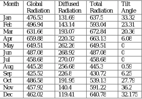
Monthwıse readıngs sımulated by soft-computıng:
For Kolkata (22.5667° N, 88.3667° E),West Bengal, India, the monthly values of the Global Radiation (H) and Diffused Radiation (Hd) has been taken from the NASA website[62]. The values are presented in the form of monthly
average for a year. Whereas, the values of the incident Total Radiation (HT) and that of the tilt angle (β) have been
simulated and found using a program written in GA.
The total radiation that is obtained with the tilt angle of the solar power optimised for a month using genetic algorithm. The global radiation and the diffused radiation has been taken from NASA website for Kolkata for the particular months. GA simulates global radiation and diffused radiations to get the maximum total radiation for the tilt angle. Table 1 shows the simulated monthly data.
Table 1: GA simulated data using NASA statistics.
Month Global
Radiation
Diffused Radiation
Total Radiation
Tilt Angle
Jan 476.53 131.69 637.5 33.32
Feb 496.94 143.14 593.04 23.31
Mar 631.66 193.07 672.84 20.36
Apr 659.88 220.32 663.13 6.08
May 649.51 262.26 649.51 0
Jun 487.08 268.92 487.08 0
Jul 458.68 270.07 458.68 0
Aug 445.28 256.68 445.3 0.59
Sep 425.52 226.8 430.72 6.25
Oct 486.58 191.95 539.13 27.79
Nov 457.92 140.4 591.22 36.2
Dec 462.02 119.41 640.78 32.175
Fig 4: Convergence characteristics of GA for the month of April
First part of the figure shows the convergence characteristics where as second part shows best individual values of the variables, first variable is tilt angle (value is 6.08º), second variable is any day of April and third one is total radiation value (663.13). The same characteristics are coming for the other months of the year.
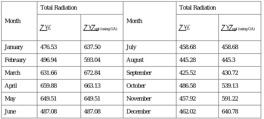
Table 2: Comparing the data with optimised tilt against no tilt.
Month
Total Radiation
Month
Total Radiation
β : 0 β : βopt (using GA) β : 0 β : βopt (using GA)
January 476.53 637.50 July 458.68 458.68
February 496.94 593.04 August 445.28 445.3
March 631.66 672.84 September 425.52 430.72
April 659.88 663.13 October 486.58 539.13
May 649.51 649.51 November 457.92 591.22
June 487.08 487.08 December 462.02 640.78
Table 2 compares the monthly data between the total radiation with optimised tilt and with no tilt to show the power gain achieved.
So after the comparison for Kolkata (22.5667° N, 88.3667° E), using the data’s from GA, The total annual radiation obtained (with βoptimized) : 6809.94 MJ/m2/annum
The total annual radiation obtained (without any tilt) : 6137.60 MJ/m2/annum So the added radiation that can be obtained by optimizing the tilt angle : 672.34 MJ/m2/annum
Thus we get,
→
..
× 100
≈
10.95%
0 2 4 6 8 10
-200 0 200 400
Generation
F
it
n
e
s
s
v
a
lu
e
Best: -0.0510638 Mean: 11.0845
1 2 3
0 500 1000
Number of variables (3)
C
u
rr
e
n
t
b
e
s
t
in
d
iv
id
u
a
l Current Best Individual
Thus by optimising the tilt angle on a monthly basis, a gain of 10.94% can be achieved.
In the second part of this research the hardware model was implemented to check the actual efficiency. The readings were collected from April 22nd, 2016 to May 1st, 2016. The location for this session was Techno India, Salt Lake, [22.5760N, 88.4280E], Kolkata, India.
Tables 3 – 9 show the readings taken from the solar tracker on an hourly basis. The readings were taken on persisting weather conditions from April 22nd, 2016 to May 1st, 2016 (1200 hrs to 1500 hrs each day) . A small load box consisting of LEDs is fabricated to find out voltage, current and power.
Table 3: Apr. 22, 2016. Table 4: Apr. 23, 2016.
Time V I P β
1200 9.9 199.8 1.99 0
1300 9.8 191 1.91 3
1400 9.8 185 1.84 18
1500 9.7 171 1.71 40
Table 5: Apr. 24, 2016. Table 6: Apr. 25, 2016.
Table 7: Apr. 26, 2016. Table 8: Apr. 29, 2016.
Table 9: May 1, 2016.
Time V I P β
1200 9.9 199.8 1.98 0
1300 9.8 191 1.87 4
1400 9.8 185 1.81 20
1500 9.7 171 1.66 41
Time V I P β
1200 9.9 205.1 2.03 0
1300 9.9 197 1.95 3
1400 9.9 191 1.89 17
1500 9.8 180 1.76 38
Time V I P β
1200 9.9 211.7 2.10 0
1300 9.9 200 1.98 3
1400 9.9 195 1.93 17
1500 9.8 185 1.81 36
Time V I P β
1200 9.9 218.2 2.16 0
1300 9.9 209.9 2.08 2
1400 9.9 201 1.99 15
1500 9.8 193 1.89 34
Time V I P β
1200 9.9 223 2.21 0
1300 9.9 216 2.11 2
1400 9.9 209 2.07 11
1500 9.8 200 1.96 27
Time V I P β
1200 9.9 215.6 2.13 0
1300 9.9 206 2.04 2
1400 9.9 198 1.96 16
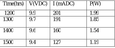
On comparing with both the tables (Table 9 and 10), it is evidently visible that the output power has been massively optimized.
Calculating the increase in output power percentage (by taking the average of each day),
: ( ) ( ) ( )x 100 %
: . .
. x 100 %
: 19.51 %
Using dual axis solar tracker, the same panel output power can be increased by 19.51 %. The difference in the output can easily be understood by Fig. 5.
Fig. 5: Chart showing difference between output power with optimised tilt angle and no-tilt
Table10: The readings for the same hours keeping the solar panel at a normal position without any tilt.
From the readings taken for the month of April, 2016 it can be seen that the optimum tilt angle, β for this month lies within the range 4o-11o. Again from the GA simulation it was found that the optimum angle for the same month was 6.08o. which is within the practical range of the angle found.
So this allows us to limit the tracking to a monthly basis rather than a daily basis for economical purposes. From the above results, it can be seen that for each month an average optimum angle can be calculated. The panel when kept at these angles is supposed to receive the maximum solarradiation. So if the panels are fixed at these particular angles for
2.09 2
1.93 1.82
1.99
1.85
1.54
1.19
0 0.5 1 1.5 2 2.5
1200 1300 1400 1500
P
O
W
ER
TIME
Power (W) (with tilt) Power (W) (with no tilt)
Time(hrs) V(VDC) I (mADC) P(W)
1200 9.9 201 1.99
1300 9.7 191 1.85
1400 9.6 160 1.54
he whole month, optimised electricity production can be guaranteed throughout the month without any need of changing the angles daily. This would ensure the efficient conversion of solar energy to electrical energy without having to spend any extra amount on the tracking part of it.
Table 11: Daily average Power and the range of degree obtained from the readings of the solar tracker.
VI.CONCLUSION
The sun's position seems to change from east to west at a pace of about 10 in every 15 minutes due to the earth's movement about its axis. Solar radiation that can be synthesised by a solar photovoltaic cell comprises of three types, direct, diffused and reflected. Radiations being of different types provide different power output from the panel at different tilt angles. Here tilt angle optimisation is proposed using soft computing approach to receive more power from the very same panel.
The solar panels are relatively expensive for power production when compared to the conventional power methods. So optimising it, to increase its production is always a profitable venture.
This study is directed towards the analysis on the optimisation of the tilt angle of a PV solar panel. In the first phase, the tilt angle was optimized on a monthly basis using popular soft-computing software using genetic algorithms and it was found that approximately a 10.94% power gain can be obtained by optimising the tilt angle alone. It is observed that for best result tilt angle can be optimized within 00 (May) and 32.180 (December) for Kolkata, India [Lat. 22.56670 N, Lon. 88.36670 E].
In the second phase of this study, a dual axis solar tracker was developed using a microcontroller, servo motors and three photo-resistors. During the application of this tracker, it was observed an overall power gain of about 19.51% when compared to the panel kept at no tilt with respect to the ground. The readings for this study were taken at Techno India, Kolkata, India [Lat. 22.5760 N, Lon. 88.4280 E]. This also follows GA based result. The tracker provides an additional safety to the panel from shadows reducing the possibility of hot-spot effect significantly.
An understanding of these angles would permit us to upgrade the tracker in the future so that the panel can be made to face the sun at all times without the need of any light sensor. Following and observing GA based and tracker based result, a rationalize decision making can be possible which lead to a reduction in the cost and also lower electricity input to the system, thus leading to even higher efficiency.
ACKNOWLEDGEMENTS
Authors are thankful to Techno India Engineering College, Kolkata, India for environmental and funding support.
REFERENCES
[1] R. Walraven, “Calculating the position of the sun”. Solar Energy. Vol. 20, pp.393–397, 1977.
[2] V. Poulek,M. Libra, 2007. “New bifacial solar trackers and tracking concentrators”.Solar energy material and solar cell, Vol 51,pp.1-9, 2007. [3] P. Roth, A. Georgiev, H. Boudinov, “Cheap two-axis sun following device”. Energy Con. and Management, Vol 46, pp.1179–1192, 2005. [4] http://www.helmholz.us/smallpowersystems/
[5] T. Tomson, “Discrete two-positional tracking of solar collectors”, Renewable Energy, Vol 33, pp.400–405, 2008.
[6] JT. Agee, A.Obok-Opok, MD. Lazzer, 2007 “Solar tracker technologies: market trends and field applications”, Advanced Materials Research, Vol 18, No.19,pp. 339–344, 2007.
[7] Ai B. Shen, H. Ban, Q. Ji, B. Liao, “Calculation of the hourly and daily radiation incident on three step tracking planes”, Energy Conversion and Management,Vol. 44, .pp.1999–2011, 2011.
DATE Avg. Power Range of Degree
Apr. 22, 2016 1.83 4 - 20
Apr. 23, 2016 1.86 3 - 18
Apr. 24, 2016 1.91 3 - 17
Apr. 25, 2016 1.96 3 - 17
Apr. 26, 2016 2.03 2 - 15
Apr. 29, 2016 2.09 2 - 11
[8] IM. Michaelides, SA.Kalogirou, I.Chrysis,G. Roditis, A. Hadjiyianni, HD. Kambezidis, et al. 1999 “Comparison of performance and cost effectiveness of solar water heaters at different collector tracking modes in Cyprus and Greece”, Energy Conversion and Management,Vol. 40, pp.1287–1303 , 1999.
[9]C. Grass, W. Schoelkopf , et al. “Comparison of the optics of non-tracking and novel types of tracking solar thermal collectors for process heat applications up to 300 8C”, Solar Energy ,Vol. 76,pp. 207–215, 2004.
[10] NH. Helwa, ABG. Bahgat, AMRE Shafee, ETE Shenawy, 2000 “Computation of the solar energy captured by different solar tracking systems”, Energy Sources, Vol. 22, pp. 35–44, 2000.
[11] E. Lorenzo, M. Perez, et al. “Design of tracking photovoltaic systems with a single vertical axis”, Progress in PV Research and Applications, Vol 10, pp.533–543, 2002
[12] YV. Pavel, HJ. Gonzalez, et al. “Optimization of the solar energy collection in tracking and non-tracking PV solar system”, Proceedings of the
1st ICEEE, pp.310–314, 2004.
[13]NH. Helwa, ABG. Bahgat, et al.. “Maximum collectable solar energy by different solar tracking systems”, Energy Sources Vol,22, pp.23–24, 2000.
[14] http://www.labplan.ufsc.br/congressos/PowerTech07/
[15] S. Nann. “Potential for tracking PV systems and V-troughs in moderate climates”, Solar Energy, Vol 45, No.6, pp.385–393, 1990. [16] JD. Felske, “The effect of off-south orientation on the performance of flat-plate solar collectors”, Solar Energy, Vol 20, pp.29–36, 1978. [17] CD. Matthew,D. Wettergreen, D.Villa, “A sun-tracker for planetary analog rovers”, i-SAIRAS, 2005
[18] SA. Kalogirou, “Solar thermal collectors and applications,” Progress in Energy and Combustion Science, Vol 30, pp.231–295, 2004. [19] R. Grena, “An algorithm for the computation of the solar position”, Solar Energy, Vol 82, pp.462–470, 2008.
[20] M. Comsit, I. Visa,:“Design of the linkages type tracking mechanisms of the solar energy conversion systems by using multi body systems method”, IFTOMM, 2007.
[21] ME. Splitt, CP. Bahrmann, “Detection of SIRS solar tracking problems with automated algorithms”, ARM science team meeting,1999. [22] M. Stern, G.Duran, et al. “Development of a low-cost integrated 20-kW-AC solar tracking sub-array for grid connected PV power system applications”, Final technical report. NRELISR-520-2475 9. National Renewable Energy Laboratory, A National Laboratory of the U.S. Department of Energy Managed by Midwest Research Institute for the U.S. Department of Energy; June 1998
[23] MJ. Clifford, D. Eastwood, “Design of a novel passive solar tracker”, Solar Energy, Vol 77, pp.269–280, 2004.
[24] G. Mwithiga, SN. Kigo, “Performance of a solar dryer with limited sun tracking capability”, Journal of Food Engineering, , Vol 74, pp.247–252, 2006
[25] V.Poulek,“Testing the new solar tracker with shape memory alloy actors”, IEEE Photovoltaic Specialists Conference, Vol 1, pp.1131–1133, 1994.
[26] IL Heredia, JM. Moreno, et al.“Inspira’s CPV sun tracking (concentrator photovoltaics)”, Springer, 221–251, 2007.
[27] S. Abdallah,S. Nijmeh, “Two axes sun tracking system with PLC control, Energy Conversion and Management”, Vol 45, pp.1931–1939, 2004 [28] R. Mamlook, S. Nijmeh, SM. Abdallah, “A programmable logic controller to control two axis sun tracking system” , Information Technology Journal , Vol 5, No.6, pp.1083–1087, 2006.
[29] V. Rumyantsev, A. Chalov, E. Ionova, V.Larionov, V.Andreev “Concentrator PV modules with multi-junction cells and primary/secondary refractive optical elements.” ,The 19th European photovoltaic solar energy conference, 2004.
[30] A. Konar,AK. Mandal, “Microprocessor based automatic sun-tracker”, IEE Proceedings Part A Physical Science Measurement and Instrumentation Management and Education Reviews, Vol 138, No.4, pp.237–241, 1991.
[31] Al-Mohamad, A., “Efficiency improvements of photo-voltaic panels using a suntracking system”, Applied Energy, Vol 79, pp. 345–354, 2004. [32] M.Abu-Khader, M.O. Badran, S. Abdallah, “Evaluating multi-axes sun-tracking system at different modes of operation in Jordan”, Renewable and Sustainable Energy Reviews, Vol 12, pp.864–873, 2008.
[33] O. Bingol,A.Altintas, O¨ Ner Y.,“Microcontroller based solar-tracking system and its implementation”, Journal of Engineering Sciences, Vol 12, No. 2, pp.243–248, 2006.
[34] B. Koyuncu, K.Balasubramanian,“A microprocessor controlled automatic suntracker”, IEEE Transactions on Consumer Electronics, Vol 37, No.4, pp..913–917, 1991.
[35] http://ltc.cit.cornell.edu/courses/ee476/FinalProjects/s2005/tp62/website/solartracker. [36] www.girasolar.com
[37] http://engineering.utsa.edu/ee/sd/projects/spring2006/13/Team_13_Final_Presentation.
[38] S. Abdallah, “The effect of using sun tracking systems on the voltage–current characteristics and power generation of flat plate PV”, Energy Conversion and Management, Vol 45, pp.1671–1679, 2004.
[39] JI. Rosell, X.Vallverdu, M. Lecho, M.Ibanez, M. . “Design and simulation of a low concentrating PV/thermal system, Energy Conversion and Management”, Vol 46,. pp.3034–3046, 2005.
[40] Lakeou, S., Ososanya, E., Latigo, B., O., Mahmoud, W., Karanga, G., Oshumare, W., “ Design of a low-cost digital controller for a solar tracking photo-voltaic (PV) module and wind turbine combination system”, 21st European PV solar energy conference, 2006.
[41] O. Aliman, I. Daut, et al. “Simplification of sun tracking mode to gain high concentration solar energy”, American Journal of Applied Sciences, Vol 4, No.3, pp.171–175, 2007.
[42] R. Y.Nuwayhid, F. Mrad, R. Abu-Said, “The realization of a simple solar tracking concentrator for university research applications”, Renewable Energy, Vol 24, pp.207–222, 2001.
[43] K. E. AL-Jumaily, M.K.A. AL-Kaysi.,“The study of the performance and efficiency of flat linear Fresnel lens collector with sun tracking system in Iraq”, Renewable Energy, Vol 14, No.14, pp. 41–48, 1998.
[44] ww.thaiscience.info/article/Khlaichom_P_Sonthipermpoon_K_‘Optimization_of_solar_tracking_system_based_on_genetic_algorithms’_2006// [45] E. R.Rubio, M.G. Ortega, F. Gordillo, et al. ,”Application of new control strategy for sun tracking,” Energy Conversion and Management, Vol 48, pp.2174–2184, 2007.
[46]G. C. Bakos, “Design and construction of a two-axis sun tracking system for parabolic trough collector (PTC) efficiency improvement” Renewable Energy, Vol 31, pp.2411–21, 2006.
[48] J. Armendariz, C.Ortega-Estrada, et al. ,“Dual-Axis Solar Tracking Controller Based on Fuzzy-Rules Emulated Networks and Astronomical Yearbook Records”, Proceedings of the World Congress on Engineering, 2013.
[49] A. Mellit, A. M.Pavan, “A 24-h forecast of solar irradiance using artificial neural network: Application for performance prediction of a grid-connected PV plant at Trieste, Italy,” Solar Energy, Elsevier, Vol 84, pp.807-821, 2010.
[50] A. Moghaddamnia, R.Remesan, M.H. Kashani, et al. “Comparison of LLR, MLP, Elman, NNARX and ANFIS Models with a case study in solar radiation estimation”, Journal of Atmospheric and Solar-Terrestrial Physics, Elsevier, Vol 71, pp. 975–982, 2009.
[51] S. A.Sadyrbayev,A.B.Bekbayev, et al., “Design and Research of Dual-Axis Solar Tracking System in Condition of Town Almaty, Middle-East Journal of Scientific Research”, Vol 17, No.12, pp.1747-1751, 2009.
[52] N. Mohammad, T.Karim. “The design and implementation of hybrid automatic solar system”, International journal of electrical and power engineering (IJEPE), Vol 6, No.3, pp. 111-117, 2012.
[53]. I. Kais, A. Lateef, “A low cost single-axis sun tracker system using PIC microcontroller”, Diyala Journal of Engineering Sciences (DJES), Vol 1,. pp.65-78, 2012.
[54] M.K. Al-Haddad, S. Hassan, “Low cost automatic sun path tracking system”, Journal of Engineering, Vol 1, pp.116-130, 2011.
[55] G. Almonacid, E. Muñoz, et al., “Analysis and performance of a two-axis PV tracker in Southern Spain”, Journal of Solar Energy Engineering,, Vol 133, No.1, pp.1 – 7, 2011.
[56] M. T. Khan,S.M.S. Tanzil, et al., “Design and Construction of an Automatic Solar Tracking System”, 6th ICECE, 2010.
[57] S. Rahman, R.A.Ferdaus, M. A. Mannan, M. A.Mohammed, “Design & Implementation of a Dual Axis Solar Tracking System”, American Academic & Scholarly Research Journal, Vol 5, (1), pp.28 – 32, 2013.
[58] N. Barsoum, “Fabrication of Dual-Axis Solar Tracking Controller Project”, Intelligent Control and Automation, Vol 2, pp.57-68, 2011. [59] S. Deepthi, A.Ponni, R.Ranjitha, R. Dhanabal, “Comparison of Efficiencies of Single-Axis Tracking System and Dual-Axis Tracking System with Fixed Mount”. IJESIT, Vol 2, No.2, pp.425 – 430, 2013.
[60] J. Byeong-Ho,P. Ju-Hoon,K.Seung-Dai, K.Jong-H, “Performance evaluation of dual axis solar tracking system with photo diodes, Electrical
Machines and Systems (ICEMS)”, 2013 International Conference on (IEEE), Busan. pp.414 – 417, 2013.
[61] M. Benghanem, “Optimization of tilt angle for solar panel: Case study for Madinah, Saudi Arabia”. Applied Energy-elsevier, Vol 88, No 4,
pp.1427–1433, 2011
[62]https://eosweb.larc.nasa.gov/cgi-bin/sse/grid.cgi?&num:269113&lat:22.567&hgt:100&submit:Submit&veg:17&sitelev:&email:[email protected]&p:grid_id&p:exp_dif&step:2&lo n:88.367