Issue 1
CALL STACKER
V-5325150
byPagePac
®INTRODUCTION
The Digital Voice Announcer Call Stacker is a microprocessor based audio recording and announcement system. The Call Stacker is used in conjunction with a paging system to provide buffered announcement play to the paging system.
SPECIFICATIONS
(also see Table 3)FEATURES
• Maximum Record Time - 3 Minutes • Battery Backup for up to 2 Hours
• Maximum of 30 Announcements • Rack Mountable - 19” (48.3cm)
• Announcement Verification • Pause Override Control
• 5 Analog Station Port Input Channels • Provides Audio Output and a Contact Closure
Power Requirements
Dimensions/Weight
• 115 Vac, 60 Hz • 16.25”W x 1.75”H x 9.25”D
(41.28cm x 4.45cm x 23.50cm) • 13.0 lbs (5.85 kg)
Environment
• 19”W (48.3cm) with rack brackets• Temperature: 0 to 40°C (32 to 104°F)
• Humidity: 5 to 95%
OPERATION
The Call Stacker features 5 Input Station (recording) channels, a single Page Output channel and 3 minutes of recording time.
Up to 5 announcements can be recorded simultaneously, virtually eliminating frustrating delays
encountered when accessing the paging system. The recorded announcements are queued in order so the first complete announcement recorded, plays first, followed by the second announcement, etc. The Call Stacker allows users to verify their announcements before they play to the paging system. If a user is not content with their recorded announcement, they can re-record it repeatedly until they are satisfied.
The Call Stacker's Page Output channel interfaces to the paging system's control unit. Once an
announcement is recorded, the Call Stacker plays the announcement over the Page Output channel to the paging system. While the recorded announcement is playing, the Page Output channel provides a contact closure to the paging system.
Once the complete recorded announcement plays to the paging system, it is erased from the Call Stacker, freeing up the recording time for new announcements.
NOTE: Associated equipment would need to be powered by an uninterrupted power supply.
The Call Stacker is equipped with battery backup which allows it to operate for up to two hours, from a fully charged battery, if a power failure occurs.
INSTALLATION
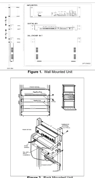
1. Attach the reversible 19/23" brackets to the Call Stacker using the 6-32 x 3/8" screws provided, then secure the Call Stacker to a back board or into an equipment rack.
Figure 1. Wall Mounted Unit
FRONT DETAIL
4.0" TYPICAL
POWER STRIP REAR DETAIL
ZONE WIRING
C O M B I N A T I O N P A N H E A D P I L O T P O I N T # 1 2 - 2 4 ( T Y P I C A L )
19''
10'' TEL LINE
INPUT CHANNELS
POWER
POWER P a g e P a c P l u sâ
AmpliCenter D300
P a g e P a c P l u sâ Controller
Call Stacker
P a g e P a c P l u sâ AmpliCenter D300
P a g e P a c P l u sâ
Controller
2. Set the option switch on the Call Stacker (see Figure 5) for the desired system configuration (refer to Table 1).
Table 1. Option Switch Setting
NOTE: When switch #7 is “OFF”, there will be no delay in time from when the paging system zone is accessed until the time when the message is sent. When switch #7 is “ON”, there will be a 2 second delay from when the paging system/zone is accessed until the time when the message is sent. The delay is installed in order for a Confirmation/Pre-announcement tone (if available or optioned) to be played over the system before the message is sent.
3. Connect the Call Stacker to the paging system (see Figure 4):
• Connect the Call Stacker's Pause Override Control input to the attendant override (attendant access control leads) or incoming alarm signal from the paging system.
• Connect one or more of the Call Stacker's Input Station channels to PBX/KTS analog station inputs on the telephone system through FCC/DOC approved modular jacks. Connect the Call Stacker's Page Output channel to the paging system as shown in Figures 4 and 5 through an FCC/DOC approved modular jack. The control contact signal is used to secure and release the paging system controller.
SET SWITCH
# 1 TO
SET SWITCH
# 2 TO
SET SWITCH
# 3 TO
SET SWITCH
# 4 TO
SET SWITCH
# 5 TO
SET SWITCH
# 6 TO
SET SWITCH
# 7 TO
Number of DTMF Digits in Zone Code
0 ON ON — — — — —
2 OFF ON — — — — —
3 ON OFF — — — — —
4 OFF OFF — — — — —
Voice Prompts
None — — ON ON — — —
English only — — OFF ON — — —
Spanish only — — ON OFF — — —
English/Spanish — — OFF OFF — — —
Length of Recording Cut Off (when user hangs up during recording)
None — — — — ON ON —
0.25 sec — — — — OFF ON —
0.50 sec — — — — ON OFF —
0.75 sec — — — — OFF OFF —
Confirmation or Pre-Announcement Tone
Figure 3. Page Output Channel Connection of Call Stacker
Figure 4. Connection to Paging System
NOTE: The zone contact closure output must be programmed as a Zone Output type “AA READY” if the Attendant Access input is used.
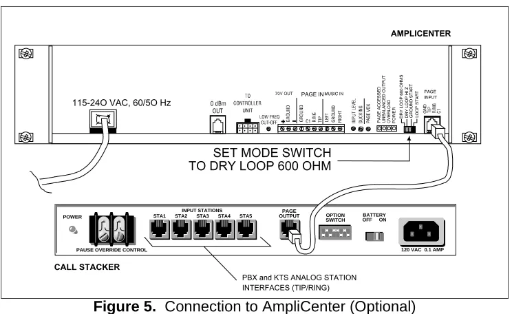
Figure 5. Connection to AmpliCenter (Optional)
A M P L I C E N T E R
P A G E I N
1 1 5 - 2 4 O V A C , 6 0 / 5 O H z
S E T M O D E S W I T C H T O D R Y L O O P 6 0 0 O H M
C A L L S T A C K E R POWER
PAUSE OVERRIDE CONTROL 120 VAC 0.1 AMP
STA1 STA2 STA3
INPUT STATIONS
STA4 STA5
PAGE
OUTPUT OPTION
SWITCH OFF ONBATTERY
NOTE: PBX and KTS stations must have the ability to send a forward disconnect to the Call Stacker's Station inputs.
4. Connect the detachable power supply cord to a 110/120 VAC outlet and the Call Stacker and verify the Power LED illuminates.
5. Turn the battery switch ON.
CONTROLS AND INDICATORS
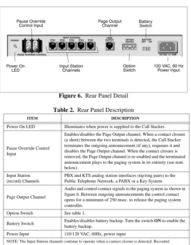
Figure 6.
Rear Panel Detail
Table 2.
Rear Panel Description
ITEM DESCRIPTION
Power On LED Illuminates when power is supplied to the Call Stacker.
Pause Override Control Input
Enables/disables the Page Output channel. When a contact closure (a short) between the two terminals is detected, the Call Stacker terminates the outgoing announcement (if any), requeues it and disables the Page Output channel. When the contact closure is removed, the Page Output channel is re-enabled and the terminated announcement plays to the paging system in its entirety (see note below).
Input Station (record) Channels
PBX and KTS analog station interfaces (tip/ring pairs) to the Public Telephone Network, a PABX or a Key System.
Page Output Channel
Audio and control contact signals to the paging system as shown in figure 6. Between outgoing announcements the control contact opens for a minimum of 250 msec. to release the paging system controller.
Option Switch See table 1.
Battery Switch Enables/disables battery backup. Turn the switch ON to enable the
battery backup.
Power Input 110/120 VAC, 60Hz, power input
RECORDING ANNOUNCEMENTS
VOICE PROMPTS ENABLED
1. Dial up the input station connected to the Call Stacker. The Call Stacker answers the station and responds “Enter zone code (Marque el codigo de la zona)”. Proceed to step 2.
2. Enter a DTMF tone sequence using the telephone keypad to select a paging zone.
• Once the required number of DTMF digits (see Table 1) are entered, the Call Stacker responds “Start recording, press the pound key to end or hang up (Empieze a grabar el mensage, para ter-minar la grabación cuelge o marque la tecla de numero)” followed by a high tone.
Proceed to step 3.
NOTE: If the number of digits in the paging zone is set to 0 (see Table 1), the Call Stacker answers the station and responds “Start recording, press the pound key to end or hang up (Empieze a grabar el men-sage, para terminar la grabación cuelge o marque la tecla de numero)” followed by a high tone. Skip step 2 and proceed to step 3.
Important: If all the recording time is used up, the Call Stacker answers the station and responds with “No recording time available (No hay tiempo de grabación disponible)” or “Message not recorded (No hay mensajes grabados)” then disconnects. If this occurs wait a few seconds before re-attempting to record the announcement.
3. Record the announcement. To end recording, either:
• Hang up to enter the recorded announcement into the queue, or
• Press the “#” key to hear the recorded announcement. The Call Stacker responds “Hang up if fin-ished, press zero to re-record or stay on the line to review your message (Cuando termine de gra-bar cuelge, marque la tecla cero para regragra-bar, o siga en la linea para escuchar el mensage grabado)”, plays back the recorded announcement and then responds “Hang up if finished, press zero to re-record (Cuando termine de grabar cuelge, marque la tecla cero para regrabar)”. Press the “0” key to re-record the announcement and return to step 2 or hang up to accept the announce-ment and enter it into the queue.
NOTE: Press the “#” key while the voice prompts are playing to interrupt (and skip) them
VOICE PROMPTS DISABLED (Switch 3 & 4 ON)
1. Dial up the input station connected to the Call Stacker and wait for the Call Stacker to answer the station and respond with a high tone. Proceed to step 2.
NOTE: If the number of digits in the paging zone code is set to 0 (see Table 1), skip step 2 and proceed to step 3.
2. Enter a DTMF tone sequence using the telephone keypad to select a paging zone. Once the required number of DTMF digits (see Table 1) are entered, the Call Stacker responds with a high tone. Proceed to step 3.
• Press the “#” key to hear the recorded announcement. The Call Stacker responds with a high tone, plays back the recorded announcement and then responds with a second high tone. Press the “0” key to re-record the announcement and return to step 2 or hang up to accept the announcement and enter it into the queue.
Important: If all the recording time is used up, the Call Stacker responds with two consecutive low tones then disconnects. If this occurs your announcement has not been recorded. Wait a few seconds before re-attempting to record the announcement.
ANNOUNCEMENT PLAYBACK
Once a recorded announcement is entered into the queue, the Call Stacker immediately closes the con-trol contact on the Page Output channel to access the paging system concon-troller.
The Call Stacker then plays out the recorded DTMF sequence to select the paging zone followed by the recorded announcement.
At the end of the announcement the Call Stacker erases the announcement and opens the control con-tact on the Page Output channel to release the paging system controller.
NOTE: If more than one announcement is in the queue, the control contact remains open for a minimum of 250 msec.
Important: If at any time a contact closure is detected on the Pause Override Control Input, the Call Stacker immediately terminates the outgoing announcement and requeues it for playback in its entirety once the contact closure is removed.
SPECIFICATIONS
Table 3.
Call Stacker Unit Specifications
SPECIFICATION DESCRIPTION
Recording Time 3 minute base unit.
Input Lines 5 analog station ports.
Output Lines 1 page output channel.
Number of stacked Announcements
30 individual announcements.
Altitude: Sea level to 10,000 ft. operational (1048 to 648 millibars) 40,000 ft. max. shipment.
Environmental Locate in an area free of excess moisture, corrosive gases, dust, and chemicals.
Battery Backup Allows up to two hours of operation during a power failure. Total charge time 48 hours.
Frequency Response 200 Hz to 3.4 kHz ( ±3 dB).
Output Level –9 dBm.
Control Contact Rating
TECHNICAL ASSISTANCE
When calling, have a VOM and a telephone test set available and call from the job site.
Call (540) 427-3900 and ask for PagePac Technical Support, or call (540) 427-6000 for Valcom 24-hour Automated Support or visit our websites at http://www.pagepac.com and www.valcom.com.
Should repairs be necessary, attach a tag to the unit clearly stating company name, address, phone number, contact person, and the nature of the problem. Send the unit to:
Valcom, Inc. PagePac® Repair Dept.
5614 Hollins Road Roanoke, VA 24019-5056
FCC
This equipment complies with Part 68 of the FCC rules. On the rear of the digital voice announcer is a label that contains, among other information, the FCC registration number and ringer equivalence num-ber (REN) for this equipment. If requested, this information must be provided to the telephone company.
The USOC for this equipment is RJ11C. The facility interface code is 02LS2 and the service order code is 9.0F. This equipment is hearing aid compatible.
The ringer equivalence number (REN) is used to determine the quantity of devices which may be con-nected to the telephone line. Excessive REN's on the telephone line may result in the devices not ringing in response to an incoming call. In most, but not all areas, the sum of the REN's should not exceed five (5.0). To be certain of the number of devices that may be connected to the line, as determined by the total REN's contact the telephone company to determine the maximum REN for the calling area.
If the digital voice announcer causes harm to the telephone network, the telephone company will notify you in advance that temporary discontinuance of service may be required. But if advance notice isn't practical, the telephone company will notify the customer as soon as possible. Also, you will be advised of your right to file a complaint with the FCC if you believe it is necessary.
The telephone company may make changes in it's facilities, equipment, operations, or procedures that could affect the operation of the equipment. If this happens, the telephone company will provide advance notice in order for you to make the necessary modifications in order to maintain uninterrupted service.
This equipment cannot be used on public coin service provided by the telephone company. Connection to Party Line Service is subject to state tariffs. Contact the state public utility commission, public service commission or corporation commission for information.
FCC Registration Number: F4PCAN-20988-AN-N
DOC
The Canadian Department of Communications label identifies certified equipment. This certification means that the equipment meets certain telecommunications network protective, operational and safety requirements. The Department does not guarantee that the equipment will operate to the user's satisfac-tion.
Before installing this equipment, users should ensure that it is permissible to be connected to the facili-ties of the local telecommunications company. The equipment must also be installed using an approved method of connection. In some cases, the company's inside wiring associated with a single line individ-ual service may be extended by means of a certified jack-plug-cord ensemble (telephone extension cord). The customer should be aware that compliance with the above conditions may not prevent degra-dation of service in some situations. Existing telecommunications company requirements do not permit their equipment to be connected to customer-provided jacks, except where specified by individual tele-communications company tariffs.
Repairs to certified equipment should be made by an authorized Canadian maintenance facility desig-nated by the supplier. Any repairs or alterations made by the user to this equipment, or equipment mal-functions, may give the telecommunications company cause to request the user to disconnect the equipment.
Users should ensure for their own protection that the electrical ground connections of the power utility, telephone lines and internal metallic water pipe system, if present, are connected together. This precau-tion may be particularly important in rural areas.
Caution: Users should not attempt to make such connections themselves, but should contact the appro-priate electrical inspection authority, or electrician, as approappro-priate.
DOC Certification Number: 5576106A
Load Number: 26
The Load Number (LN) assigned to each terminal device denotes the percentage of the total load to be connected to a telephone loop which is used by the device, to prevent overloading. The termination on a loop may consist of any combination of devices subject only to the requirement that the total of the Load Numbers of all the devices does not exceed 100.