IoT Based Smart Electricity Meter Reading
and Control System
Monish Mohan1, Gachu Krishnan2, Dias Antony3, S. Ramraj4, K. Chithra5
UG Student, Dept. of EIE, PSN College of Engineering and Technology, Tirunelveli, Tamilnadu, India1 UG Student, Dept. of EIE, PSN College of Engineering and Technology, Tirunelveli, Tamilnadu, India2 UG Student, Dept. of EIE, PSN College of Engineering and Technology, Tirunelveli, Tamilnadu, India3 Assistant Professor, Dept. of EIE, PSN College of Engineering and Technology, Tirunelveli, Tamilnadu, India4 Assistant Professor, Dept. of EIE, PSN College of Engineering and Technology, Tirunelveli, Tamilnadu, India5
ABSTRACT: We can see a person standing in front of our house from electricity board, whose duty is to read the energy meter and handover the bills to the owner of that house every month. This is nothing but meter reading. According to that reading we have to pay the bills. The main drawback of this system is that person has to go area by area and he has to read the meter of every house and handover the bills. Many times errors like extra bill amount, or notification from electric board even though the bills are paid are common errors. To overcome this drawback we have come up with an idea which will eliminate the third party between the consumer and service provider, even the errors will be overcome. In this paper the idea of smart energy meter using IoT and Arduino have been introduced. In this method we are using Arduino because it is energy efficient i.e. it consume less power, it is fastest and has two UARTS. In this paper, energy meters which is already installed at our houses are not replaced, but a small modification on the already installed meters can change the existing meters into smart meters. The use of GSM module provides a feature of notification through SMS. One can easily access the meter working through web page that we designed. Current reading with cost can be seen on web page. Automatic ON & OFF of meter is possible. Threshold value setting and sending of notification is the additional task that we are performing)
KEYWORDS: Energy meter,Arduino,GSM module,Threshold value
I.INTRODUCTION
In the present billing system the distribution companies are unable to keep track of the changing maximum demand of consumers. The consumer is facing problems like receiving due bills for bills that have already been paid as well as poor reliability of electricity supply and quality even if bills are paid regularly. The remedy for all these problems is to keep track of the consumers load on timely basis, which will held to assure accurate billing, track maximum demand and to detect threshold value. These are all the features to be taken into account for designing an efficient energy billing system.
system continuously records the reading and the live meter reading can be displayed on webpage to the consumer on request. This system also can be used to disconnect the power supply of the house when needed.
II.ARCHITECHURAL MODEL
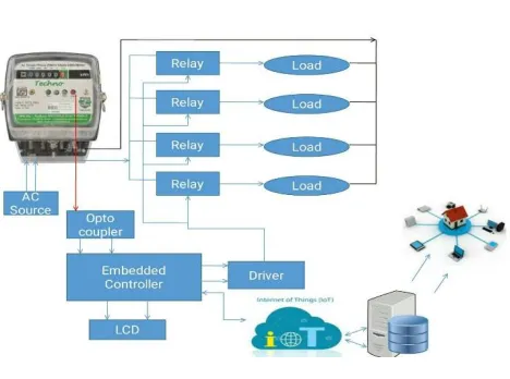
Fig 1: Architectural Diagram
When the various appliances of the household consume energy the energy meter reads the reading continuously and this consumed load can be seen on meter.
We can see that the LED on meter continuously blinks which counts the meter reading.
Based onthe blinking, the units are counted. Normally, 3200 blinks is one unit.
In our project we are trying to develop, a system in which Arduino Uno act as main controller, which continuously monitor energy meter.
As per the blinking of LED on energy meter the Arduino will measure the unit consumption.
The measured reading with the calculation of the cost will be continuously displayed on web page that we have designed.
Threshold value can be set on webpage with the help of Wi-Fi, as per the consumer’s requirement. When the consumers reading will be near about to the set threshold value it will send a notification value to the consumer.
This threshold value notification will increase the awareness amongst the consumer about the energy.
When the consumer gets the notification he can visit the webpage and change the threshold value.
If the consumer is not aware with the threshold notification, then the meter will automatically get off. Then the consumer has to visit the webpage again and increment the threshold value. By the incrementation, the meter will automatically get ON.
Finally the overall monthly bill with cost will be sent to customer as well as service provider in the form of text at first day of every month
III.HARDWARE AND SOFTWARE COMPONENTS
A.ENERGY METER:
product and give instantaneous power. This power is integrated over a time interval, which gives the energy utilized over that time period.
B.SIGNAL CONDITIONER (P817):
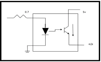
Fig 2: Signal Conditioning Circuit
Above shown is the simple internal working of optocoupler P817 which we are using as signal conditioning block. As we can see on a working meter that one LED continuously blinks, it is nothing but indicates the count of power. The LED whenever blinks it produces only 0.7v which is not suitable for Arduino board to capture, so to remove this error we are using this block. When the LED blinks the diode will conduct, transistor will get active and it will give 5v at output which we are externally giving to transistor. Whenever LED will blink the 5v supply will be provided to Arduino board and it will count them. We are using signal conditioning block to increase voltage.
C.ARDUINO UNO (ATMEGA 328):
Arduino board is the heart of our system. Entire functioning of system depends on this board. Arduino reacts to the 5v supply given by opto-coupler and keeps on counting the supply and then calculates the power consumed and also the cost. This data, it continuously stores on webpage, so that users can visit any time and check their consumption. It even reacts accordingly as per programed, to the situations like message sending during threshold value etc.
D.MAX 232:
We are using MAX 232 for serial communication with the components that are GSM module and Wi-Fi module MAX232 is used to provide TTL to the components as per the requirement. GSM needs TTL so it is connected to Arduino through MAX232. Some Wi-Fi module doesn’t require TTL because it’s already build in it and some may require based on its working.
E.GSM MODULE (SIM900):
GSM stands for Global System for Mobile communication. It is widely used mobile communication modem system in the world. GSM is an open and digital cellular technology used for transmitting mobile voice and data services operates at the 850MHZ, 900MHZ, 1800MHZ, 1900MHZ frequency bands. It has ability to carry 64kbps to 120Mbps of data rates. In our system GSM is used to send the notification of threshold reaching to consumer and for sending message of total consumption of unit with cost to the service provider and consumer.
F.Wi-Fi MODULE (ESP8266):
G.WEBPAGE (HTML):
We designed webpage for operating Arduino and Energy Meter with the help of HTML. HTML stands for Hypertext Markup Language. It is a standard markup language for creating web pages and web applications with Cascading Style Sheets (CSS) and JAVA scripts. It forms a triad of cornerstone technologies for World Wide Web. Web browser receives HTML documents from a Webserver or from local storage and render them into multimedia webpages.HTML describes the structure of web page semantically and originally included cues for the appearance of the document. HTML elements are the building blocks of HTML pages
H.DRIVER CIRCUIT (moc3071):
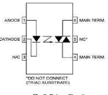
Fig 3: Driver Circuit
It is a 6 pin device known as opto coupler or opto isolator. In our project we are using this opto coupler to cut off the AC load. It is connected to the SSR to cut off the AC load.
I.SWITCHING DEVICE:
In our system we are using SSR as switching device even though we can use RELAY because SSR is highly advantageous. We are using switching device to switch the energy meter. For ON and OFF purpose of meter we are using switching block. SSR stands for SOLID STATE RELAY. Why SSR instead of RELAY?
Both are used as AC switching device, but if switching speed is high then SSR is suitable, if switching speed is slow then RELAY is used.
Relay life decreases as number of usage time increases, but in SSR there is no change.
For driving RELAY, current or power required is more comparatively to SSR.
For switching SSR requires 15amp, whereas RELAY needs (30amp,50amp,90amp) as per requirement.
IV.EQUATIONS AND MATHEMATICAL CALCULATION
Our system does not contain very vast and difficult calculations. Usually different meters have different readings. Some have,
1500 blinks = 1 unit
Mostly, 3200 blinks = 1 unit depends on manufacturer.
In our case 3200 blinks of LED is 1 unit. But for practical purpose, Assumption we made in our system,
5 blinks = 1 unit of power consumption.
Basically,
No. of units (Y) = (X/3200) But in our case,
Y= (X/5)
Assume that 1 unit cost = 5rs.
Z= Y * 5rs For Threshold,
Assumed threshold set value will be = 5 units for practical. If units reach,
Threshold value – 1 unit = 5-1 = 4 units,
Notification will be send to consumer, if consumer doesn’t react and increase the threshold value then meter will automatically get OFF. Again to turn it ON consumer has to visit webpage again to increase threshold value. For practical purpose increment and decrement of threshold can be done by +5units or -5units.
Normally, basic unit of electricity is Kilowatt hour (KWh). 1kWh = 1000 watt for 1 hour.
Example, Ten 100watt bulbs used for 1 hour gives 1kWh.
V.OVERVIEW OF INTERNET OF THINGS
Fig4: IoTworking
Fig 5: Interfacing of Hardware
VI. RESULT AND DISCUSSION
1] Our proposed system web page, where threshold is taken as 5units. Forward represents +5 and reverse -5 units. Current unit with cost will be displayed
2] When threshold is about to over the following message will be sent to consumer
Fig 7: Warning Message
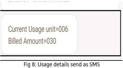
3] Monthly consumption of power will be send as message to the consumer with total bill of electricity.
Fig 8: Usage details send as SMS
4] The monthly bill with unit consumption and user Id will be sent to service provider
Fig 9: Final Usage details send to the user
VII.CONCLUSION
REFERENCES
[1] Himshekhar Das, L.C.Saikia, “GSM Enabled Smart Energy Meter and Automation of Home Appliances”, PP-978-14678-6503-1, 2015 IEEE.
[2] Ofoegbu Osita Edward, “An Energy Meter Reader with Load Control Capacity and Secure Switching Using a Password Based Relay Circuit”,
PP-978-1-4799-8311-7, ‘ Annual Global Online Conference on Information and Computer Technology’, IEEE 2014.
[3] Yingying Cheng, Huaxiao Yang, Ji Xiao, Xingzhe Hou, “Running State Evaluation Of Electric Energy Meter”, PP978-1-4799-4565-8,
‘Workshop on Electronics, Computer and Applications’, IEEE 2014.
[4] Sahana M N, Anjana S, Ankith S,K Natarajan, K R Shobha, “Home energy management leveraging open IoT protocol stack “, PP-
978-1-4673-6670-0, ‘Recent Advances in Intelligent Computational Systems (RAICS)’, IEEE 2015.
[5] Luigi Martirano,Matteo Manganelli,Danilo Sbordone,‘‘Design and classification of smart metering systems for the energy
diagnosis of buildings’’ IEEE 2015.
[6] J. Widmer, Landis,” Billing metering using sampled values according lEe 61850-9-2 for substations”,IEEE 2014.
[7] Cheng Pang,Valierry Vyatkin,Yinbai Deng, Majidi Sorouri, “Virtual smart metering in automation and simulation of energy efficient lightning
system” IEEE 2013.
[8] Amit Bhimte, Rohit K.Mathew, Kumaravel S, “Development of smart energy meter in labview for power distribution systems”, “IEEE
INDICON 2015 1570186881”, 2015.
[9] H. Arasteh, V. Hosseinnezhad, V.Loia, A.Tommasetti, O.Troisi, M.Shafie Khan, P.Siano, “IoT Based Smart Cities: A survey”IEEE
978-1-5090-2320-2/1631.00,2016.
[10] Clement N. NYIRENDRE, Irvine NYANDOWE, Linda SHITUMBAPO, “A comparison of the collection tree protocol (CTP) and AODV