Development of a Low Cost Under-Voltage
and Over-Current Protection Device
Sourav Ghosh1, Soumik Bakshi2, Saurav Ghosh3, Rahul Kundu4, Indrajit Koley5 B.Tech Student, Dept. of EE, Siliguri Institute of Technology, Siliguri, WB, India1, 2, 3, 4
Assistant Professor, Dept. of EE, Siliguri Institute of Technology, Siliguri, WB, India5
ABSTRACT: This paper presents the design and construction of a low cost under-voltage and over-current protective device, which was fabricated using a comparator, IC, Transistor and other discrete devices. The comparator LM324 is at the heart of the device which performs the major control of the device. The device is simple and of low cost. The required set voltage range for the device to allow supply to the connected load at the output varies from 200 – 230 Volts. It can be used to protect loads such as refrigerator, T.V., VCR/DVD players etc. from undesirable under voltages and over currents, as well as surges caused due to sudden failure/resumption of mains power supply. It protects the load when (1) the input voltage to the motor drops below a particular value, (2) the current through the motor exceeds a particular value, (3) both the current increases beyond a particular value and the voltage drops to a particular value. This device can be used directly as a standalone equipment between the mains supply and the load, or it may be inserted between an existing automatic/manual stabilizer and the load.
KEYWORDS: Comparator, over current, Protection, under voltage.
I.INTRODUCTION
Voltage irregularities are one of the greatest power quality issues facing industry and home today and often times, is responsible for damaging valuable electrical equipment. Electrical Power System protection is required for protection of both user and the system equipment from fault, hence electrical appliances are not allowed to operate without any protective device installed. Power System fault is defined as undesirable condition that occurs in the power system, and the undesirable conditions are short circuit, current leakage, ground short, over current, under and over voltage. The ability of protection system is demanded not only for economic reason but for expert and reliable service (Bayindar et al., 2008).
Technically speaking, an under voltage condition is reached when the voltage lags the nominal voltage by 10% for more than 1 minute. Short duration voltage events can also occur such as transients (both impulsive and oscillatory), sags/dips and swells. Short duration intermittent supply failures can last anywhere from 0.5 cycles up to 1 minute and can be caused by a number of occurrences such as supply system faults, equipment failures, or malfunctions in control equipment.
Over current or excess current is a situation where a larger than intended electric current exists through a conductor, leading to excessive generation of heat, and the risk of fire or damage to equipment. Under-voltage might result into brownout, distortion or permanent damage while for overcurrent causes include short circuits, excessive load, incorrect design, or a ground fault. Fuses, circuit, temperature sensors and current limiters are commonly used protection mechanisms to control the risks of overcurrent.
Owing to the incessant damages done by fluctuations in the power supply, there is dire need to address the problem through other alternatives, which give birth to design and construction of an equipment to protect the connected loads against under voltage supply. Under voltage and over current protection is needed between supply terminal and the appliances (connected loads).
II.LITEARTURE SURVEY
from the supply mains. According to the authors, the ability of protection system is demanded not only for economic reason but for expert and reliable service.
Ponnle A. A, Omojoyegbe M. O.(2014) [7], presented a low cost under voltage and over current protection device with a micro controller. The main purpose of the device is to isolate the load from over voltage and under voltage conditions by controlling the relay tripping coil using a PIC micro controller. The microcontroller will compare the supply voltage with the desired pre-set voltage and will operate the tripping coil in the relay if the input voltage falls below or above the pre-set range of values. The design and the programming was simulated several times on Proteus software until the code for the design worked satisfactorily before the final programming of the microcontroller and assembly of the components. The type of programmer used for the microcontroller is a USB programmer, and the programming code used is compiler CCS. The programming of the microcontroller was done by first writing the program code in C#, after which it was compiled using the CCS compiler; then later the hex file was burned to the PIC through the USB programmer. The device is well calibrated and manually tested. The preset was set at the voltage 200-240 volts. This device is found to be economical, easier to maintain and repair. The device cost about $50 to produce.
Girish Chandra Thakur (2015) [8], presented a research paper on “Implementation of Single Phasing, Over Voltage, Under Voltage, and Protection of Three Phase Appliances without Using Microcontroller”. This paper tends to develop for protection for costly appliances which require three-phase AC supply for operation. Failure of any of the phases or sudden change in voltage makes the appliance prone to erratic functioning and may even lead to failure. Hence it is of paramount importance to monitor the availability of the three-phase supply and proper voltage supply and switch off the appliance in the event of failure of one or two phases or if required voltage level is not available. The power to the appliance should resume with the availability of all phases of the supply with proper voltage level. The main advantage of this protector circuit is that it protects three-phase appliances from failure of any phase as well as from fluctuation of voltage. The concept in future can be extended to developing a mechanism to send message to the authority via SMS by interfacing GSM modem.
Manish Paul (2014) [9], presented a paper on “Simulation of overvoltage and under voltage protection”. This paper illustrates modelling and simulation of overvoltage and under voltage protection scheme. The method is based upon the operation of relay under overvoltage and under voltage faults. The term power quality is used to describe as the quality of power that is given as input to various electrical load and ability of load to function properly. Without proper power the devices may mis-operate or fail. There are many ways in which electric power can be poor quality and many more causes for such poor quality. Among the various power quality problems, overvoltage and under voltage are frequent and severe. This paper demonstrates power quality, various causes and effects of overvoltage and under voltage, and their protection. The test model of 230V, 50 Hz, has been designed in PSIM Demo Version 9.2.1.100.
Changchun Chi (2013) [10], discussed about research of the under voltage tripper with overvoltage protection function. This paper designs a new under voltage tripper that has the function of overvoltage protection, to solve the problem which the under voltage tripper coil can be burned down easily when the voltage fluctuates largely, causes the operating region of the under voltage tripper with the high voltage dead areas, improves the reliability of circuit-breaker and ensures the electric circuit normal operation.
III.MATERIALS AND METHODS
Figure-1 A. Brief Explanation of each blocks-
I. AC INPUT-This is the input supply from where this device will be energized. This also supplies the load directly which is connected through the hall effect current sensor and relay terminals
(COM and NC). The circuit will connect the load with supply when the voltage is above 200V and the current is below 5A.
II. Power Supply- The power supply uses a step downtransformer to step down the input mains voltage to a voltage level suitable for the electronics within the device. A 230/18V transformer, with four diodes for full wave rectification is used to convert the ac voltage to a pulsating dc voltage followed by a filter, comprising of a capacitor to filter out (smooth) the pulsation (Close and Yarwood, 1979; Maddock and Calcuta, 1994; Ian, 2000).
After the rectification and smoothening, a sample of the output voltage is fed to the comparator through a potentiometer. This voltage is unregulated and therefore varies as the input mains voltage varies. The output voltage form full bridge rectifier is also passed to an LM7812 positive voltage regulator to provide a regulated +12 V supply to provide a fixed value with which the unregulated voltage will be compared.
There is another voltage regulator LM7805,which is fed supply from LM7812.Its output is smoothened using capacitors and fed to the input of ACS712, which requires +5V as input.
III. ACS712 Current Sensor-To provide overcurrent protection a Hall Effect current sensor is used. The load is fed from power supply is fed through it. It does not change the current being supplied to the load. If current more than 5A is flowing to the load, it gives an output of +5V. This +5V output is used to drive the relay along with the output voltage of LM324 by means of IC7404 and IC7408.
Figure-2
I. Logic gates(IC7404 & IC7408)-Two logic gates namely IC7404 (NOT) and IC7408 (AND) are used to combine the outputs of ACS712 (current sensor) and LM324 (comparator) and drive the relay. First the output form ACS712 is inverted using IC7404 and then output from LM324 and IC7404 is combined using IC7408. In normal conditions IC7408 produces a high output which will be sufficient to drive the relay.
B. Relay Driver Design Analysis
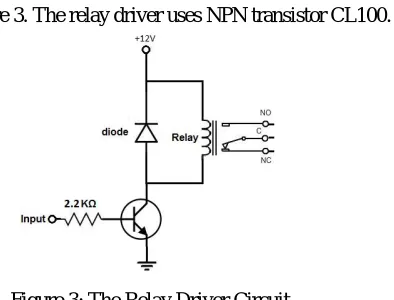
The relay driver circuit is shown in Figure 3. The relay driver uses NPN transistor CL100.
Figure 3: The Relay Driver Circuit
The relay coil is connected between the positive rail and the collector of the transistor. When the input signal passes through the resistor to the base of the transistor, it conducts and activates the relay. Since a relay coil is not only an electromagnet but also an inductor (Gurevich and Vladimir, 2005), a flyback diode D1 in parallel with a resistor is used to eliminate fly back, which is the sudden voltage spike seen across an inductive load when its supply voltage is suddenly reduced or removed. The diode also clamps the voltage across the coil to about 0.7V protecting the transistor and other associated components. The stored energy dissipates quickly in the diode and the resistor. The diode used is IN4007.
DC current gain of the transistor, β is expressed as (Maddock and Calcuta, 1994),
…………..………… (1)
where IC is the collector current (through the relay coil), and IB is the base current.
To calculate the value of the base resistor, the following were considered:
VIN = 5V, and the relay that is used has a coil resistance of 120Ω.
Therefore, the relay coil current = collector saturating current = ICSAT= 12V/120Ω = 100mA.
Assuming β = 75 (for CL100),
I
B
I
CSAT
……… (2)
IB = 100/100 =1mA.
The actual base current flowing, IBSAT must be higher than the calculated base current IB to ensure base saturation. The
base resistor must be able to provide this saturating base current.
Using a 1KΩ resistor would ensure that the transistor is fully “ON” when current passes out from the micro-controller
I
BSAT
V
o
V
BE...(3)
R
1=(5 – 0.7)/1x103
=4.3mA which is >1mA.
IV.EXPLANATION AND CIRCUIT DIAGRAM
The circuit diagram of the developed device is shown in Figure 4. The input mains supply is stepped down by the centre tapped transformer to 18V at input mains voltage of 230Vac.transformer is connected with 4 diodes provide the full wave rectification, for that the voltage converts to 18V DC.Diode 5’ is used here so that the current entering in the circuit could not revert back to the supply. An electrolytic capacitor ‘C1’ is used with rating of 1Uf/63V. Because of its low capacitance, it will have a very low time constant. Current from the rectifier bridge charges the capacitor, and then it discharges through the resistor ‘R2’ and the variable resistor.The total voltage across the resistors are 18V. According to voltage divider rule we can say that the voltage across the variable resistor is- 18*Vr/(R2+Vr)[Supposing the resistance of variable resistor is Vr]. So with changing the input from 230V to any values, the voltage across the Vr will also change due to the transformer action. Thus we have set up a voltage with lower value
which will be analogous to input. This value is taken as an input to the comparator’s (LM324) non-inverting terminal. Now to set up a reference voltage, we have used a voltage regulator called IC7812. It converts the 18V DC to 12V DC, and maintains the value constantly without any voltage fluctuations. 2 Electrolytic capacitor ‘C2’ and ‘C3’ are joined in parallel across the regulator. These capacitors eliminate the ripples and so the regulator gives out a smooth 12V DC output at. Again voltage divider rule is applied, according to which the voltage across the resistance ‘R4’ is given by 12*R4/(R3+R4). So, voltage across R4 is getting fixed, which reference voltage is. This is taken as input at the inverting terminal of the comparator.
The motor is connected across a 230V 50Hz AC supply, through a 12V SPDT relay. The positive terminal of the supply is connected to the common point of the relay. Positive terminal of the motor is connected with the NORAMLLY OPEN TERMINAL (N.O) of the relay.
As previously discussed, we have calculated the voltage at the inverting and non-inverting terminals of comparator respectively. The output of comparator is in turn connected with a N-P-N transistor, through a resistor, which protects the transistor. The emitter of this transistor is connected with ground and the collector with the +12V DC through a diode and the relay terminals.
Now, in normal condition, the voltage difference between two input terminals is substantial, so the comparator gives a positive output. As it is driven by a +12V DC supply, it gives out a output which is nearly equal to that. The transistor here acts as a switch. As the voltage across base-emitter junction is more than 0.7V, this junction gets forward biased. So current flows (+12VDC) to ground, through the relay terminals, the collector and the emitter respectively. As the relay terminals are excited, it trips the relay, and switches from NORMALLY CLOSE position to NORMALLY OPEN position, thus connecting the MOTOR with the AC supply.
Now, if the under-voltage condition occurs, the voltage at Non inverting terminal will be almost equal to the voltage at inverting terminal. So, in that case, the output of comparator will be close to zero. This voltage will not be sufficient to forward bias the base-emitter terminal of transistor, so relay will not be activated and the motor terminals will remain open.
The diode which is provided in parallel with relay terminals acts as a freewheeling diode. After the relay coil is energized, if switching is required, it will not happen if the diode is not provided, because the relay coil will have no path to de-energize. So, if the relay is changed from on state to off state, relay coils can de-energize through the freewheeling diode.
Here a hall-effect current sensor (ACS712) is used, which will help us measure if the current through the circuit is 5A or not. The positive terminal of supply is connected to a terminal in current sensor and the other terminal is connected with the common terminal of relay.
the regulator, to smooth out the output voltage. The output from 7805 is +5V DC.
This output is given to the input of current sensor. This current sensor gives out 5V DC as output if the current through the sensor is more or equal to 5A.Otherwise it gives a output lower than +5V DC.
This output of current sensor is connected with a NOT gate (IC7404). That is connected with the transistor, in turn with the +12V DC across the relay terminals.
If normal or rated current flows through the circuit, the current sensor will give an output lower than +5V DC, which will be inverted by the NOT gate. So the output of the NOT gate will be a high output, which will forward bias the emitter-base junction of transistor, and thus tripping the relay. The motor will be connected across the supply and operate as it should.
If 5A or more current flows through the circuit, the current sensor will give an output equal to +5V DC, which will be inverted by the NOT gate. So the output of the NOT gate will be a low output, which will not be sufficient to forward bias the emitter-base junction of transistor, and thus it will not trip the relay. The motor will not be connected across the supply and will not operate.
It will operate if both of these 2 conditions occurs together the positive terminal of the AC supply is connected to the current sensor, the current sensor is connected to the common terminal of the relay, and the NORMALLY OPEN terminal of relay with the Motor.Here, the only change is done by implementing an AND gate (IC7408).
So, it will operate either under-voltage or over-current or both under-voltage and over-current condition is occur.
Calibration-
For calibration of the potentiometer, we used LED lights. The input at common terminal of relay was taken +12V DC.A red LED was connected at NC terminal and a green LED was connected at NO terminal.Green would detect a normal operation and red would detect under voltage and/or over current condition.
At first, AC supply was given to the protecting device using a variac, from 0 volts to 200 increasingly. At first, the red LED glowed, showing under voltage condition. Keeping the variac fixed at 200V, the potentiometer was turned until the RED LED was turned OFF and GREE LED turned ON. Thus ensuring the under-voltage operation.
Figure-4: Total circuit diagram
V.CONSTRUCTION AND TESTING
A. Construction
tested to ascertain satisfactory operation.The device was tested based on each stages of the design. After completion of whole circuit trimpot was set to a desirable resistance for what the circuit is operated when the voltage goes down below 200V.
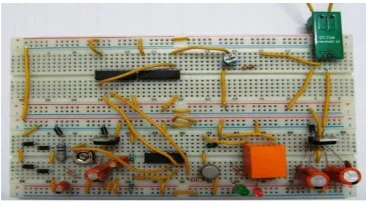
After setting the current sensor, the circuit was tested several times to see that, the circuit is operated in both under voltage and over current conditions or not. Figure-5.- shows the total circuit of the device which includes transistor, relay, diode, AND & NOT gates, current sensor, comparator (LM324),LED etc.
Figure-5: The total circuit of the device
B.Testing
There are two types of test carried out on the developed device. They are manual test and calibration.
1) Manual Test
The purpose of the manual test is to verify the functionality of the comparator (LM324).In this test the supply voltage is reduced from its normal value and check the relay trips or not.
2) Calibration of potentiometer
The potentiometer was adjusted to divide down the voltage to a safe value. Also, as the input mains supply voltage is varied using a variac, the potentiometer was used to set the threshold for tripping of the relay. Immediately the output set voltage is reached, the load received mains supply without any problem.
The completed device was tested with house appliances such as television, DVD players, refrigerator, and single phase surface pump; and the performance was satisfactory. The condition for output triggering was stable after several testing. The output set voltage of 200-240 volts was maintained throughout the test period.
VI.RESULTS AND DISCUSION
In figure-6, Output voltage to relay driver vs. voltage being supplied to the motor is shown. Here, we can see that when the supply voltage is below or equal to 200 volts, the voltage to relay driver is very low (almost zero), which cuts off the supply.
In figure-7, the relation of supply voltage and output voltage at load terminals is shown.
Figure 7 -Output Voltage Supplied To Load vs. Supply Voltage
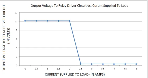
In figure-8, the relation between current to the load and voltage supplied to relay driver is shown. We can see that when the current to the load terminal is more than 2.5A, the voltage to relay driver is very low (almost zero), which cuts off the supply.
Figure 8 -Output Voltage To Relay Driver Circuit vs. Current Supplied To Load
VII.CONCLUSION
The aim of designing and constructing a low under-voltage and over-current protective device was achieved in this work. The device supplies power to the connected load whenever the input supply is within the required pre-set voltage, thereby protecting the output connected loads from un-necessary damages. The device isfound to be economical, easier to maintain and repair. The device cost about INR 500 to produce.
VIII.FUTURE WORKS
1. Overvoltage Protection-Just as we have set a reference voltage for lower voltage limit and the variable voltage resembles with the input voltage, similarly we could have set up the reference as upper voltage limit and the input as lower voltage limit, comparing it by a comparator and connecting it with a relay. Thus we could have Overvoltage protection in the same circuit.
2. Microcontroller Based Protection-We could use a micro-controller like PIC16F877A in conjunction with a liquid crystal display which can control the circuit tripping more accurately and also can give out information about it. Moreover, it would increase the overall sophistication of the protection circuit.
3. Alarming circuit-In this circuit as alarm, we have provided 2 light emitting diodes. Though, some more advanced alarming can be done using a separate circuit which will generate an audio-visual warning signal, thus alerting everyone in the motors vicinity.
4. Protection of multiphase motors-Though we have created a protection circuit for only a single phase motor, 3 phase motor protection circuit could also be created. In those circuit, some schemes should also be considered i.e. single phasing.
REFERENCES
[1]J.B.GUPTA (2014) A COURSE IN POWER SYSTEMS (KATSON BOOKS), Part-III: Switchgear and Protection, Chapter-9, 169-171. [2] M.D.SINGH, K.B.KHANCHANDANI (2nd Edition) Power Electronics [McGraw Hill Education (India) Private Limited], chapter 6: Phase control converters, 329-346.
[3] ROBERT L. BOYLESTAD, LOUIS NASHELSKY (2015) Electronic Devices and Circuit Theory (English) 11th Edition (PEARSON), Chapter-10: Operational Amplifiers, Chapter-11: Op - Amp Applications, Chapter-1: Semiconductor Diode (7-16), Chapter3: Bipolar Junction Transistors (132-164).
[4] J.B.GUPTA (2014) Theory & Performance of ELECTRICAL MACHINES, PART-III, Transformers (1-91).
[5] S.SALIVAHANAN & S.ARIVAZHAGAN (FOURTH EDITION), DIGITAL CIRCUITS AND DESIGN, CHAPTER-3: Logic Gates (84-87) [6] Bayindir R., Sefa I., Cola I., and Bektas A. “Fault Detection and Load Protection Using Sensors”, IEEE Transactions on Energy Conversion, Vol. 23, Issue 3, pp. 734– 741, 2008.
[7] Ponnle A. A, Omojoyegbe M. O. “Development of a Low Cost Microcontroller Based Under and Over Voltage Protection Device”, IEEEVolume No.3 Issue No.9, pp: 1225-1229, 2014.
[8] Girish Chandra Thakur, Kumar Shantanu Kaushal, Manish Ranjan, sandipkumar gupta. , “Implementationof Single Phasing, Over Voltage, Under Voltage, Protection of Three Phase Appliances without Using Microcontroller”, Int. Journal of Engineering Research and Applications, ISSN : 2248-9622, Vol. 5, Issue 5, ( Part -6), pp.110-115, May 2015.
[9] Manish Paul, Barnali Talukdar and Banani Baishya , “ Simulation of Overvoltage and Undervoltage Protection in PSIM”, International Journal of Engineering Research & Technology (IJERT) ISSN: 2278-0181, pp.1005-1008, Vol. 3 Issue 11, November-2014.