ISSN (Print) : 2320 – 3765 ISSN (Online): 2278 – 8875
I
nternational
J
ournal of
A
dvanced
R
esearch in
E
lectrical,
E
lectronics and
I
nstrumentation
E
ngineering
(An ISO 3297: 2007 Certified Organization)
Website: www.ijareeie.com
Vol. 6, Issue 3, March 2017
PLC Based Railway Interlocking System
Monitored by SCADA
Thokchom Bandana Devi1, Dr. Namit Gupta2 , Jitendra Sharma3
P.G. Scholar, persuing M.Tech in Digital Instrumentation, Department of Electronics and Instrumentation Engineering,
Shri Vaishnav Institute of Technology and Science, Indore, Madhya Pradesh, India 1
Professor and Head, Department of Electronics and Instrumentation Engineering, Shri Vaishnav Institute of
Technology and Science, Indore, Madhya Pradesh, India 2
Senior Automation Engineer, Instrumentation and Control Solution, Indore, Madhya Pradesh, India3
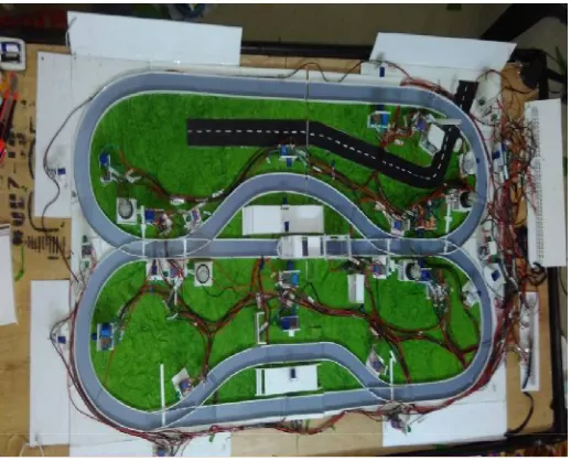
ABSTRACT: In railway signaling system, Interlocking refers to the arrangement of junctions or crossings in such a way so as to avoid the collision and derailment of trains. The main purpose of interlocking is to check a route request and provide a suitable one which will not cause any collision. In this paper, the main concern is about PLC based Interlocking System, where the whole operation will be automated and it is considered as the main advantage. The same ladder logic programming can be applied to another circulation track. PLC has become the most common choice for manufacturing controls. The monitoring of the interlocking process has been done through SCADA software and hence it makes it easier to visualize the whole working model. Another advantage of using SCADA is that if the working of any section has been disrupted in between than it can easily be identified and checked for further corrections.
KEYWORDS: Railway Interlocking, Automation, PLC, SCADA.
I. INTRODUCTION
ISSN (Print) : 2320 – 3765 ISSN (Online): 2278 – 8875
I
nternational
J
ournal of
A
dvanced
R
esearch in
E
lectrical,
E
lectronics and
I
nstrumentation
E
ngineering
(An ISO 3297: 2007 Certified Organization)
Website: www.ijareeie.com
Vol. 6, Issue 3, March 2017
II. EXISTING SYSTEM
Initially mechanical interlocking was used which consisted of levers, pulleys, steel wire to control signals and channel iron to operate points. Locking between signals and signals, or signals and points were done using levers and a tappet system in the locking frame. Levers and the signaling equipment had direct mechanical connections. However, in this type of interlocking the area of control was limited. Then relay interlocking is introduced. In Indian Railways, the existing interlocking system is relay based interlocking system which is semi-automated.
Demerit: Relay based interlocking system was time consuming because if any alterations were required then the rewiring of panels and devices was to be done. This also means that the system is more prone to errors and is not 100 percent fail safe.
III. PROPOSED SYSTEM
In this paper a PLC based railway interlocking system which will be monitored by SCADA is proposed. The advantage of using PLC is that a single programmable logic controller can easily run many machines. Also the problem of error correction will become simplified, unlike the old days of relay interlocking where if any alterations were required then the rewiring of panels and devices was very time consuming. SCADA systems will be helpful in collecting and storing information for reporting, troubleshooting and maintenance indications and much more. So PLC and SCADA based railway interlocking system will prove to be a more efficient and less error prone system. For the communication between PLC and computer RS-232 cable has been used.
ISSN (Print) : 2320 – 3765 ISSN (Online): 2278 – 8875
I
nternational
J
ournal of
A
dvanced
R
esearch in
E
lectrical,
E
lectronics and
I
nstrumentation
E
ngineering
(An ISO 3297: 2007 Certified Organization)
Website: www.ijareeie.com
Vol. 6, Issue 3, March 2017
IV. PROGRAMMABLE LOGIC CONTROLLER
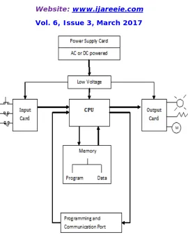
Allen Bradley PLC (Micrologix 1000) has been used for controlling input and output of the model. A same program has been constantly executed by PLC, which can receive input from and give output to a large number of external devices. So for railways, where the controlling of a lot of wayside elements is needed, PLCs make a good match. Interlocking logic forms the core of PLC interlocking system, which runs on a PLC hardware. Relays are connected to each and every input and output of the PLC system. These relays helps to switch the input signal for PLC on identifying some external signal or based on the output of the PLC they switch the external signals. PLC interlocking can switch to different voltages and more powerful currents by using the relays. Allen Bradley PLC (Micrologix 1000) comes in many configurations differing in the number of inputs and outputs, type of power supply and the type of I/O interfaces. The PLC used by us has 32 I/O and 24 VDC power supply. The software used in Allen Bradley PLC programming is RSLogix Micro. This software can run only in Windows Xp, so VMWare Workstation software allows us to run the RSLogix software even if we don’t have Windows Xp. So it is an alternate method to run Windows Xp.
ISSN (Print) : 2320 – 3765 ISSN (Online): 2278 – 8875
I
nternational
J
ournal of
A
dvanced
R
esearch in
E
lectrical,
E
lectronics and
I
nstrumentation
E
ngineering
(An ISO 3297: 2007 Certified Organization)
Website: www.ijareeie.com
Vol. 6, Issue 3, March 2017
Figure 3: PLC Architecture
V. SCADA
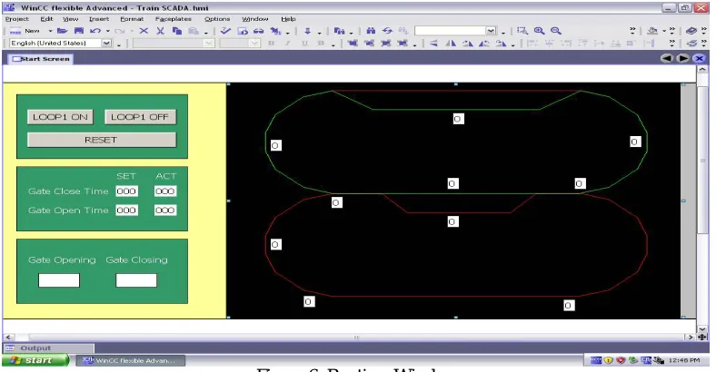
It is an industrial automation control system used for monitoring, gathering and processing data. In SCADA architectures, there are four distinct levels that is field instrumentation, PLC, communication network and SCADA host. The information from manual inputs or sensors is sent to PLCs which is further sent to the computer with SCADA software. SIMATIC WinCC is the SCADA software used in the project. It analyzes and display the data obtained from the field location and helps the operator from unnecessarily visiting the remote location. Since the graphical representation of the field location can be easily seen on the computer screen with the help of SCADA, it makes the monitoring task visual and easier. There are two modes in SCADA, these are Development Mode / Window maker and Runtime Mode. In Development Mode programming is done and in Runtime Mode the running status can be seen.
ISSN (Print) : 2320 – 3765 ISSN (Online): 2278 – 8875
I
nternational
J
ournal of
A
dvanced
R
esearch in
E
lectrical,
E
lectronics and
I
nstrumentation
E
ngineering
(An ISO 3297: 2007 Certified Organization)
Website: www.ijareeie.com
Vol. 6, Issue 3, March 2017
VI. RESULTS AND SIMULATION
Ladder logic is the main programming that has been used for PLC in which number of input are repeated whereas output cannot be repeat. But the output can be repeated as an input. The ladder logic resembles the relay logic to a large extent. A ladder logic program has been shown above in which the power is indicated on the vertical line on the left side basically known as hotrail. On the right hand side is the neutral rail. Between the hotrail and neutral rail there are two rungs and on each rung there are combination of inputs (to vertical lines) and outputs (coils). According to right combination of inputs (open or close) the power flows from hotrail through the inputs, to the outputs and finally to the
neutral rail. An input comes from the sensors and the outputs are given to signals and motor outside the PLC.
Figure 5: Ladder Logic Programming of PLC
The two loops are represented by Loop 1 and Loop 2 which are further divided into different sections. Each section has its own sensor which gives input to PLC informing about the presence of a train by giving a logic high signal for clear path or logic low signal for occupied path. The green coloured sections represent the clear path whereas the red coloured sections represent either occupied path or wait state.
ISSN (Print) : 2320 – 3765 ISSN (Online): 2278 – 8875
I
nternational
J
ournal of
A
dvanced
R
esearch in
E
lectrical,
E
lectronics and
I
nstrumentation
E
ngineering
(An ISO 3297: 2007 Certified Organization)
Website: www.ijareeie.com
Vol. 6, Issue 3, March 2017
VII. CONCLUSION
This paper presented a PLC based railway interlocking which is monitored by SCADA. These efforts have been made previously too but are still under exploration especially in India and have not been practically implemented so far. We made an effort to study it thoroughly and present a working model for the same. We have concluded that as compared to the existing relay based interlocking system used in Indian railways, PLC based interlocking system would make it much efficient because the whole controlling action would become automated. As it is clear from the number of railway accidents occurred so far and still occurring, a more efficient, accurate and fail safe system is needed. We have concluded that being the largest network and having a number of wayside equipments to be controlled at the same time, Indian railways is highly in need of a PLC based interlocking system.
REFERENCES
1) R.Gopinathan and B.Sivasankar, “PLC Based Railway Level Crossing Gate Control,” international journal of emerging technology in computer science & electronics (IJETCSE), ISSN:0976-1353, Volume 8, Issue 1- April 2014.
2) Y.Baba, A.Hiratsuka, E.Sasaki, O.Yamamoto and M.Miyamoto, “Radio-based Train Control System,” Hitachi Review, Volume 61, 2012. 3) T.ten Hoeve,“Model Based Testing of a PLC Based Interlocking System,” Master thesis, University of Twente.
4) Allen Bradley MicroLogix 1000, Architecture and Operation, module1.
5) O.Eris and I.Mutlu,“Design of Signal Control Structures Using Formal Methods for Railway Interlocking Systems,” 11th
Int.Conf.Control,Automation,Robotics and Vision, December 2010.
6) ‘Simulation of Relay Interlocking Systems’ by L.E.Eriksen and B.Pedersen, 2007. 7) Pramod P.Goel, “Indian Railway Signal Engineering,” Volume 4, January 2010.
8) T.Sudha and S.Suresh,“Railway Route Mapping Based on PLC and SCADA,” International Journal of Research in Engineering, Science and Technologies (IJRESTs), Volume 1, May 2015.
9) P.K.Kumar and B.S.ShivaShankara,“PLC Based Automatic Fault Detection of Railway Track and Accidence Avoidance System,” International Journal of Engineering Research and General Science, ISSN 2091-2730, Volume 3, Issue 2, March-April 2015.
10) N.Bhargav, A.Gupta, M.Khirwar, S.Yadav and V.Sahu,“Automatic Fault Detection of Railway Track System Based on PLC (ADOR TAST),” International Journal of Recent Research Aspects, ISSN : 2349-7688, Volume 3, Issue 1, March 2016.
11) ‘Automated Manufacturing Systems PLCs (Second Draft)’ by H.Jack.
12) ‘Supervisory Control and Data Acquisition (SCADA) System’, Technical Information Bulletin NCS TIB 04-1, National Communications System, October 2004.
13) M.Prabhakar and A.Ashok Babu,“Sensor Based Train Collision Identification and Avoidance Systems,” International Journal & Magazine of Engineering, Technology, Management and Research, ISSN : 2348-4845 , Volume 3, Issue 10, October 2016.
14) T.Dhanabalu, S.Sugumar, S.Suryaprakash and A.VijayAnand, “Sensor based identification system for Train Collision Avoidance,” IEEE sponsored 2nd International Conference on Innovations in Information Embedded and Communication Systems (ICIIECS), Volume 3, 2015. 15) M.Ganapathi and G.Priyanka, “Smart System for Train Crash Avoidance,” International Journal of Innovative Technologies, ISSN :
2321-8665,Volume 4, Issue 11, August 2016.
16) Naga Hema Kumari.V and China Appala Naidu.R, “Train Collision Avoidance by Using Sensors,” International Journal of Advanced Research in Computer Science and Software Engineering, Volume 6, Issue 6, June 2016.
17) Wikipedia - https://en.wikipedia.org/