1142 | P a g e
Utilization of Waste Heat from an Air
Conditioning System
Hrishikesh Kambli
1, Devyani Padwal
2, Yogesh Kudale
3Department of Mechanical Engineering, MCT’s Rajiv Gandhi Institute of Technology,
Mumbai University, Mumbai, (India)
ABSTRACT
The energy demand of the world is increasing significantly.High grade energy can be completely converted into
other form while the same cannot be done for the low-grade energy. One type of low grade energy is Heat
energy. Thus,attempts should be taken to utilize this heat energy through waste heat retrieval systems. This
paper concentrates on use of waste heat from Air Conditioning Unit, to heat water thus reducing the
consumption of any form of heat and electrical energy. The water is heated in a storage tank comprising of a
copper tube network in it. The waste heat utilized is the heat rejected by the condenser. When this heated water
reaches the calculated temperature, it is then used for the required purpose. The result of the paper shows the
amount of electricity saved while heating water for industrial purposes.
Keywords: Air Conditioning Unit, Copper Tube Network, Heat Energy, Saves Electricity,
Waste Heat Recovery.
I
INTRODUCTION
Energy is the preliminary requirement in day to day life. Energy is categorized as Renewable Energy and Non-Renewable Energy. Non-Renewable energy is energy that is acquired from renewable resources, which are replenished in a natural manner whilerenewable energy does not renew itself at an adequaterate. Thus, non-renewable energy are finite resources which will deplete with time.
Energy conservation is the exercise of lessening the amount of energy used, this can be done either by using energy efficaciously or deducting the quantity of amenities used or using waste energy. One such type of waste energy is heat energy. Waste heat is the energy generated by many refrigeration operation and this energy is dissipated to the surrounding even when it can still be utilized for some advantageous and lucrative purposes. If efficient steps are taken to utilize this waste heat energy, the amount of actual heat energy required for various purposes will automatically reduce.
This paper mainly dealswith heating of water for several applications by the use of heat dissipated by condenser of an Air conditioning unit. Waste heat which is rejected by the condenser in condensation process is at higher temperature than that of atmospheric temperature which is further transferred through a copper tube winding and used for heating purpose.This solution uses the heat efficaciouslyfor some other beneficial work.
The concept of hot water production system using an air conditioning unit is evaluated, divided and organized into seven sub-sections. The first subsection deals with existing theories and models discussed by other researchers related to the system. This sub-section is followed by the second section which explains the construction of the hot water production system with a relevant diagram. The third section throws light on the working of this system followed by the detailed mathematical and thermodynamic calculations which forms the fourth section. The fifth section mentions the results and graphs regarding the calculations done in the previous section. The sixth section deals with the future scope and advantages of the system. The last section is the conclusion which illuminates the practicality of the system and the amount of electricity saved.
II
EXISTING
SYSTEMS
Wasteheat recovery from air conditioners by use of heat absorption pump by SohanSarangi[1].
The paper states that the waste heat exhausted by Air-Conditioners can supplysatisfactory heat energy to provide warm water to boilers for heating and other purposes. If the system uses absorption heat pump, the low-qualityleft-over heatcan be transformed into high temperature heat which can be utilized for industrial purposes.
Efficient usage of waste heat from air conditioner by M. Joseph Stalin, S. Mathana Krishnan, G. Vinoth
Kumar[2]
This paper explains the conceptual analysis of creation of hot water and minimizing usage of LPG gas by means of air conditioner waste heat. For this water-cooled condenser is used and the water is circulated by the pump until the desired temperature is acquired. The heated water is accumulated in an insulated tank for further use.
Waste Heat Recovery through Air Conditioning System by R. B. Lokapure, J. D. Joshi[3].
In this paper, the main criteria areenergy conservation by using technique of gaining waste heat from Air-conditioning system and increasing Coefficient of Performance (COP). The target of improving COP was up to 20%, but in this case, only13%was achieved.
Heat Recovery from Vapor Compression Air Conditioning by Michael Guglielmone, Fred Scheideman,
Yogesh Magar[4].
This paper is proposed to introduce the idea of heat retrieval from vapor compression air conditioning systems. Other adjustments on this theme are possible, such as transferring the heat to a process fluid like ethylene glycol and using the heat in industrialprocesses instead of potable water heating.
III
DESCRIPTION
1144 | P a g e undergoes a phase change[5].In a vapor compression cycle, the cooling is gained as the refrigerant evaporates at low temperatures. While evaporation, it gains heat from the cold body and this heat is used as its latent heat for transforming it from the liquid to vapor form. In condensing, this heat is dissipated to an external body, thus generating a cooling effect in the working fluid[6].
This refrigeration arrangement thus worksas a latent heat pump.The system pumps its latent heat from the cold body and transmits it to the exterior hot body. These kinds of systemsrequire mechanical energy to run the compressor. Thus, these systems are termed as mechanical refrigeration systems[5]. Vapor compression refrigeration systems are available for relief as well as many processes with the refrigeration sizes reaching upto few megawatts.
The main setback of this system is that a large amount of waste heat is dumped into the surrounding. This heat causes rise in global average temperature, thus leading to many environmental problems[7].
This heat can be extensively used for many purposes. Some industries like food and beverage, textile, chemical and pharmaceutical require hot water for carrying their regular process. Even hospitals are in a need of efficient hot water system.
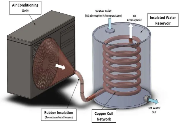
Fig 1: Waste Heat Recovery Setup
Thus, an idea has surfaced that can solve both the problems as well as save energy. By implementation of this waste heat recovery system (Fig 1) can scale back the typical electricity consumption.
The heat require for this system is acquired from the condenser of an air conditioning unit. The system uses 1TR air conditioning unit and the heat is rejected from the condenser unit in the form of hot air.
The coil and the condenser are connected by a copper pipe with rubber insulation. The rubber insulation is used to avoid the loss of heat energy from the copper pipe to the surrounding.The diameter of pipe carrying this hot air is ½ inch according to the standardsavailable.
A sensor is attached at the mid length of the copper coil to indicate that the pipe is half filled with air. This copper tube is placed inside an insulated water tank. This insulated water tank has a rubber insulation on its outer periphery to avoid heat loss.A thermostat is attached on the inner wall of the tank for recording the temperature of water. The tank has one inlet and one outlet for water flow. Inlet valve and outlet valve are at inlet and outlet position respectively. The inlet valve is controlled i.e. it will be opened by the sensor placed in the copper tube while the outlet valve will be controlled by the thermostat placed on the inner wall of the tank. These components together form a waste heat recovery system which uses the waste heat from an air conditioning unit and reduces the consumption of energy which is required for production of hot water.
IV
WORKING
The system works on the principle of using waste heat energy from condenser of an air conditioning unit. An air conditioner mainly consists of four parts, compressor, condenser, expansion valve and evaporator coil and works on the principle of vapor compression cycle [6]. The low pressure low temperature air enters into the compressors and gets transformed into high pressure high temperature air. Further this high pressure high temperature air goes to the condenser coils where it condenses and transforms to high pressure high temperature liquid. This liquid when enters the expansion valve, it undergoes throttling process. In throttling process, there is an abrupt reduction of temperature and pressure of liquid due to which it gets converted into liquid and flash gas [8]. This mixture then enters into the evaporator coil which helps cooling the air that is to be transmitted in the room and the cycle repeats.
1146 | P a g e The actual vapor compression cycle which is used in air conditioning system is different from the theoretical cycle in various ways. Usually the liquid refrigerant enters the expansion valve after sub-cooling, and generally superheated gas leaves the evaporator a few degrees before it enters the compressor [8].
Fig 3: Actual vaporcompression cycle (T-s diagram)
[5].
The actual vapor compression cycle on T-s diagram is as shown above. The various processes are discussed as follows:
Process 1-2-3:The progress of refrigerant through the evaporator is shown by this process, with 1-2 indicating gain of latent heat of vaporization, and 2-3, the gain of superheat before entrance to compressor. Both of these processes approach very similar to the constant pressure conditions [5].
Process 3-4-5-6-7-8:This path represents the passage of the vapor refrigerant from entrance to the discharge of the compressor. Path 3-4 represents the throttling action that occurs during passage through the suction valves, and path 7-8 represents the throttling during passage through exhaust valves. Both of these actions are accompanied by an entropy increase and a slight drop in temperature. Compression of the refrigerant happens along route 5-6, which is truly neither isentropic nor polytropic. The heat transfers indicated by path 4-5 and 6-7 occur essentially at constant pressure [5].
Process 8-9-10-11: This process denotes the way of refrigerant through the condenser with 8-9 representing removal of superheat, 9-10 the subtraction of latent heat, and 10-11 removal of warmth of liquid or sub-cooling[5].
Process 11-1: This processdenotes the passage of the refrigerant through the expansion valve [5].
The air conditioning unit described aboveuses an air-cooled condenser. The AC condenser provides with the supply of heated air. The heated air fromthiscondensergoes into a copper cone which is connected to the copper pipe.
The copper cone has larger area on its one end thus it will collect the maximum amount of waste air released from the condenser and direct the flow into the copper pipe. Also, the cone will increase the velocity of the air slightly due to reduction in cross section area thus aiding the flow of air. The copper cone and pipe have a rubber insulation so that there is no loss of heat energy.
The sensor which is attached inside the copper coil indicates that the coil is half filled with hot air.
The water tank consists of an inlet to which a valve is attached through which the water enters at room temperature. This inlet valve will open only when it receives a signal from the sensor placed in the pipe. This process is done to ensure that the whole coil is filled with hot air and the water in the tank is heated throughout. When the heated air is passing through the coil, heat transfer takes place. This leads to increase in temperature of water. The water tank being insulated from outside reduces heat transfer to the surrounding by a greater amount. A thermostat is mounted on the surface of the water tank which measures the temperature of water and the water is heated until the maximum stable temperature is attained.
When the water attains the calculated temperature, the outlet valve has to open. This outlet valve is being controlled by the thermostat which is measuring the temperature of the water. When a signal is received, the outlet valve will open to allow the flow of water.
Many industries require hot water in the range of 30-80ºC. Also, hospitals require hot water for processes like cleaning, sterilizing, bathing, etc. In a hospital 9-10% of total water requirement is of hot water which is produced by electrical energy or solar energy. Also, the hospitals use air conditioning units on a large scale. Therefore, this system can be extensively used in hospitals. Thus, this system helps in saving a large amount of electricity required to heat water.
Many of the industries require hot water in the range of 30-80ºC. Also, hospitals require hot water for processes like cleaning, sterilizing, bathing, etc. In a hospital 9-10% of total water requirement is of hot water which is produced by electrical energy or solar energy. Also, the hospitals use air conditioning units on a large scale. Therefore, this system can be extensively used in hospitals. Thus, this system helps in saving a large amount of electricity required to heat water.
V
CALCULATIONS
Case 1)
When Air Conditioning unit operates at 30ºC i.e.at extreme temperature, the waste heat recovery arrangement can heat the water near 50ºC.
Heating of water is a classic thermodynamics problem and has the following formula: Q = m x Cp x dT
Where,
Q = amount of heat (kJ) Cp = specific heat (kJ/kgK) m = mass (kg)
dT = temperature difference between hot and cold side (K)
For heating 25 liters of water from 25ºC to 50ºC Q1= m Cp dT
= 25x4.187x(50-25)
1148 | P a g e For heating 25 liters of water from 25ºC to 90ºC
Q2 = m Cp dT
= 25x4.187x(90-25)
= 6803.875 kJ
Thus, saving in the energy for heating water from 25ºC to 90ºC is given by, Q = Q2- Q1
= 6803.875-2616.875
= 4187 kJ
Calculation for electricity unit is given by [9]: Units=
Consider the water requirement to be 25lts of hot water per day and preferred temperature of water is 90ºC. Let the inlet water temperature be 25ºC.
Then the best electricity units for water heating requirement is: (25 x (90-25) x4)/3412 = 1.95 units per 25 liters.
By implementation of waste heat recovery system, we are able to accomplish temperature upto50ºC.Now if the industry requires the water at 90ºC so they wouldhave to start heating the water that is already reached at 50ºC. Hence input temperature becomes 50ºC and required temperature is 80ºC. Then units for water heating requirement is calculated as:
25 x (90-50) x 4/3412 = 1.2 units per 25 liters. Hence saving in units =1.95-1.2
=0.75 Units
Cost per unit electricity=Rs 5.75 Hence,
Total saving of cost for heating 25 liter of water, up to 90ºC =0.75 x 5.75 = Rs. 4.3125.
Therefore, in a month (assuming 30 days) total saving of cost = 4.3125x30 = Rs. 129.375
And in 1-year total saving of cost for 25 liters of water = 129.375x12 = Rs.1552.5.
Case 2)
When Air Conditioning unit operates at 22ºC-23ºC i.e.at intermediate temperature, the waste heat recovery system can heat the water up to 55ºC
For heating 25 liters of water from 25ºC to 55ºC Q1= m Cp dT
= 25x4.187x(55-25)
= 3140.25 kJ
= 25x4.187x(90-25)
= 6803.875 kJ
Thus, saving in the energy for heating water from 25ºC to 90ºC is given by, Q = Q2- Q1
= 6803.875-3140.25
= 3663.625 kJ
Calculation for electricity unit is given by [9]: Units=
Consider the water requirement to be 25lts of hot water per day and preferred temperature of water is 80ºC. Let the inlet water temperature be 25ºC.
Then the best electricity units for water heating requirement is: (25 x (90-25) x 4)/3412 = 1.95 units per 25 liters.
By implementation of waste heat recovery system, we are able to accomplish temperature upto55ºC.Now if the industry requires the water at 80ºC so they wouldhave to start heating the water that is already reached at 55ºC. Hence input temperature becomes 55ºC and required temperature is 90ºC. Then units for water heating requirement is calculated as:
(25 x (90-55) x 4)/3412 = 1.05 units per 25 liters. Hence saving in units=1.95-1.05
=0.9Units
Cost per unit electricity=Rs 5.75 Hence,
Total saving of cost for heating 25 liter of water, up to 90ºC= 0.9 x 5.75 = Rs. 5.175.
Therefore, in a month (assuming 30 days) total saving of cost = 5.175 x 30 = Rs. 155.25
And in 1-year total saving of cost for 25 liters of water = 155.25 x 12 = Rs.1863.
Case 3)
When Air Conditioning unit operates at 16ºC -17ºC i.e.at minimum temperature, the waste heat recovery system can heat the water up to 60ºC.
For heating 25 liters of water from 25ºC to 60ºC Q1 = m Cp dT
= 25x4.187x(60-25)
= 3663.625 kJ
For heating 25 liters of water from 25ºC to 90ºC Q2 = m Cp dT
= 25x4.187x(90-25)
= 6803.875 kJ
1150 | P a g e Q = Q2- Q1
= 6803.875-3663.625
= 3140.25 kJ
Calculation for electricity unit is given by [9]: Units=
Consider the water requirement to be 25lts of hot water per day and preferred temperature of water is 80ºC. Let the inlet water temperature be 25ºC.
Then the best electricity units for water heating requirement is: (25 x (90-25) x 4)/3412 = 1.95 units per 25 liters.
By implementation of waste heat recovery system, we are able to accomplish temperature up to60ºC.Now if the industry requires the water at 80ºC so they wouldhave to start heating the water that is already reached at 60ºC. Hence input temperature becomes 60ºC and required temperature is 80ºC. Then units for water heating requirement is calculated as:
(25 x (90-60) x 4)/3412 = 0.9 units per 25 liters. Hence saving in units = 1.95-0.9
=1.05 Units
Cost per unit electricity=Rs 5.75 Hence,
Total saving of cost for heating 25 liter of water, up to 90ºC = 1.05 x 5.75 = Rs. 6.0375.
Therefore, in a month (assuming 30 days) total saving of cost = 6.0375 x 30 = Rs. 181.125
And in 1-year total saving of cost for 25 liters of water = 181.125 x 12 = Rs.2173.5.
Hence from above three cases it can be concluded that when Air Conditioning unit operates at 16-17ºC i.e. at lowest temperature waste heat retrieval system is extraadvantageous.
VI
RESULTS
A 1TR air conditioning unit is used to run the systemwhich works for 8 hours per day maintaining 18ºC room temperature. Results of our system are explained with the help of a graph which is a temperature versus time graph. Now the water entering the system is 25 liters and will be approximately at 25ºCi.e. at atmospheric temperature.
Graph 1: Temperature vs Time
This system provides water at 55ºC but if the industry requires water at 90ºC then the temperature is to be increased by only 35ºC. Thus, this system will save electricity because the initial 55ºCis attained using waste heat form the air conditioning unit.
It is seen that 1.95 units is required to heat25 liters of water from 25ºC to 90ºC. But due to this system a temperature of 55ºC is already attained thus only 1.05 units of electricity is required to heat the water. Hence the electricity saved for every 25 liters of water is 0.9 units.
VII
FUTURE
SCOPE
As our global temperature is increasing day by day it is not advisable to dump the heat generated from air conditioning units into the surrounding. Also, the water heating units consume a large amount of energy that can be saved by using the waste hear recovery system. Thus, this system targets two problems in one go.
The system is quite efficient for heating the water up to the temperature of 55ºC. But in future the size of the copper tube can be changed to increasing the heat transfer rates. Also, fins can be added on the copper coils which will increase the heat transfer rates because the surface area in contact with water increases.
VIII
CONCLUSION
From the above experimental analysis, it is seen that if this hot water system uses the heat energy from a condenser of an air conditioning unit maintaining room temperature between 16ºC-18ºC, it will save approximately 0.9 units of electricity for heating 25 liters of water up to 90ºC. This system not only saves cost for heating water but also avoids the unwanted heat from being dumped into the surroundings. If the system is incorporated in various industries, it will save a large amount of electricity.
REFERENCES
[1]. Sohan Sarangi, “Waste heat recovery from air conditioners by use of heat absorption pump “International Journal of Scientific & Engineering Research, Volume 6, Issue 7, July-2015 ISSN: 2229-5518
1152 | P a g e [3]. R. B. Lokapure, J. D. Joshi, “Waste Heat Recovery through Air Conditioning System”International
Journal of Engineering Research and Development e-ISSN: 2278-067X, p-ISSN: 2278-800X, Volume 5,
Issue 3 (December 2012)
[4]. Michael Guglielmone, Fred Scheideman, Yogesh Magar “Heat Recovery from Vapor Compression Air ConditioningA Brief Introduction”, White Paper, Turbotec, 2008.
[5]. B. Naveen, K. Balasubramanian, M. Yaswanth, A. V. Arun Kumar, U. Sastha Kumar, “Waste Heat Recovery in R & AC Systems”, International Journal of Science and Research (IJSR) ISSN (Online): 2319-7064.
[6]. Rex Miller, Mark R. Miller, “Air Conditioning and Refrigeration”, 2006
[7]. R. K. Rajput, “Engineering Thermodynamics Third Edition Si Units Version”, 2007 [8]. “Refrigeration and Air Conditioning”, IIT Kharahpur, 2008
![Figure 2: IdealVapor Compression Cycle [5].](https://thumb-us.123doks.com/thumbv2/123dok_us/7779905.1284567/4.595.130.471.494.727/figure-idealvapor-compression-cycle.webp)
![Fig 3: Actual vaporcompression cycle (T-s diagram) [5].](https://thumb-us.123doks.com/thumbv2/123dok_us/7779905.1284567/5.595.176.418.155.321/fig-actual-vaporcompression-cycle-diagram.webp)
