Automatic Railway Gate Controller with High
Speed Alerting System
Vikash Kumar
1, Prajit Paul
2, Nishant kumar
1, Pratik kumar Sinha
1, Sumant Kumar Mahato
1B. Tech Student, Dept. of ECE, Asansol Engineering College, Asansol, West Bengal, India
1Assistant professor, Dept. of ECE, Asansol Engineering College, Asansol, West Bengal, India 2
ABSTRACT: The aim of the paper is to avoid the railway accidents happening at unattended railway gates by using ATMEGA_16 microcontroller, if implemented in spirit. The model of railway track controller is designed by using four laser light sources as transmitters and four LDR as receivers; two pair of transmitters and receivers are fixed at upside (from where the train comes) at a level higher than a human being in exact alignment and similarly the other pair is fixed at down side of the train direction. The collision of two trains due to the same track also can be happened. This model is implemented using sensor technique. We placed the sensors at a certain distance from the gate detects the approaching train and accordingly controls the operation of the gate. Also an indicator light has been provided to alert the motorists about the approaching train.
KEYWORDS: Microcontroller, IR LED, Sensor, Anti collision device, track switching.
I. INTRODUCTION
Now a days, India is the country which having world’s largest railway network. Over hundreds of railways running on track every day. As we know that it is definitely impossible to stop the running train at immediate is some critical situation or emergency arises. Train accidents having serious consequence in terms of loss of human life, injury, damage to Railway property. Railway safety is a crucial aspect of rail operation over the world. Railways being the cheapest mode of transportation are preferred over all the other means. When we read newspaper, we come across many railway accidents occurring at unmanned railway crossings. This is mainly due to the carelessness in manual operations or lack of workers. This model deals with two things. Firstly, it deals with the reduction of time for which the gate is being kept closed. And secondly, to provide safety to the road users by reducing the accidents that usually occur due to carelessness of road users and at times errors made by the gatekeepers. To avoid the accidents, sensors placed at some distance from the gate detect the departure of the train. The signal about the departure is sent to the microcontroller, which in turn operates the motor and opens the gate. Thus, the time for which the gate is closed is less compared to the manually operated gates since the gate is closed depending upon the telephone call from the previous station. Also reliability is high, as it is not subjected to manual errors. The concept of the model is to control the railway gate using microcontroller or anti-collision technique.
II. OPERATION
Fig. 1: Railway Gate Controller
Initially transmitter is continuously transmitting the IR light which is made to fall on the receiver. When the train arrives it cuts the light falling on receiver. Let us assume the train is arriving from left to right, now when the train cuts the 1st sensor pair a counter is activated and when it crosses 2nd sensor pair the counter is stopped. This counter value gives the time period which is used to calculate the velocity of the train. The sensor2 output is sent to microcontroller which makes the relay activate which causes the gate to be closed. Now when the last carriage of the train cuts the sensor4 microcontroller de-activates the relay and gates are opened.
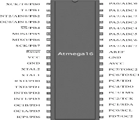
III.PIN DIAGRAM & CIRCUIT DIAGRAM
The ATmega16 is a low-power CMOS 8-bit microcontroller based on the AVR enhanced RISC architecture. By executing powerful instructions in a single clock cycle, the ATmega16 achieves throughputs approaching 1 MIPS per MHz allowing the system designed to optimize power consumption versus processing speed.
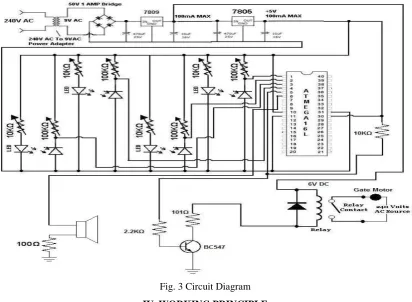
The operation of the circuit can be clearly explained as follows. Basically the circuit consists of four IR LED Photodiode pairs arranged on either side of the gate such that IR LED and photodiodes are on either side of the track as shown in the figure below
Initially transmitter is continuously transmitting the IR light which is made to fall on the receiver. When the train arrives it cuts the light falling on receiver. Let us assume the train is arriving from left to right, now when the train cuts the 1st sensor pair a counter is activated and when it crosses 2nd sensor pair the counter is stopped. This counter value gives the time period which is used to calculate the velocity of the train.
The sensor2 output is sent to microcontroller which makes the relay activate which causes the gate to be closed. Now when the last carriage of the train cuts the sensor4 microcontroller de-activates the relay and gates are opened.
Fig. 3 Circuit Diagram
IV. WORKING PRINCIPLE
Here the counter value is used to calculate the velocity of the train, which means that every wheel of the carriage cuts the sensor pair within small fraction of time based on its velocity. After the last carriage is passed there is no obstacle to the sensor pair within that fraction of time hence it knows that the train has left.
One more feature of this circuit is detecting a train accurately i.e, there may be a chance that some obstacle (for e.g some animal) may cut the sensor then in such a case the counter is made to run for certain period of time (this time period is set considering the possible lowest speed of train) if the obstacle does not cut the 2nd sensor before this predefined time then this obstacle is not considered as train and gates remain opened.
One more advantage of calculating the velocity of train is, if the speed of the train crosses a limit i.e, if it travel’s at an maximum speed then the passengers are alerted using a by activating a buzzer.
shown in the block diagram. The system displays the time taken by the train in crossing this distance from one pair to the other with a resolution of 0.01 second from which the speed of the vehicle can be calculated as follows:
Speed (km/h) = Distance/Time
This circuit has been designed considering the maximum permissible speed for trains as per the traffic rule. The microcontroller is used to process the inputs that are provided by the sensors and generate the desired outputs appropriately.
V. FLOW CHART
VI.CONCLUSION
This paper is suitably fulfilled the basic things such as avoidance of accidents inside the gate and the avoidable of a gatekeeper. It avoids the railway accidents and provides safety. We have seen little improvement in railway accidents. We also observed stronger safety records in certain areas and believe they are the result of constant efforts to improve safety. We demonstrate that it is possible to improve the overall safety of the railway system in India. We believe that success depends on both the railway industry and the regulator working together to achieve that common goal. The proposed system provide the means for real time inspection, review and data collection for the purpose of maintenance on the movable and fixed facilities for the guarantee of operation safety and maintenance efficiency as well as the safety appraisal decision-making system based on the share of safety data..
REFERENCES
[1] Natwar Singh, A complete reference of Micro Controllers. [2] Railways overview- a technical magazine.
[3] Muhammad Ali Mazidi, The 8051 microcontroller and embedded systems
[4] 8051 Microcontroller: An Applications Based Introduction by “David Calcutt, Frederick Cowan, and Hassan Parchizadeh” [5] ATMEGA16 microcontroller datasheet.
[6] Der Keil C51-Compiler by Michael Baldischweiler.
[7] San Francisco s “Advanced automatic warning signal system” in Proc. CERIE 2010, paper.