(Spine title: Nanomaterials for Fuel Cells) (Thesis format: Integrated-Article)
by
Shuhui Sun
Graduate Program in Mechanical and Materials Engineering
A thesis submitted in partial fulfillment of the requirements for the degree of
Doctor of Philosophy
The School of Graduate and Postdoctoral Studies The University of Western Ontario
London, Ontario, Canada
ii
CERTIFICATION OF EXAMINATION
Supervisor
______________________________ Dr. Xueliang (Andy) Sun
Supervisory Committee
______________________________ Dr. Robert Klassen
______________________________ Dr. Jun Yang
Examiners
______________________________ Dr. Zhongwei Chen
______________________________ Dr. Zhifeng Ding
______________________________ Dr. Robert Klassen
______________________________ Dr. Liying Jiang
The thesis by Shuhui Sun
entitled:
Development of Novel Nanomaterials for High-Performance and Low-Cost Fuel Cell Applications
is accepted in partial fulfillment of the requirements for the degree of
Doctor of Philosophy
iii
Proton exchange membrane fuel cells (PEMFCs) are promising energy converting technologies to generate electricity by mainly using hydrogen as a fuel, producing water as the only exhaust. However, short life-time and high cost of Pt catalyst are the main obstacles for the commercialization of PEMFCs. In the conventional carbon black supported platinum nanoparticle (NP) commercial catalyst, carbon supports are prone to oxidation and corrosion over time that results in Pt NPs migration, coalescence, even detaching from the catalyst support. In addition, Ostwald ripening of the Pt NPs could also occur due to their high surface energy and zero dimensional structural features. All these contribute to the degradation of fuel cell performance. This research aims at fabricating various advanced nanomaterials, including (1) Pt-based highly efficient nanocatalysts and (2) alternative nanostructured durable catalyst supports, to address the above-mentioned challenges in PEMFCs.
iv
To save more platinum, ultrathin Pt NWs with even smaller diameters of 2.5 nm (vs. 4 nm reported in our previous work) have been successfully synthesized when using N-doped CNTs as support. Direct evidence for the formation of ultrathin Pt NWs was provided by systematically investigating their growth process under TEM. Nitrogen doping in CNTs played a key role in the formation of ultrathin Pt nanowires.
In terms of low durability of PEM fuel cell catalysts, the corrosion of current commonly-used carbon black support materials have been identified to be the major contributor to the catalyst failure. One of the major challenges lies in the development of inexpensive, efficient, and highly durable alternative catalyst supports that possess high corrosion resistance, high conductivity and high surface area. In this work, a series of promising alternative nanostructured catalyst supports, including 0D Nb-doped TiO2 hollow nanospheres, 1D TiSix-NCNT nanostructures, and 2D graphene nanosheets, have been synthesized by various methods and used as catalyst supports. Pt nanoparticles were then deposited on these novel supports, showing enhanced catalytic activities and durabilities. Most interestingly, a new technique, atomic layer deposition (ALD), was used to uniformly deposit Pt nanoparticles, subnanometer clusters and single atoms on graphene nanosheets. Downsizing Pt nanoparticles to clusters or even single atoms could significantly increase their catalytic activity and is therefore highly desirable to maximize the efficiency.
In summary, the discoveries in this thesis contribute to applying various novel nanostructured materials to design highly active and stable electrocatalyst and durable catalyst support to develop high performance and low cost PEM fuel cells.
v
vi 1.
Title: A Highly Active and Durable Platinum Nanocatalyst for Proton Exchange Membrane Fuel Cells: Multiarmed Starlike Nanowire Single Crystal
Authors: Shuhui Sun, Gaixia Zhang, Dongsheng Geng, Yougui Chen, Ruying Li, Mei Cai, and Xueliang Sun
All the experimental and theoretical work was carried out by Shuhui Sun under the guidance of Dr. Xueliang Sun. The initial draft and the followed modifications of this manuscript were conducted by Shuhui Sun under the supervision of Dr. Xueliang Sun. The other coauthors contributed to the formation of the final version with discussion and related characterization. The final version of this manuscript has been published in Angewandte Chemie International Edition, 2011, 50, 422-426.
2.
Title: Direct Growth of Single-Crystal Pt Nanowires on Sn@CNT Nanocable: 3D Electrodes for Highly Active Electrocatalysts
Authors: Shuhui Sun, Gaixia Zhang, Dongsheng Geng, Yougui Chen, Ruying Li, Mei Cai, and Xueliang Sun
vii
Authors: Shuhui Sun, Gaixia Zhang, Yu Zhong, Hao Liu, Ruying Li, Xiaorong Zhou and Xueliang Sun
All the experimental and theoretical work was carried out by Shuhui Sun under the guidance of Dr. Xueliang Sun. The initial draft and the followed modifications of this manuscript were conducted by Shuhui Sun under the supervision of Dr. Xueliang Sun. The other coauthors contributed to the formation of the final version with discussion and related characterization. The final version of this manuscript has been published in Chemical Communications, 2009, 7048-7050.
4.
Title: Highly Stable and Active Pt/Nb-TiO2 Carbon-free Electrocatalyst for Proton Exchange Membrane Fuel cells
Authors: Shuhui Sun, Gaixia Zhang, Xueliang Sun, Mei Cai, and Martin Ruthkosky All the experimental and theoretical work was carried out by Shuhui Sun under the guidance of Dr. Mei Cai and Dr. Xueliang Sun. The initial draft and the followed modifications of this manuscript were conducted by Shuhui Sun under the supervision of Dr. Mei Cai and Dr. Xueliang Sun. The other coauthors contributed to the formation of the final version with discussion and related characterization. The final version of this manuscript was submitted for publishing.
5.
viii
All the experimental and theoretical work was carried out by Shuhui Sun under the guidance of Dr. Xueliang Sun. The initial draft and the followed modifications of this manuscript were conducted by Shuhui Sun under the supervision of Dr. Xueliang Sun. The other coauthors contributed to the formation of the final version with discussion and related characterization. The final version of this manuscript is to be submitted for publishing.
6.
Title: Enhanced Electrocatalytic Activity of Platinum Subnanoclusters on Graphene Prepared by Atomic Layer Deposition
Authors: Shuhui Sun, Xiangbo Meng, Gaixia Zhang, Dongsheng Geng, Ruying Li, Xueliang Sun, Nicolas Gauquelin, Gianluigi Botton, Siyu Ye, and Shanna Knights All the experimental and theoretical work was carried out by Shuhui Sun under the guidance of Dr. Xueliang Sun. The initial draft and the followed modifications of this manuscript were conducted by Shuhui Sun under the supervision of Dr. Xueliang Sun. The other coauthors contributed to the formation of the final version with discussion and related characterization. The final version of this manuscript is to be submitted for publishing.
7.
Title: Controlled Synthesis of Pt on Graphene Nanosheets by ALD and their Electrochemical Properties
ix
xi
This Ph.D. thesis work was carried out in Dr. Sun's Nanomaterials and Clean Energy Lab at the University of Western Ontario (UWO), Canada. After all those years, I've got quite a list of people who contributed in some way to this thesis, for which I would like to express thanks.
First and foremost, I would like to express my profound gratitude to my supervisor, Dr. Xueliang Sun, the Canada Research Chair in Nanomaterials for Clean Energy, a professor in the Department of Mechanical & Materials Engineering at UWO, for providing me with the opportunity to work under his guidance. I am very indebted to him for his patience, encouragement, insightful advice, and strong support in various ways. Without his extensive and comprehensive help, this thesis could not have been possible. His profound knowledge, rigorous attitude and enthusiasm in research also benefit me for life long. He is a role model for me as an excellent scientist.
I am very grateful to Mrs. Ruying (Kathy) Li, Dr. Sun’s wife and a research engineer in the group. She arranged everything perfect in our lab and made our lab a wonderful workplace. Besides teaching me a lot of skills on characterizing nanomaterials and experiments, Mrs. Li gave her kindness and generosity to my routine life as well. She was always ready to give me a hand whenever I was encountered with any problem. My wife and I are really appreciated Andy and Kathy’s always kind help and strong support. They might never know how important they are for us and we are indebted to them more than they know.
I am also very grateful to my former supervisors, Dr. Jean-Pol Dodelet (Canada industrial chair in electrocatalysis, INRS-EMT) and Dr. Edward Sacher (Ecole Polytechnique), for their always kind guidance, helpful suggestions and much help to my work and life, even after I left their groups.
xii
Chemistry at UWO), Zhongwei Chen (a professor in Chemical Engineering at University of Waterloo), and Dr. Robert Klassen for their careful examination, insightful suggestions, comments, and discussions.
I deeply appreciate to Dr. Mei Cai, project manager and technical lead in GM R&D Center (US), for her seven years strong support. Luckily, since 2004, I have been working on two projects collaborated with Dr. Cai and GM. In addition, many thanks to Dr. Cai for offering me the summer internship opportunity in her lab at GM and leading me working on diverse exciting projects. Particularly, I would also like to thank Dr. Cai for her strong support to my a series of successful prestigious scholarship applications.
I would like to express my acknowledgements to Dr. Siyu Ye at Ballard and Dr. Jiujun Zhang at National Research Council of Canada Institute for Fuel Cell Innovation, for their kind guidance and fruitful discussion on my work.
Many thanks to all my group members in Dr. Andy Sun’s group, Dr. Yong Zhang, Dr. Gaixia Zhang, Dr. Jiajun Wang, Mohhammad Norouzi Banis, Dr. Yougui Chen, Dr. Hao Liu, Yu Zhong, Dr. Yuhai Hu, Dr. Dongsheng Geng, Dr. Xifei Li, Dr. Xiangbo (Henry) Meng, Dr. Liang Li, Harmid Norouzi Banis, Yongliang Li, Dongniu Wang, Jinli Yang, Jian Liu, Dr. Mihnea Ioan Ionescu, Dr. Madhu Sudan Saha, and Dr. Ying Chen. It was a so much pleasure to work with so many nice people. Without their collaboration, generous help, and friendship, my project could not have been done so smoothly. I wish all of them good luck in the future.
xiii
I am grateful to the Natural Sciences and Engineering Research Council of Canada (NSERC), General Motors (GM) of Canada, Ballard Power Systems Inc., Canada Research Chair (CRC) Program, Canada Foundation for Innovation (CFI), Ontario Early Researcher Award and the University of Western Ontario for funding. I am also grateful to NSERC for granting me 3-year Alexander Graham Bell Canada Graduate Scholarship (NSERC CGS D).
Specially, I would like to express my sincere gratitude towards my parents and parents-in-law, for their understanding, support and encouragement, especially my heartiest thanks to them for their love and dedication to my babies. I would also like to thank my brother and sister-in-law, and my sister and brother-in-law on my wife’s side for their love and support as well.
Words fail me to express my appreciation to my wife, Gaixia Zhang, whose dedication, love and persistent confidence in me, has taken the load off my shoulder. I owe her for being unselfishly let her intelligence, passions, and ambitions collide with mine. It is my extraordinarily fortunate to take her hand and experience my life with her. I would also like to thank my two wonderful babies, Amy (Ziqi) and Kevin (Peining), who provide unending inspiration and happiness to our family.
xiv
CERTIFICATE OF EXAMINATION………..……….ii
ABSTRACT……….………..iii
CO-AUTHORSHIP ……….………vi
DEDICATION………x
ACKNOWLEDGEMENGTS……….xi
TABLE OF CONTENTS…………..………..…………xiv
LIST OF TABELS………xx
LIST OF FIGURES …………..………...…………..……….xxi
LIST OF APPENDICES.…….…………...……….xxx
LIST OF ABBREVIATIONS..………..……….xxxi
Chapter 1. Introduction…………..………1
1.1 Introductions to fuel cells……….1
1.1.1 Fundamentals of fuel cells………..………...…………1
1.1.2 Proton exchange membrane fuel cells (PEMFCs)……….………5
1.2 Challenges of PEMFCs………7
1.3 The solutions with nanomaterials……….8
1.3.1 Novel nanostructures of Pt catalyst……….………..………9
1.3.2 Nanostructured catalyst supports……….…..…..……10
1.4 Thesis objectives………11
1.5 Thesis organization……….…...…….14
References……….….……..19
Chapter 2. Experimental and Characterization Techniques…..………..……25
xv
2.1.2. Synthesis of Sn@CNT nanocable and N-doped CNT via chemical
vapor deposition (CVD) method……….………….25
2.1.3. Synthesis of Nb-TiO2 hollow spheres via sol-gel method……..….…27
2.1.4. Synthesis of TiSix-NCNT via CVD and sputter deposition………….28
2.1.5. Synthesis of graphene via chemical method………..………..28
2.1.6. Synthesis of Pt nanoparticles and single atoms via atomic layer deposition (ALD)………..………...29
2.2 Characterization techniques………...………32
2.2.1. Physical characterization (SEM, TEM, EDX, XPS, XRD)….………32
2.2.2. Electrochemical characterization……….………37
2.2.2.1. Cyclic voltammetry (CV)……….……37
2.2.2.2. Oxygen reduction reaction (ORR)……….39
2.2.2.3. Methanol oxidation reaction (MOR) and CO stripping…….39
2.2.2.4. Accelerated durability test (ADT)………...40
References……….……….…………..41
Chapter 3. A Highly Durable Platinum Nanocatalyst for Proton Exchange Membrane Fuel Cells: Multiarmed Starlike Nanowire Single Crystal……….………44
3.1 Introduction………46
3.2 Experimental………..………47
3.2.1 Synthesis of platinum nanowires...………..………47
3.2.2 Physical characterization...………..………47
3.2.3 Electrochemical characterization……….…………48
3.3 Results and discussion………49
3.4 Conclusions………..………..58
Acknowledgements………..58
xvi
Chapter 4. Direct Growth of Single Crystal Pt Nanowires on Sn@CNT
Nanocable: 3D Supports for Highly Active Electrocatalyst……66
4.1 Introduction………68
4.2 Experimental………..………69
4.2.1 Sn@CNT nanocables synthesis...………69
4.2.2 Growth of Pt nanowires on Sn@CNT/carbon paper and characterization...…………...70
4.2.3 Electrochemical measurements………70
4.3 Results and discussion………71
4.4 Conclusions………..……..84
Acknowledgements………..84
References………..………..86
Supporting Information……….………..91
Chapter 5. Ultrathin Single Crystal Pt Nanowires Grown on N-doped Carbon Nanotubes………..……….92
5.1 Introduction………94
5.2 Experimental………..……95
5.2.1 Synthesis of N-doped carbon nanotubes ……….………95
5.2.2 Growth of Pt nanowires on N-CNTs...………...95
5.2.3 Characterization ………..………95
5.3 Results and discussion………96
5.4 Conclusions………..102
Acknowledgements………..………..103
References………..104
xvii
6.1 Introduction………..…………114
6.2 Experimental………115
6.2.1 Chemicals………...………115
6.2.2 Preparation of Mesostructured Nb-TiO2 Support…………...………115
6.2.3 Preparation of PtNPs/Mesostructured Nb-TiO2 Composite…...……115
6.2.4 Physical Characterization………...………116
6.2.5 Electrode Preparation……….………116
6.2.6 Electrochemical measurements……….……….117
6.3 Results and discussion………..…………117
6.4 Conclusions………..126
Acknowledgements………..………..127
References………..128
Supporting Information………...……..132
Chapter 7. Pt/TiSix-NCNT Janus Nanostructures for Highly Stable and CO-Tolerant PEM Fuel Cell Electrocatalyst………133
7.1 Introduction………..…135
7.2 Experimental………136
7.2.1 Synthesis of TiSix-NCNT support………..………136
7.2.2 Synthesis of Pt NPs on TiSix-NCNT support……….…………137
7.2.3 Physical Characterization……….……..…137
7.2.4 Electrochemical measurements……….…….137
7.3 Results and discussion………..………138
7.4 Conclusions………..148
Acknowledgements………..………..148
References………..149
xviii
Methanol Oxidation……….……154
8.1 Introduction………..……157
8.2 Experimental………158
8.2.1 Preparation of graphene……….……158
8.2.2 ALD of Pt on graphene………..………158
8.2.3 Characterization ………159
8.2.4 Electrode Preparation……….………159
8.2.5 Electrochemical measurements……….……….160
8.3 Results and discussion………..………160
8.4 Conclusions………..170
Acknowledgements………..………..171
References………..172
Supporting Information………...………..176
Chapter 9. Controlled Synthesis of Pt on Graphene Nanosheets by ALD and their Electrochemical Properties………..………..178
9.1 Introduction………..………180
9.2 Experimental………182
9.2.1 Preparation of graphene……….………182
9.2.2 ALD Synthesis of Pt on graphene………..………182
9.2.3 Physical Characterization..……….………183
9.2.4 X-ray Absorption Spectroscopy………...………..184
9.2.5 Electrode Preparation……….………184
9.2.6 Electrochemical measurements………..………184
9.3 Results and discussion………..………185
9.4 Conclusions………..197
Acknowledgements………..………..197
xix
10.2. Future Perspectives……….….………207
APPENDICES.…….…………...………..……….210
xx
……….….…….…….…..Chapter 1……….….…….…………..
Table 1.1. Comparison of different types of fuel cells.……….……3
……….….…….…….…..Chapter 6……….….…….…………..
xxi
……….….…….…….…..Chapter 1……….….…….…………..
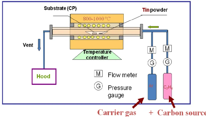
Figure 1.1. Schematic of CVD synthesis of Sn@CNT nanocables………...……2
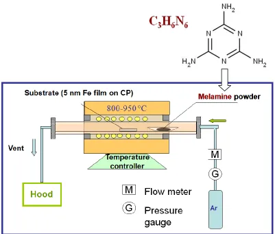
Figure 1.2. Schematic of CVD synthesis of N-CNTs………..………..6
Figure 1.3. Schematic diagram of an ALD process……….15
……….….…….…….…..Chapter 2……….….…….………….. Figure 2.1. Schematic of CVD synthesis of Sn@CNT nanocables….…………26
Figure 2.2. Schematic of CVD synthesis of N-CNTs………..27
Figure 2.3. Schematic diagram of an ALD process……….29
Figure 2.4. A screen snapshot on the LabVIEW program of the ALD system……….……….…..30
Figure 2.5. Experimental setup for ALD……….31
Figure 2.6. A photo of our SEM (Hitachi S-4800)………..33
Figure 2.7. A photo of our TEM (Philips CM10)………34
Figure 2.8. A photo of VG ESCALAB 220iXL XPS……….…….35
Figure 2.9. A photo of Bruker D8 Advance XRD………...……36 Figure 2.10. (a) diagram illustration of standard three-electrode cell; (b)
xxii
……….….…….…….…..Chapter 3……….….…….…………..
Figure 3.1. A) SEM and B) TEM image of carbon-supported multiarmed starlike Pt nanowire catalyst. ……….….…….……….…..….….….50 Figure 3.2. A) CV curves and B) hydroxy surface coverage (ΘOH) for Pt/C
(E-TEK, blue curve) and starlike PtNW/C (40 wt % Pt; red curve) catalysts. C) Polarization curves for ORR of Pt/C (E-TEK; blue curve) and starlike PtNW/C catalysts (red curve) in O2-saturated 0.5 M H2SO4 solution at room temperature (1600 rpm, sweep rate 10 mV s−1). D) Mass activity and specific activity at 0.9 V (vs. RHE) for the two catalysts. ……….….…….………..….…….52
xxiii
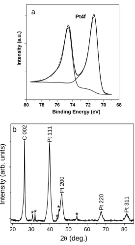
nanostar, indicating that the nanowire is single crystalline.……..…63 Figure SI-3.2. A typical X-ray diffraction pattern of carbon-supported star-like Pt nanowires, showing characteristic crystalline faces of Pt. ……...…64 Figure SI-3.3. TEM images of Pt/C (E-TEK) (A) before, and (B) after accelerated CV test; 40wt% PtNW/C (C) before, and (D) after accelerated CV test; supportless Pt NW (E) before, and (F) after accelerated CV test. ……….….…….……….….…….………..……65
……….….…….…………..Chapter 4………..…….…….….………..
xxiv
Potential scan rate 50 mV s−1.……….……….….….…79 Figure 4.7. Cyclic voltammograms for methanol oxidation (1 M methanol in 0.5 M H2SO4). Trace a) before growth of PtNWs; trace b) after growth of PtNWs on Sn@CNT; trace c) ETEK commercial catalyst of Pt nanoparticles on carbon black……….…….……….80 Figure 4.8. CVs of a) PtNW‒Sn@CNT/carbon paper 3D electrode and b) a commercial Pt/C electrode in the presence of CO in 0.5 M H2SO4 aqueous solution at room temperature. Potential scan rate: 50 mV s.−1 For both catalysts, a sharp peak appears during the first scan (solid line) and disappears in the subsequent scan (dash line)………....…82
Figure SI-4.1. TEM image of PtNW-Sn@CNT heterostructures…………....….…91
……….….…….…………..Chapter 5………..…….…….….………..
Figure 5.1. TEM images of N-CNTs before (A) and after (B) the growth of Pt NWs; TEM (C) and HRTEM (D) images of ultrathin Pt NWs….…96 Figure 5.2. Typical XPS spectra of N-CNTs before and after Pt deposition. (A) C1s, and (B) N1s……….….…….……….……98 Figure 5.3. EELS mapping of a pristine N-doped CNT: (A) bright field image; (B) carbon map; (C) nitrogen map……….….………….…..…….100 Figure 5.4. TEM images show the growth process of ultrathin Pt NWs on
xxv
into the graphitic structure……….….……….……107
Figure SI-5.2. SEM and TEM images of unsupported Pt nanowires which grew freely in the solution. The average diameter of Pt nanowires is 4 nm……….….…….……….….………..……….108
Figure SI-5.3. SEM and TEM images of Pt nanowires grown on carbon black spheres. The average diameter of Pt nanowires is 4 nm…….….…109
Figure SI-5.4. TEM images of Pt nanowires grown on carbon nanotubes. The average diameter of Pt nanowires is 4 nm……….….……….……110
Figure SI-5.5. A typical XPS peak separation of Pt4f……….….…….………….111
……….….…….…………..Chapter 6………..…….…….….………..
Figure 6.1. S E M ( a ) a n d T E M ( c ) i m a g e s p r i s t i n e h o l l o w N b - T i O2 nanostructures. SEM (b) and TEM (d) images Pt nanoparticles deposited on hollow Nb-TiO2 nanostructures……….….…..….…118 Figure 6.2. (a) TEM and (b) HRTEM images of Pt nanoparticles deposited on hollow Nb-TiO2 nanosphere supports with 20wt% Pt loading. Pt NPs are single crystal, 4 nm in average size and uniformly dispersed on the surface of hollow Nb-TiO2 nanosphere supports……….….…119 Figure 6.3. TEM images of Pt nanoparticles deposited on hollow Nb-TiO2
xxvi
spectrum……….….………….….………..……….121 Figure 6.5. (a) CV curves and (b) Polarization curves for O2 reduction on commercial ETEK Pt/C catalyst and Nb-doped TiO2 with different Pt NP loadings in a 0.1M HClO4 solution on a disk electrode………123 Figure 6.6. Cyclic voltammograms recorded on (a) PtNP/Nb-TiO2 and (b) ETEK PtNP/C electrodes in 0.1 M HClO4 solution at room temperature during ADT. (c) ECSA as a function of cycling numbers on PtNP/Nb-TiO2 and ETEK PtNP/C electrodes……….….…...……125 Figure SI-6.1. XRD patterns of Nb-TiO2 sphere support………..132
……….….…….…………..Chapter 7………..…….…….….………..
Figure 7.1. SEM and TEM images of NCNT before (a,b) and after (c,d) TiSix deposition……….….…….……….………....……….139 Figure 7.2. SEM (a,b) and TEM (c,d) images of PtNPs on TiSix-NCNT. (e,f) EDS spectrum taken from different area as shown in (d) ……….140 Figure 7.3. RTEM images of PtNP/TiSix-NCNT……….……….……….141 Figure 7.4. Cyclic voltammograms of pristine TiSix-NCNT support and PtNP/TiSix-NCNT. Measured at a scan rate of 50 mV/s, in degassed 0.5 M H2SO4……….….…….……….….………..……….142 Figure 7.5. CV curves for A) Pt/C (E-TEK), B) PtNP/NCNT; C) PtNP/TiSix
xxvii
RHE, sweep rate 50 mV/s) ……….….…………..….………143 Figure 7.6. Cyclic voltammograms for methanol oxidation (1 M methanol in 0.5 M H2SO4). Trace a, TiSix-NCNT; trace b, Pt/C; trace c, PtNP/TiSix -NCNT……….….…….……….……….……….145 Figure 7.7. CVs of A) a commercial Pt/C ETEK electrode; B) PtNP/NCNT; C) PtNP/TiSix-NCNT in the presence of CO in 0.5 M H2SO4 aqueous solution at room temperature. Potential scan rate: 50 mV/s. For three catalysts, a sharp peak appears during the first scan (red line) and disappears in the subsequent scan (black line). D) The oxidative CO-stripping peak potential centers at 0.867 V for the commercial Pt/C catalyst, whereas on PtNP/TiSix-NCNT, it is located at 0.837 V. There is a 30 mV negative shift……….….…….………147
Figure SI-7.1. SEM and TEM images of Pt NPs on NCNT……….….…….……153
……….….…….…………..Chapter 8………..…….…….….………..
xxviii
comparison…….………..168 Figure 8.6. The CO stripping as a function of CO poison time. (A) ETEK Pt/C; (B) ALD100Pt/GNS…….….…….…………...…….……….169 Figure SI-8.1. Schematic illustration of ALD Pt process…….…….…….………176 Figure SI-8.2. SEM (A) and TEM (B) images of graphene…….……..…….……177
……….….…….…………..Chapter 9………..…….…….….………..
Figure 9.1. SEM (A, B, C) and TEM (A', B', C') images of Pt/GNS with 50, 100, and 150 ALD cycles, respectively………...………186 Figure 9.2. HRTEM (A, B, C) images of Pt/GNS with 50, 100, and 150 ALD cycles, respectively………..……187
xxix
xxx
xxxi 0D: zero dimentional
1D: one dimentional 2D: two deimentional 3D: three dimentional
A ALD: atomic layer deposition
ADT: accelerated durability test
B BF: bright-field
C CA: chronoamperometry
CB: carbon black
CLS: canadian light source CNFs: carbon nanofilbers CNTs: carbon nanotubes CO: carbon monoxide CP: carbon paper CV: cyclic voltammetry
CVD: chemical vapor deposition
D DF: dark-field
xxxii ECSA: electrochemical surface area
EDS: energy dispersive X-ray spectroscopy EDX: energy dispersive X-ray spectroscopy EELS: electron energy loss spectroscopy
EXAFS: extended X-ray absorption fine structure EVs: electrical vehicles
F FCC: face-centered cubic
FCs: fuel cells
FESEM: field emission scanning electron microscope FFT: fast Fourier transforms
FWHM: full width at half maximum
G GC: glassy carbon
GM: general motors GNS: graphene nanosheets
H HAADF: high angle annular dark field
HRTEM: high resolution transmission electron microscopy HXMA: hard X-ray micro-analysis
I
xxxiii MEA: membrane electrode assembly
MOR: methonal oxidation reaction MWCNTs: multiwalled caron nanotubes
N N-CNTs: nitrogen-doped carbon nanotubes NPs: nanoparticles
NWs: nanowires
O ORR: oxygen reaction reduction
P PAFC: phosphoric acid fuel cell
PECVD: plasma enhanced CVD
PEMFCs: proton exchange membrane fuel cells
R RDE: rotating disk electrode
RHE: reversible hydrogen electrode RRDE: rotating ring-disk electrode
S SAED: selected area electron diffraction SCE: saturated calomel electrode
xxxiv STEM: scanning transmission electron microscopy
T TEM: transmission electron microscope
X XAS: X-ray absorption spectroscopy
Chapter 1. Introduction
1.1 Introductions to fuel cells 1.1.1 Fundamentals of fuel cells
Due to the rising energy demands, depletion of fossil fuel reserves, and environmental pollution problems, a growing demand for exploring clean and sustainable energy sources, as a replacement for combustion-based energy sources, has sparked significant interest. As a promising candidate for environmentally benign electric power generation technology, fuel cells (FCs) have drawn a great deal of attention because of their high efficiency, high energy density, and low or zero emissions. Accordingly, fuel cells have wide applications covering portable electronics, transportation, stationary and back-up power [1-3].
Fuel cells are electrochemical devices which can, with the help of catalysts, convert the chemical energy of the fuel directly into electrical energy without the combustion process [4]. Electrochemical reactions take place at the two separated electrodes, the electrochemical oxidation of the fuel at the anode and the electrochemical reduction of the oxidant at the cathode. The electrons pass through the external circuit to provide electricity. Generically, most fuel cells consume hydrogen (or hydrogen-rich fuels) and oxygen (or air) to produce electricity, following a simply chemical process:
2H2O22H2OE (1.1)
Since the only byproduct of the reaction is water, fuel cells are very clean and environmental-friendly.
process does not involve conversion of heat or mechanical energy, as shown in Figure 1.1. Therefore, fuel cells are not constrained by Carnot limit and their efficiencies can exceed the Carnot limit even when operating at relatively low temperatures, e.g., 80 ºC. On the contrary, the traditional energy conversion process involves three steps: first, converting chemical energy to heat energy through a combustion engine; second, converting heat energy to mechanical energy through a heat engine; third, generating electricity through a generator. There is a certain energy loss in every step; especially the second step which is confined by the Carnot cycle. Thus, fuel cells have much higher efficiency.
Figure 1.1. A graphical illustration of energy conversion differences between fuel cells and the traditional methods.
Further, compared to the limited capacity of batteries, fuel cells can continuously produce electricity as long as the fuels are supplied. Thus, the capability of continuous generating electricity makes fuel cells are particular suitable for automobile applications. Finally, fuel cells can provide powers range from volts to megavolts, thus fuel cells have broad potential applications ranging from portable electronics to transportation and stationary.
Combustion
Electrical energy
Thermal energy Mechanical energy
Generator
Heat engine Fuel cells
Traditionally, according to the types of electrolyte employed, fuel cells can be classified into five categories: (i) Alkaline Fuel Cells (AFCs), (ii) Phosphoric Acid Fuel Cells (PAFCs), (iii) Molten Carbonate Fuel Cells (MCFCs), (iv) Solid Oxide Fuel Cells (SOFCs), and (v) Proton Exchange Membrane Fuel Cells (PEMFCs). The recently developed Direct Methanol Fuel Cells (DMFCs) can be classified as PEMFCs since they also use proton exchange membranes (PEM) as the electrolyte. Generally, almost all fuel cells (with the exception of DMFCs) consume hydrogen and oxygen to produce electrical current, as mentioned above; however, different fuel cell types have their strengths and weaknesses and, as a result, they have their application areas.
Table 1.1. Comparison of different types of fuel cells.
Fuel cell type Mobile Ion Operating Temperature
Fuel Electrical Efficiency
Start-Up Applications
Alkaline (AFC)
OH- 90 – 100 0C H2 60% Fast Military Space
Phosphoric Acid (PAFC)
H+ 150 – 200 0C H2 >40% Moderate Distributed generation Molten Carbonate (MCFC) CO3
2-600 – 700 0C H2 45 -47% Slow Electric utility Large distributed
generation
Solid Oxide (SOFC)
O2- 600 – 1000 0C H2/CO 35 - 43% Slow Auxiliary power Electric utility Large distributed
generation
Polymer Electrolyte Membrane (PEMFC)
H+ 50 – 100 0C H2 53 - 58% (transportat ion) 25 – 35 % (stationary)
Fast Backup power Portable power Small distributed
generation Transportation Specialty
From the fuel cell types listed in Table 1, molten carbonate fuel cells and solid oxide fuel cells are classified as high temperature fuel cells, the rest are low temperature fuel cells, even if the operating temperatures of phosphoric acid and alkaline fuel cells exceed 200 °C.
Alkaline fuel cells are very efficient and cheapest to manufacture, but the electrolyte is sensitive to carbon dioxide and therefore oxidant air has to be scrubbed before use, or pure oxygen used, which makes operating AFCs expensive. The primary fuel is hydrogen, but also the use of low alcohols and sodium borohydride has been studied. AFCs are used in applications that require high performance regardless of price, e.g. space and military applications.
Phosphoric acid fuel cell was the first commercial fuel cell type. Owing to the higher operating temperature that is close to 200 °C in PAFCs, Pt catalyst is less sensitive to CO in the fuel, but still requires noble metal catalysts to enhance oxygen reduction reaction at the cathode, and corrosion tolerant materials because of the highly corrosive electrolyte. PAFCs have been used mostly for stationary electricity and heat production, but the interest has decreased since the potential for reducing cost is considered limited.
The focus of molten carbonate fuel cell has been on larger stationary or marine power plants, where slow start-up time and large footprint are not an issue. Thanks to the relatively high operating temperature, electrode reactions do not require noble metal catalysts. In addition to many common fossil and renewable fuels that can be reformed internally, MCFCs can use also CO as a fuel. However, high operating temperature and corrosive electrolyte require expensive materials for cell components for mechanical stability and sufficient life time. Furthermore, carbonate forming reaction at the cathode needs a source of carbon dioxide, which is usually provided by recycling from anode exhaust gas.
monoxide can be used as a fuel. High operating temperature also allows using various hydrocarbons as fuels and using waste heat for cogeneration or in steam turbines. However, high operating temperature also has some drawbacks. For example, the thermal expansion has to be controlled carefully and the corrosion of metal components is a challenge. SOFCs are best suited for stationary and distributed power generation, either in heat and power cogeneration or hybrid systems with gas turbines.
The proton exchange membrane fuel cells (PEMFCs) are also known as polymer electrolyte membrane fuel cells. A PEMFC contains an electrolyte that is a layer of solid polymer that allows protons to be transmitted from one face to the other. PEMFCs require hydrogen and oxygen as inputs, and these gases must be humidified. PEMFCs operate at a temperature range of 50-100 °C that is much lower than other types of fuel cells. The PEMFC can be contaminated by CO, reducing the performance and damaging catalytic materials within the cell.
Among the multitude of fuel cell technologies available, PEMFCs have become increasingly important because they operate at relatively low temperatures and have short start-up and transient-response times compared to other types of fuel cells that operate at higher temperatures (200 °C to 800 °C) [6]. During PEMFC operations, oxygen gas is fed in cathode and electrochemically reduced while fuel (including hydrogen, methanol, formic acid and ethanol) with low standard redox potential are electrochemically oxidized at anode. Accordingly, based on the type of fuels used, PEMFCs can be further categorized into direct hydrogen fuel cell (DHFC), direct methanol fuel cell (DMFC), direct formic acid fuel cell (DFAFC) and so on [7]. 1.1.2 Proton exchange membrane fuel cells (PEMFCs)
Ballard Power systems Inc. pioneered PEMFCs research in late 1980s, PEMFCs have drawn a world-wide interest. In addition, demonstrations are also emerging all over the world. For example, most of the major automobile manufacturers have demonstrated a prototype fuel cell automotive. British Columbia’s Hydrogen Highway successfully served the 2010 Winter Olympic Games in Vancouver, British Columbia, Canada.
The schematic of a PEMFC is shown in Figure 1.2. It consists of anode, cathode, electrolyte membrane and the external circuit. The main part is the membrane electrode assembly (MEA), which composes a polymer electrolyte membrane (usually Nafion®) sandwiched between the anode and cathode. Beside the MEA, graphite gas flow fields and metal current collect plates are supporting parts. The polymer electrolyte membrane separates the gas at either side and conduct only protons. The electrochemical reactions take place at the catalysts at the two electrodes. The half cell reaction at the anode side is:
2H2 → 4 H++ 4 e– E0a = 0 V vs. SHE (1.2) (SHE=standard hydrogen electrode)
The half cell reaction at the cathode side is:
O2 + 4 H++ 4 e-→ 2H2O E0c = 1.229 V vs. SHE (1.3) The overall reaction is:
O2 + 2H2 → 2H2O E0= 1.229 V (1.4) At the anode, H2 is fed in and split into protons and electrons with the help of catalysts. The protons go through the membrane to the cathode side, while the electrons travel in an external circuit, supplying electricity. At the cathode, O2 reacts with the protons and electrons to form water, leading to zero emissions. Therefore, PEMFCs are clean energy technologies [6].
1.2 Challenges of PEMFCs
efficient electrocatalyst (which is very hard to replace) in practical PEM fuel cells due to its outstanding catalytic and electrical properties and superior resistant characteristics to corrosion. As the demand for Pt grows, the price of Pt has increased by more than three times from $600 per oz in 2001 to $1800 per oz in 2011 over the last decade [11]. It is predicted that the demand for Pt will grow by another 10% in the next fiscal year [12]. Given the climbing price of Pt, we must find ways to reduce the Pt loading (particularly in the cathode catalyst layer) without compromising fuel cell performance in order to meet the cost requirements for fuel cell commercialization. In other words, the design of novel Pt catalyst requires not only reducing the amount of Pt used, but also enhancing its catalytic activity and durability [10, 13].
At present, the most widely used cathode catalyst consists of platinum nanoparticles (2–5 nm) supported on carbon black supports. The major problem associated with the supported Pt nanoparticle catalyst is the degradation of catalytic performance. In practical fuel cells, carbon supports are known to undergo electrochemical corrosion that results in Pt nanoparticles migration, coalescence, even detaching from the catalyst support. In addition, Ostwald ripening of the Pt nanoparticles could also occur due to their high surface energy and zero dimensional structural features [14]. All these contribute to the degradation of fuel cell performance.
1.3. The solutions with nanomaterials
unusual physical (structural, electronic, magnetic and optical) and chemical (catalytic) properties that vary from their bulk counterparts [16,17].
1.3.1. Novel nanostructures of Pt catalyst
synthesis of Pt nanocrystals provide an opportunity to engineer their catalytic properties for fuel cell applications. However, it remains to be fully explored and understood how the sizes, shapes, surface structures, and capping agents affect the electrocatalytic properties of Pt nanostructures. Once these relationships have been established, it will become possible to design the next-generation highly active and durable electrocatalysts for fuel cell applications. In this thesis, I focused on the syntheses of Pt nanocrystals with well-defined and controllable shapes and their use as electrocatalysts in PEM fuel cell applications.
1.3.2. Nanostructured catalyst supports
authors purposely selected some promising materials as catalyst supports, such as metal oxide, metal silicide, N-doped carbon nanotubes, and graphene.
Metal oxides have been studied by different research groups as alternative catalyst support materials, such as sub-stoichiometric titanium oxide [26,27], indium tin oxide [28], niobium-doped titanium oxide [29], tungsten oxide [30,31], and tin oxide [32]. Among these, titanium oxides are promising as catalyst supports due to their stability in fuel cell operation atmosphere, low cost, commercial availability, stability in water, and strong metal support interaction (SMSI) [33-34]. The use of Nb doping has been found to significantly improve the electrical conductivity of TiO2,which allows its use in electrocatalytic reactions[29, 35-37].
Recently, transitional metal silicides, such as TiSix, have attracted tremendous interest as the potential catalyst supports, for replacing carbon, in PEMFCs due to their excellent thermal stability, corrosion resistance, and very high electrical conductivity [38-40]. Previous studies have indicated that using transition-metal silicides as electrocatalyst supports showed higher durability under fuel cell conditions [41], as well as higher electrocatalytic activity for methanol oxidation [42].
The recent emergence of graphene has opened a new avenue for utilizing 2-dimensional carbon material as a support in PEM fuel cells [43, 44]. One hopes to employ such 2-D sheets as conductive mats to both anchor electrocatalysts and modulate the electrochemical reactions in a controlled fashion [45-49]. The combination of the high surface area (theoretical value of 2630 m2/g), high conductivity, unique graphitized basal plane structure and potential low manufacturing cost makes graphene a promising candidate for catalyst support in PEMFCs [50]. It is expected that graphene may offer a new carbon-metal nanocomposite as the catalyst material for next generation catalysts [46].
PEM fuel cells are innovative clean energy technologies with high efficiency, which have great potential to solve both energy shortage and environmental pollution problems. However, the high cost and low durability of PEM fuel cells are two of the major challenges hindering their commercialization. Nanomaterials and nanotechnology hold one of the key solutions to solve the above-mentioned challenges.
In this content, the authors devoted to develop various advanced nanomaterials for high efficiency catalysts to address the challenges in PEMFCs. The efforts were mainly focused on the synthesis of highly active and stable electrocatalysts with novel nanostructures, such as Pt nanowires, ultrathin Pt nanowires, Pt nanostar, Pt nanoparticles, sub-nanometer Pt clusters and individual Pt atoms, via various novel methods. Different novel nanostructured supports were used in the production of the aforementioned Pt nanostructures. i.e., and 0D Nb-doped TiO2 hollow nanospheres, 1D N-doped carbon nanotubes, Sn@CNT nanocables, TiSix-NCNT nanostructures, and 2D graphene nanosheets have been synthesized by various methods and used as catalyst supports. The as-synthesized nanocomposite catalysts were expected to show much enhanced performance than the state of the art commercial Pt/C catalysts. Specific goals are as follows:
Part I: To design highly active and durable electrocatalysts
(1) To develop a variety of methods for the controlled-synthesis of various Pt novel nanostructures. The experimental parameters, such as the reaction system (solvent, surfactant and reducer), reaction temperature, pH value, concentration, etc., have significant effect on the morphology of the products. Through adjusting the above mentioned parameters, to select the facile, efficient and environmental friendly synthetic route.
activity and durability of Pt catalysts are highly dependent on their size and shape, for which determine the exposure facets of a catalyst. By adjusting the shape and size of Pt nanostructure, we can purposely design highly efficient fuel cell catalyst.
(3) To study the growth processes of novel Pt nanostructures in order to explore their underlying growth mechanism. This information will provide insightful guidance to design better catalyst.
(4) To design 3D electrode with open structure based on the selected good catalyst and 3D support. The interconnected opening structure promotes a higher gas permeability and enhanced mass transport. This approach will allow us to combine the advantages of the good catalyst and the good catalyst support for fuel cell applications.
(5) To adjust, more precisely, the diameter of Pt nanowires in order to find the optimized the size-surface-performance relationship.
Part II: To employ various alternative nanostructured catalyst supports.
(1) To design 0D nanostructured supports for catalyst deposition. Through creating hollow and porous structures, the 0D supports could have much more surface for metal catalyst deposition. Certain metal oxides have better corrosion resistance than carbon, and their electrical conductivity could be improved through doping certain elements.
(2) To design 1D nanostructured supports for catalyst deposition. 1D shape exhibit additional advantages associated with their anisotropy and unique structure. Metal silicides are promising candidates for catalyst support due to their excellent corrosion resistance and electrical conductivity.
structure and potential low manufacturing cost makes graphene a promising candidate for catalyst support in fuel cells.
(4) On the same graphene support, to combine a new promising technique, atomic layer deposition (ALD), to investigate the morphological evolution of the deposited metals with increased deposition cycles. A distinguishing advantage of ALD is its precise deposition at the atomic level. Through simply controlling the number of ALD cycles, precise control on the morphologies and sizes of deposited materials can be purposely realized.
1.5 Thesis organization
This thesis consists of ten chapters (two introductory chapters, seven articles and one final chapter) and fulfills the requirements on ―Integrated-Article‖ form as outlined in the Thesis Regulation Guide by the School of Graduate and Postdoctoral Studies (SGPS) of the University of Western Ontario. Specifically, it includes the following arrangement.
Chapter 1 gives an introduction to fuel cells, especially proton exchange membrane fuel cells (PEMFCs), as well as the challenges of the catalyst electrodes and the solutions offered by nanomaterials and nanotechnology. Besides these, the research objectives, and the thesis organization of this study are also clearly stated.
Chapter 2 presents several experimental analytical techniques, which were used to study and characterize the samples.
Figure 1.3. The interrelationships of the principal results of the thesis.
At present, the most widely used cathode catalyst consists of platinum nanoparticles (2–5 nm) supported on carbon black supports. The major problem associated with the supported Pt nanoparticle catalyst is the degradation of catalytic performance. In operational fuel cells, carbon supports are known to undergo electrochemical corrosion that resulted in Pt nanoparticle migration, coalescence, even detaching from the catalyst system. In addition, Ostwald ripening of the Pt nanoparticles could also
Pt nanoparticle/C Commercial Catalyst
occur due to their high surface energy and zero dimensional structural features. All these contribute to the degradation of fuel cell performance. One of the strategies for improving the activity and durability of Pt-based catalysts is using 1D Pt nanostructured catalysts owing to their inherent structural characteristics, i.e., high stability, preferential exposure of highly active crystal facets, and easy electron transport. In this thesis, three types of 1D Pt nanostructures are presented in chapter 3 (Pt nanowires), chapter 4 (Pt nanowire-based 3D electrode) and chapter 5 (ultrathin Pt nanowires). Another strategy is to exploit alternative catalyst supports, which have higher corrosion resistance, high surface area and high conductivity, to replace carbon black support. In my work in this thesis, three types of novel nanostructured supports were reported in four chapters, specifically, chapter 6 (0D Nb-doped TiO2 hollow nanospheres), chapter 7 (1D TiSix-NCNT nanostructures), chapter 8 and chapter 9 (2D graphene nanosheets).
Pt/C catalyst were compared and the reasons for the enhanced performance of our catalyst were discussed as well.
Chapter 5 (Ultrathin single crystal Pt nanowires grown on N-doped carbon nanotubes) makes an attempt to fabricate ultrathin Pt nanowires with diameters of only 2.5 nm. The growth process of ultrathin Pt nanowires on N-CNT support was systematically investigated, providing a direct evidence for the formation mechanism of Pt nanowires. Combined with various characterization techniques, we found that nitrogen doping played a key role in the formation of ultrathin Pt nanowires.
Chapter 6 (Highly Stable and Active Pt/Nb-TiO2 Carbon-free Electrocatalyst for Proton Exchange Membrane Fuel Cells) demonstrates an alternative catalyst support, 0D mesoporous Nb-doped TiO2 hollow spheres, used for Pt nanoparticles (NPs) deposition. The use of Nb-TiO2 hollow spheres as substrate provides a new type of cost-effective support with high corrosion resistance for fuel cells. The growth density of Pt NPs on Nb-TiO2 support could be controlled by manipulating the mass ratios between Pt precursor and Nb-TiO2 support. The electrocatalytic activity and stability of PtNP/Nb-TiO2 catalyst were compared with commercial Pt/C catalyst. Chapter 7 (Pt/TiSix-NCNT Janus Nanostructures for Highly Stable and CO-Tolerant PEM Fuel Cell Electrocatalyst) explores another new type of alternative support, TiSix-NCNT 1D structure, for Pt deposition, forming Pt/TiSix-NCNT Janus nanostructure. This novel Janus nanostructure were prepared by sputtering TiSix only on one side of NCNT, followed by wet-chemical deposition of Pt nanoparticles on the other side. Electrochemical properties, such as durability and CO-tolerance, of Pt/TiSix-NCNT Janus nanostructures were compared with Pt/NCNT and commercial Pt/C catalysts. Pt/TiSix-NCNT Janus nanostructure is a new type of promising electrocatalyst for PEMFC applications.
technique, atomic layer deposition (ALD), was used to uniformly deposit ultrafine platinum (Pt) nanoparticles on graphene nanosheets. ALD deposits materials in an atomic layer-by-layer fashion, allowing one to precisely control the morphology of the deposited metal. Graphene nanosheets give rise to an extraordinary modification to the properties of Pt nanocatalysts. The electrochemical properties of ALD Pt/graphene were investigated and compared with commercial Pt/C catalyst.
References
[1] A. M. Herring, Zawodzinski, Jr. T. A. S. J. Hamrock, Fuel Cell Chemistry and Operation; ACS Symposium Series; American Chemical Society: Washington, DC, 2010.
[2] G. Hoogers, Fuel Cell Technology Handbook; CRC Press: Boca Raton, London, New York, Washington, DC, 2003.
[3] M. A. Cropper, S. Geiger, D. M. Jollie, Fuel cells: a survey of current developments. J. Power Sources 2004, 131, 57–61.
[4] Website of hydrogen, fuel cells & infrastructure technologies program: http://www1.eere.energy.gov/hydrogenandfuelcells/fuelcells/fc_types.html. [5] V. M. Vishnyakov, Proton exchange membrane fuel cells. Vacuum 2006, 80,
1053–1065.
[6] J. Larmine, A. Dicks, Fuel cell systems explained, John Wiley & Sons Ltd., West Sussex, England 2003.
[7] R. Borup, J. Meyers, B. Pivovar, Y. S. Kim, R. Mukundan, N. Garland, D. Myers, M. Wilson, F. Garzon, D. Wood, P. Zelenay, K. More, K. Stroh, T. Zawodzinski, J. Boncella, J. E. McGrath, M. Inaba, K. Miyatake, M. Hori, K. Ota, Z. Ogumi, S. Miyata, A. Nishikata, Z. Siroma, Y. Uchimoto, K. Yasuda, K. Kimijima, N. Iwashita, Scientific aspects of polymer electrolyte fuel cell durability and degradation. Chem. Rev. 2007, 107, 3904–3951.
[8] Z. M. Peng, H. Yang, Designer platinum nanoparticles: Shape, composition in alloys, nanostructure and electrocatalytic property. Nano Today 2009, 4, 143– 164.
[10] Y. Bing, H. Liu, L. Zhang, D. Ghosh, J. Zhang, Nanostructured Pt-alloy electrocatalysts for PEM fuel cell oxygen reduction reaction. Chem. Soc. Rev., 2010, 39, 2184–2202.
[11] http://www.platinum.matthey.com/cgi-bin/dynamic.pl?year=2001&month= January&template=historical.
[12] B. C. Gates, G. W. Huber, C. L. Marshall, P. N. Ross, J. Sirola, Y. Wang, Catalysts for emerging energy applications. MRS Bull. 2008, 33, 429–435. [13] V. Stamenković, T. J. Schmidt, P. N. Ross, N. M. Marković, Surface
composition effects in electrocatalysis: kinetics of oxygen reduction on well-defined Pt3Ni and Pt3Co alloy surfaces. J. Phys. Chem. B 2002, 106, 11970– 11979.
[14] M. Mathias, R. Makharia, H. Gasteiger, J. Conley, T. Fuller, C. Gittleman, S. Kocha, D. Miller, C. Mittesteadt, T. Xie, S. Yan, P. Yu, Interface 2005, 14, 24– 35.
[15] G. Cao, Nanostructures & nanomaterials synthesis, properties & applications, Imperial College Press, 2004.
[16] C. M. Lieber, Nanoscale Science and Technology: Building a Big Future from Small Things, MRS Bull., 2003, 28, 486–491.
[17] M. C. Daniel, D. Astruc, Gold nanoparticles: assembly, supramolecular chemistry, quantum-size-related properties, and applications toward biology, catalysis, and nanotechnology. Chem. Rev., 2004, 104, 293–346.
[18] G. A. Somorjai. Chemistry in Two Dimensions: Surfaces (Cornell University Press, Ithaca, NY) 1981.
81–95.
[20] C. Wang, H. Daimon, T. Onodera, T. Koda, S. Sun, A general approach to the size- and shape-controlled synthesis of platinum nanoparticles and their catalytic reduction of oxygen. Angew. Chem. Int. Ed. 2008, 47, 3588–3591. [21] G. C. Bond, Small particles of the platinum metals. Platinum metals Rev. 1975,
19, 126–134.
[22] S. Sun, F. Jaouen, J. Dodelet, Controlled growth of Pt nanowires on carbon nanospheres and their enhanced performance as electrocatalysts in PEM fuel cells. Adv. Mater., 2008, 20, 3900–3904.
[23] S. H. Sun, G. X. Zhang, D. S. Geng, Y. G. Chen, R. Y. Li, M. Cai, X. Sun, A highly durable platinum nanocatalyst for proton exchange membrane fuel cells: multiarmed starlike nanowire single crystal. Angew. Chem. Int. Ed. 2011, 50, 422–426.
[24] Z. W. Chen, M. Waje, W. Z. Li, Y. S. Yan, Supportless Pt and PtPd nanotubes as electrocatalysts for oxygen-reduction reactions. Angew. Chem. Int. Ed., 2007,
46, 4060–4063.
[25] S. M. Alia, G. Zhang, D. Kisailus, D. S. Li, S. Gu, K. Jensen, Y. S. Yan, Porous platinum nanotubes for oxygen reduction and methanol oxidation reactions.
Adv. Funct. Mater., 2010, 20, 3742–3746.
[26] T. Ioroi, H. Senoh, S. Yamazaki, Z. Siroma, N. Fujiwara, K. Yasuda, Stability of corrosion-resistant magnéli-phase Ti4O7-supported PEMFC catalysts at high potentials. J. Electrochem. Soc. 2008, 155, B321–326.
[27] T. Ioroi, N. Fujiwara, S. Yamazaki, K. Yasuda, Sub-stoichiometric titanium oxide-supported platinum electrocatalyst for polymer electrolyte fuel cells.
[28] H. Chhina, S. Campbell, O. Kesler An oxidation-resistant indium tin oxide catalyst support for proton exchange membrane fuel cells. J. Power Sources
2006, 161, 893–900.
[29] G. Chen, S. R. Bare, T. E. Mallouk, Development of supported bifunctional electrocatalysts for unitized regenerative fuel cells. J. Electrochem. Soc. 2002,
149, A1092–A1099.
[30] H. Chhina, S. Campbell, O. Kesler, Ex situ evaluation of tungsten oxide as a catalyst support for PEMFCs. J. Electrochem. Soc. 2007, 154, B533–B539. [31] M. S. Saha, M. N. Banis, Y. Zhang, R. Li, M. Cai, X. Sun, Tungsten oxide
nanowires grown on carbon paper as Pt electrocatalyst support for high performance PEM fuel cells. J. Powder Sources 2009, 192, 330–335.
[32] M. S. Saha, R. Li, M. Cai, X. Sun, High electrocatalytic activities of platinum nanoparticles on SnO2 nanowire-based electrodes. Electrochem. Solid-State
Lett. 2007, 10, B130–B133.
[33] S. Tauster, S. Fung, R. Garten, Strong metal-support interactions. Group 8 noble metals supported on titanium dioxide. J. Am. Chem. Soc. 1978, 100, 170– 175.
[34] F. Leroux, P. Dewar, M. Intissar, G. Ourard, L. Nazar, Study of the formation of mesoporous titania via a template approach and of subsequent Li insertion. J. Mater. Chem. 2002, 12, 3245–3253.
[35] M. Koninck, P. Manseau, B. Marsan, Preparation and characterization of Nb-doped TiO2 nanoparticles used as a conductive support for bifunctional CuCo2O4 electrocatalyst. J. Electroanal. Chem. 2007, 611, 67–79.
[37] M. Cai, Y. Lu, Z. Wu, L. Feng, M. Ruthkosky, J. Johnson, F. Wagner Making electrocatalyst supports for fuel cells. US patent, 2010, Application number: 12/716360.
[38] A. L. Schmitt, J. M. Higgins, J. R. Szczech, S. Jin, Synthesis and Applications of Metal Silicide Nanowires. J. Mater. Chem. 2010, 20, 223–235.
[39] S. Zhou, X. H. Liu, Y. J. Lin, D. W. Wang, Spontaneous growth of highly conductive two-dimensional TiSi2 nanonets. Angew. Chem. Int. Ed. 2008, 47, 7681–7684.
[40] S. Zhou, X. H. Liu, D. W. Wang, Si/TiSi2 Heteronanostructures as High-Capacity Anode Material for Li Ion Batteries. Nano. Lett. 2010, 10, 860–863. [41] B. Merzougui, I. C. Halalay, J. T. Johnson, G. C. Garabedian, M. P. Balogh, S.
Swathirajan, U.S. Patent Pub. No. US 2008/0118818 A1.
[42] T. Ukawa, H. Daimon, Japanese Patent Pub. No. P2005-310418A.
[43] A. K. Geim, K. S. Novoselov. The rise of graphene. Nat. Mater. 2007, 6, 183– 191.
[44] B. Seger, P. V. Kamat Electrocatalytically Active Graphene-Platinum Nanocomposites. Role of 2-D Carbon Support in PEM Fuel Cells. 2009, 113,
7990–7995.
[45] R. Kou, Y. Shao, D. Wang, M. H. Engelhard, Ja H. Kwak, J. Wang,V. V. Viswanathan, C. Wang, Y. Lin, Y. Wang, I. A. Aksay, J. Liu. Enhanced activity and stability of Pt catalysts on functionalized graphene sheets for electrocatalytic oxygen reduction. Electrochem. Commun. 2009, 11, 954–957. [46] E. Yoo, T. Okata, T. Akita, M. Kohyama, J. Nakamura, I. Honma. Enhanced
Electrocatalytic Activity of Pt Subnanoclusters on Graphene Nanosheet Surface.
[47] P. Ferreira-Aparicio, M. A. Folgado, L. Daza, High surface area graphite as alternative support for proton exchange membrane fuel cell catalysts. Journal of Power Sources, 2009, 192, 57–62.
[48] Y. Shao, S. Zhang, C. Wang, Z. Nie, J. Liu, Y. Wang, Y. Lin, Highly durable graphene nanoplatelets supported Pt nanocatalysts for oxygen reduction.
Journal of Power Sources. 2010, 195, 4600–4605.
[49] Y. Li, L. Tang, J. Li Preparation and electrochemical performance for methanol oxidation of Pt/graphene nanocomposites. Electrochem. Commun. 2009, 11, 846–849.
Chapter 2. Experimental and Characterization Techniques
2.1 Experimental
2.1.1. Synthesis of Pt nanowires and nanoparticles via solution method
The synthesis of Pt nanowires and nanoparticles were conducted in aqueous solution, by the chemical reduction of Pt precursor with formic acid at room temperature and 80 oC, respectively, under ambient atmosphere [1-3]. All aqueous solutions were prepared with ultrapure water from a Barnstead Nanopure water system. Specifically, for the synthesis of Pt nanowires, in a typical procedure, 0.032 g hexachloroplatinic acid (H2PtCl6.6 H2O, 99.95 %, Aldrich) and 1 mL formic acid (HCOOH, 98 %, Aldrich) were dissolved in 20 mL H2O and stored at room temperature for 72 h. The solution turned from golden-orange to grey and then to dark brown. While for the synthesis of Pt nanoparticles, similar procedure was used, but the reaction was conducted at 80 °C for about 15 min [4,5]. We have tried various experimental parameters, such as different solvents, different surfactants and reducers, different reaction temperatures, different pH values, different concentrations, etc. The current conditions used in this thesis are the optimized parameters.
2.1.2. Synthesis of Sn@CNT nanocable and N-doped CNT via chemical vapor deposition (CVD) method
room temperature, a gray dark thin film was observed on the surface of the carbon paper substrate.
Figure 2.1. Schematic of CVD synthesis of Sn@CNT nanocables.
Figure 2.2. Schematic of CVD synthesis of N-CNTs.
2.1.3. Synthesis of Nb-TiO2 hollow spheres via sol-gel method
niobium (V) ethoxide to 100 mL of ethanol. The second solution was added to the stirred latex-surfactant mixture using a peristaltic pump at a rate of 1 mL/min. The resulting suspension was processed using a Buchi B-290 spray drier to produce a fine white powder, consisting of the Nb–TiO2 and latex template, which was followed by heat treatment at 500 ◦C for 2 h under argon in order to remove the latex template. To obtain rutile phase [9], the as-synthesized Nb–TiO2 powder were heated at 1050 ◦C under hydrogen.
2.1.4. Synthesis of TiSix-NCNT via CVD and sputter deposition
TiSix-NCNT nanostructures were synthesized by a two-step approach through the combination of chemical vapour deposition (CVD) process and magnetron sputtering. In this process, nitrogen doped carbon nanotubes (NCNTs) were first synthesized on carbon paper which was pre-sputtered with an aluminum buffer layer (30 nm) and an iron catalyst layer (1 nm), via a CVD process at 800 oC. In this method, melamine was use as source for both carbon and nitrogen [10]. Then the carbon paper grown with N-CNTs was placed in a modified plasma enhanced CVD (PECVD)/sputtering system, 10 cm far from the sputtering target. Before the sputtering process, the chamber pressure was lowered to 1.9x10⁻⁵ torr to purge the oxygen from the system. Pure Argon was introduced into the system to adjust the pressure to 1.5x10⁻³ torr. During the sputtering process, a flow of 15 sccm Ar was maintained. A 100 nm layer of TiSix is deposited on the NCNTs from a TiSi2 (2-inch) target using a RF magnetron (150W, 10 min).
2.1.5. Synthesis of graphene via chemical method
added into the solution. After 2 h, the solution formed green slurry at around 35 °C, which was stirred for another 3 h. Then, H2O (46 mL) was slowly added at around 98 °C. The suspension was kept at this temperature for 30 min before it was further diluted with another addition of water and hydrogen peroxide (H2O2, 140 mL). The suspension was subsequently filtered and washed until reaching a neutral pH, and dried in a vacuum oven at 60 °C to obtain graphite oxide (GO). To obtain graphene, the as-synthesized GO was heated at around 1050 °C in Ar atmosphere for 30 s in a tube furnace.
2.1.6. Synthesis of Pt nanoparticles and single atoms via atomic layer deposition (ALD)
Figure 2.3. Schematic diagram of an ALD process [13].
![Figure 1.2. Schematic of the working principle for fuel cells [8].](https://thumb-us.123doks.com/thumbv2/123dok_us/7761169.1274101/40.612.126.514.217.634/figure-schematic-working-principle-fuel-cells.webp)

![Figure 2.3. Schematic diagram of an ALD process [13].](https://thumb-us.123doks.com/thumbv2/123dok_us/7761169.1274101/63.612.112.548.306.586/figure-schematic-diagram-ald-process.webp)
![Figure 2.9. A photo of Bruker D8 Advance XRD [20].](https://thumb-us.123doks.com/thumbv2/123dok_us/7761169.1274101/70.612.180.462.120.472/figure-photo-bruker-d-advance-xrd.webp)