R E S E A R C H
Open Access
Performance characterization of CSMA/CA
adapted multi-user MIMO aware MAC in WLANs
Anup Thapa, Subodh Pudasaini and Seokjoo Shin
*Abstract
To realize the multi-user multiple input multiple output (MIMO) advantage over WLANs, it requires significant changes in the MAC protocol. Either the dominant MAC protocol carrier sense multiple access/collision avoidance (CSMA/CA) needs to be replaced by a novel multi-user MIMO aware MAC protocol or it should be upgraded into multi-user MIMO aware CSMA/CA. Nevertheless, the simplest approach would be upgrading the CSMA/CA. Simple modifications in the control packets format and/or the channel access mechanism can upgrade CSMA/CA into simple, yet practicable, multi-user MIMO aware MAC protocol. By utilizing convenient changes, several modification approaches can be provisioned for this purpose. Hence, it is important to understand their performance benefits and trade-offs. In this article, we discuss some of such modification approaches that best represent the possible modifications. We provide their detail performance analysis based on analytical modeling and derived expressions in terms of throughput and delay. We also derive expressions for achievable performance and present their performance limits too.
Keywords:MIMO aware MAC, multi-user MIMO aware CSMA/CA, multi-user spatial multiplexing, WLAN
1. Introduction
Multiple input multiple output (MIMO) is a radio com-munication technology that uses multiple antenna ele-ments at both the transmitting and the receiving ends either to boost up channel capacity or to attain trans-mission reliability. Wireless networks deployed with the MIMO system can utilize these features by employing spatial multiplexing and/or spatial diversity [1,2]. Spatial multiplexing is a MIMO transmission technique that transmits multiple independent data streams concur-rently from multiple antenna elements so that each antenna element can be logically treated as a separate channel. Whereas, spatial diversity is a MIMO transmis-sion technique that transmits the same data stream from multiple antenna elements so that they could be
processed for correctly decoding the desired
information.
Recently, the MIMO system has gained increased interest. Most of the existing wireless networks are pay-ing considerable attention toward MIMO implementa-tion. They are expecting to meet their ever increasing
capacity demand (mostly from higher data rate services like video teleconferencing, multimedia streaming, etc.) by exploiting MIMO offered spectral efficiency at the physical layer (PHY) [3,4]. However, from a network point of view, only an increased capacity in one specific layer is not sufficient to improve an overall network per-formance. Moreover, each layer must be aware of the changes that have occurred in the conjugate layers and their applied protocols must be smart enough to realize the resulting effects positively [5]. Hence, even though the MIMO implementation can increase the PHY capa-city, such independently enhanced capacity cannot be translated easily into MAC layer capacity gain unless an applied MAC protocol is also MIMO aware.
Simply, a MIMO aware MAC protocol can be viewed as a protocol that possesses the capability to apply some special measures at the MAC layer, subject to maximiz-ing the use of MIMO capacity at the PHY. Such
mea-sures are crucial to address important MAC layer’s
issues like MIMO functionalities information exchange, scheduling of the MIMO enhanced bandwidth, time synchronization, and the error free control packets transmission. In addition, it is also equally important to ensure backward compatibility when applying such * Correspondence: [email protected]
Department of Computer Engineering, Chosun University, Gwangju, Republic of Korea
measures to facilitate coexistence of legacy devices with only single input single output capability. Applying such measures is relatively easier in networks with centralized control architecture like cellular networks where highly sophisticated centralized administration unit can govern the medium access procedure and take control over resource allocation and utilization [6]. However, apply-ing such measures is more challengapply-ing in case of distrib-uted wireless networks like WLANs [7], where medium access is controlled by an asynchronous random access mechanism known as carrier sense multiple access/colli-sion avoidance (CSMA/CA).
Realizing the advantages of the MIMO system over existing WLANs requires significant changes in its MAC protocol. Either its dominant MAC protocol CSMA/CA needs to be replaced by a novel MIMO aware MAC protocol or it should be upgraded into MIMO aware CSMA/CA. Nevertheless, the simplest approach would be upgrading the widely deployed MAC protocol. An appropriately modified control packets exchange provisioned with an adequately carried out channel access mechanism based on CSMA/CA request to send/clear to send (RTS/CTS) access scheme can upgrade it into a simple yet practicable MIMO aware MAC protocol. Some of the prior researches [8-10] advised such modifications and demonstrated enhanced performance too.
With proper modification handling, both the single user spatial multiplexing based MIMO (SU-MIMO) and the multiuser spatial multiplexing based MIMO (MU-MIMO) transmissions can be supported with MIMO aware CSMA/CA. Here, SU-MIMO refers to point-to-point MIMO communication where a transmitter trans-mits multiple independent data streams destined for a single receiver. Whereas, MU-MIMO refers to point-to-multipoint communication where a transmitter trans-mits multiple independent data streams each destined for a different receiver.
As SU-MIMO is point-to-point communication, in general, it can be conceived that SU-MIMO aware CSMA/CA follows the same channel access mechanism as that of legacy CSMA/CA with exchange of slightly modified control packets only. Thus, it can be envi-sioned that throughput increases approximately in the same fold according to the number of antenna elements in use; leaving the delay constant. But the same does not apply for MU-MIMO. As MU-MIMO is point-to-multipoint communication, it needs to exchange higher number of the extended control packets during negotia-tion with multiple receivers.
If control packets are transmitted serially, one after one, to avoid risk of control packets corruption and to
save cost and complexity from signal processinga in
MU-MIMO, it leads to heavy overhead in time and
ultimately decreases the network performance. If the control packets are transmitted simultaneously to decrease overhead’s effect, it leads to higher cost and complexity in signal processing and may also increase the risk of control packets corruption. Hence, MU-MIMO fails to give similar performance to that of SU-MIMO while maintaining the same level of network cost and complexity.
Nevertheless, a noteworthy point is that though SU-MIMO seems to be desirable, it is not always applicable. Owing to various network characteristics like variable channel load, constraint of backward compatibility, and delay sensitivity, SU-MIMO cannot always leverage line-arly enhanced performance [8-10]. For example, unless all the queues of corresponding antenna elements have enough packets to send, its not worth applying SU-MIMO. On the other hand, SU-MIMO implementation is worthwhile only when antenna elements are evenly distributed in transmitter and receiver. Similarly, PHY characteristics like channel rank loss and antenna corre-lation effects also play an adverse role in SU-MIMO performance [11]. Hence, in many cases, SU-MIMO can prevent from fully utilizing the available MIMO capa-city. In such scenarios, MU-MIMO would be preferable. However, although its high practical importance has been shown both theoretically and practically [12-14], MU-MIMO has not been standardized yet in WLANs standard. While SU-MIMO has already been standar-dized in IEEE 802.11n [15].
IEEE 802.11n has also provisioned modified CSMA/ CA as its MIMO aware MAC protocol. A control frame called control wrapper frame has been defined for this purpose such that the control packets are wrapped within the control wrapper frame and then exchanged between the transmitter and the receiver [16]. On the other hand, as few of the unresolved matters related to MAC layer issues are still under consideration, MU-MIMO is yet to be standardized. For instance, issues related to channel access procedure, scheduling mechan-ism, channel state feedback techniques, etc., are still under contemplation. Even so, because of its superiority in various network conditions, MU-MIMO can be expected to become one of the basic essentials of the future wireless networks and their standards. For exam-ple, IEEE 802.11ac Task Group is now working to extend IEEE 802.11n like capabilities in the 5 GHz spec-trum with wider channels, better modulation schemes, and MU-MIMO inclusion [17,18].
receivers and apply the interference limited precoding, also known as interference limited data preprocessing, prior to the data transmission in such a way that co-users interference can be mitigated at the receiver [19-21].
Basically, CSI can be accomplished from three differ-ent ways: perfect feedback with full channel information, partial feedback with limited channel information, and fully blind feedback with no channel information. Obviously, based on these mechanisms, several modifi-cation schemes in CSMA/CA can be provisioned to sup-port MU-MIMO. Hence, it is imsup-portant to understand their performance benefits and trade-offs. Similarly, as CSMA/CA is often criticized for its bounded perfor-mance (occurrence of throughput limit and delay limit because of the effects of indispensable overhead asso-ciated with its fundamental operation) [22], understand-ing their achievable performance, i.e. performance that can be achieved on the best case scenario, and their formance limits are also important. Therefore, the per-formance characterization (study, analysis, and comparison) of the modification approaches after employing above mentioned feedback mechanisms is the matter of interest in this article.
In this article, we investigate three basic types of mod-ification approaches that best represent the possible modifications, named as: (a) CSI feedback from serially transmitted CTS packets, (b) CSI prediction from seri-ally transmitted CTS packets, and (c) CSI prediction from simultaneously transmitted CTS packets (detail in Section 3). Along with the discussion on these approaches, we provide their detailed performance ana-lysis, based on the analytical modeling and derived expressions, in terms of throughput and delay. Similarly, we also derive expressions for achievable performance and thereby present their performance limits too.
2. Related works
MIMO aware CSMA/CA is a simple approach toward MIMO adaptability in WLANs. As mentioned earlier, there has been some prior research [8-10,23] detailing some modifications in the CSMA/CA to make it MIMO aware CSMA/CA. Even though they have significantly different modification approaches, control packets for-mats, and channel access mechanisms and although they have been proposed as new MIMO aware MAC protocols, it will not be an understatement to mention that basically they rely on the CSMA/CA based MAC under RTS/CTS access mechanism.
In [8], a distributed MU-MIMO MAC protocol using a leakage based precoding scheme from [24] has been proposed. It has used modified RTS and CTS control packets exchange with an accordingly modified channel access mechanism to have a negotiation about the
antenna weights between transmitter and receivers. Along with simulation results, they [8] presented an analytical model to study the performance of the pro-posed MAC protocol. Performances were analyzed in terms of maximum number of users that can be sup-ported in the stable network and the corresponding
net-work throughput, considering asymmetrical
transmission rates of uplink and downlink, in terms of traffic intensity and traffic arrival rate, respectively [8]. However, in [8], delay analysis has not been covered. In [9], MIMO-DCF MAC, using modified control packets and channel access mechanism to exchange the antenna selection information for both the SU-MIMO and the MU-MIMO in Ad-Hoc WLANs, has been proposed. In general, [9] is based on the antenna number selection by the receiver after receiving the proposed antenna bit map in an extended RTS packet from transmitter. The article presented the simulation results in terms of car-ried load versus offered load and packet loss ratio con-sidering a hot-spot scenario with downlink connections from access point (AP) to few numbers of randomly located nodes. Similarly in [10], MU-MIMO MAC termed as multiple RTS handshake MAC (MRH-MAC) with modified channel access mechanism has been pre-sented. In [10], same active pair of nodes handshake multiple times with exchange of RTS-CTS packets in order to choose the most suitable transmitting antennas for data transmission. In [23] also, a threshold-selective multiuser downlink MAC has been presented. In this scheme, a signal-to-noise ratio (SNIR) threshold is defined by the AP and is considered known to the users. The transmission sequence is divided into conten-tion phase, data phase, and ACK phase. When RTS frame is transmitted, multiple users can participate in the contention phase if their maximum SNIR exceeds the predefined threshold. Depending upon the outcome of the contention phase independent data streams are transmitted to the successful users.
control wrapper frame and explicit sounding and com-pressed matrix feedback will be used.
3. MIMO aware CSMA/CA for MU-MIMO
In CSMA/CA, a node with a packet to send first moni-tors the channel activity. If the channel is found to be idle for an interval that exceeds the distributed inter frame space (DIFS), the node continues its transmission. Otherwise, the node waits until the channel becomes idle for the DIFS period and then computes a random backoff time for which it will defer its transmission. The defer time is a product of the selected backoff value and a slot duration. After the medium becomes idle for a DIFS period, nodes decrement their backoff timer until the channel becomes busy again or the timer reaches zero. If the timer has not reached zero and the medium becomes busy, the node freezes its timer. When the timer is finally decremented to zero, the node transmits its packet. If two or more nodes decrement to zero at the same time, a collision occurs.
In CSMA/CA RTS/CTS access mechanism, when a node monitors the channel activity and finds it idle for more than the DIFS, node sends a special reservation packet called RTS, and the intended receiving node will respond with CTS after short inter frame space (SIFS). Other nodes which overhear RTS and CTS update their network allocation vector (NAV) accordingly. The trans-mitting node is allowed to transmit its packet only if the CTS packet is received correctly.
MIMO aware CSMA/CA is an extended version of the RTS/CTS mechanism. Although the main purpose of the RTS/CTS mechanism is to reserve a channel for a duration of packet transmission with exchange of chan-nel reservation parameters, it can also serve to exchange information related to MIMO functionalities after apply-ing frame extension. The extended version of the con-trol packets append a new field or a header dedicated for managing the MIMO functionalities while keeping the rest of the fields unchanged.
In MU-MIMO, a transmitting node transmitsX
inde-pendent parallel data streams fromX transmit antenna
elements toKnodes (X ×K), K≤X by applying
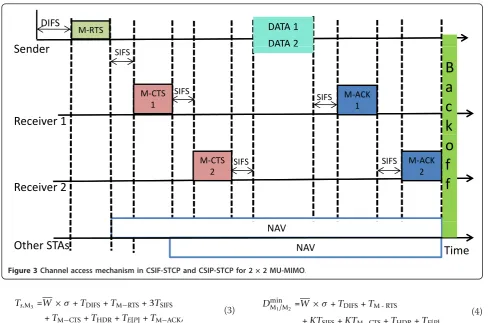
inter-ference limited precoding. Hence, in MU-MIMO aware CSMA/CA, when the transmitting node has packets to send it first acquires the channel using the CSMA/CA standard rule. After acquiring the channel, it transmits an extended RTS (M-RTS) packet, as shown in Figure 1,
explicitly including the information about Kreceivers
addresses,b
serially. All other fields contain the regular information as they do in legacy RTS packet [7]. After a SIFS time interval, along with other regular information, receiving nodes which are ready to receive reply with individual extended CTS (M-CTS) packet containing information that could be processed to achieve CSI. The
M-CTS and extended acknowledgement (M-ACK) packet exchange mechanisms and the frame formats are different for different modification approaches. For our investigated approaches, it is discussed in detail below.
3.1. CSI feedback from serially transmitted CTS packets (CSIF-STCP)
In this modification approach, RTS/CTS handshake can be modified to allow their receiver to feedback CSI cor-responding to received signal using M-CTS packet, as shown in Figure 2. All the receivers estimate their chan-nel from received M-RTS packet and, along with other regular information, feedback that value to transmitter by sending individual M-CTS packet after each SIFS time interval, as shown in Figure 3 for (2 × 2 MU-MIMO), according to their serial order assigned in RTS packet. Based on the information received from M-CTS packets, the transmitting node selects the best antenna element corresponding to each receiver node and then applies appropriate precoding. Similarly after each SIFS time interval, receiver nodes successfully receiving the data stream acknowledge the reception via M-ACK, serially. Therefore, this method can be consid-ered as the perfect CSI feedback method. This is the simplest and the most effective method despite the introduced overhead resulting from transmission of multiple extended M-CTS and M-ACK packets serially. This mechanism, however, reduces the cost and com-plexity in signal processing and also minimizes the risk of control packets corruption.
3.2. CSI prediction from serially transmitted CTS packets (CSIP-STCP)
is a less chance of packets being corrupted and in most of the cases prediction was found to work quite well.
3.3. CSI prediction from simultaneously transmitted CTS packets (CSIP-SmTCP)
In this modification approach, different from CSIF-STCP and CSIP-STCP, M-CTS packets are not transmitted seri-ally. Instead, they are transmitted simultaneously after a SIFS time interval by all the receiver nodes including the predefined pilot symbol in the PHY header as in CSIP-STCP. This method can be considered as a full blind chan-nel state estimation method despite the inclusion of the predefined pilot symbol. As the receiver nodes transmit in same time and frequency domain, decoding the informa-tion completely comes as blind. Nevertheless, employing available antenna elements and the appropriate signal pro-cessing, the transmitter node can predict the CSI of all the receiver nodes and can apply appropriate precoding. The M-ACK packets are also transmitted in the same way. The M-CTS frame format and the access mechanism for this approach have been shown in Figures 4 and 5, respec-tively. This mechanism reduces the overhead that could result from transmission of feedback bits as in CSIF-STCP and overhead that could result from serially transmitted M-CTS packets as in CSIF-STCP and CSIP-STCP. How-ever, this mechanism adds higher cost and complexity in signal processing and may also raise the risk of control packets corruption.
4. Numerical analysis
4.1. Mathematical analysis for achievable performance
Achievable maximum performance of a system is the performance that the system can deliver in the best case scenario. In order to emulate the best case in a wireless
network, we abide by the following assumptions:
•there is only one active transmitting node which
always has packets to send, and
•the channel is error free.
Considering the aforementioned assumptions, we ana-lyze the achievable maximum performance of our inves-tigated approaches in terms of throughput and delay.
Hereafter, we representCSIF-STCP, CSIP-STCP, and
CSIP-SmTCPas M1, M2, and M3, respectively.
4.1.1. Achievable maximum throughput
Throughput can be defined as the rate of successful transmission of the data packets in the channel. Thus,
maximum achievable throughput, Smax, for the
MU-MIMO can be expressed as
Smax=
K
j=1E[P] Ts
, (1)
where E[P] is the payload size in bits and Ts is the
time for a successfully transmitting those bits.Ts for all
the three modifications approaches, Ts,M1, Ts,M2, and
Ts,M3, are different from each other because of the
differ-ences in M-RTS, M-CTS, and M-ACK packet formats and/or exchange mechanisms. However, it is important
to note that mathematical expressions for M1 and M2
remain same as the changes only occur in frame formats but not in the exchange mechanisms.
Ts,M1/M2 =W×σ+TDIFS+TM−RTS
+ 2KTSIFS+KTM−CTS+THDR +TE[P]+KTM−ACK,
(2)
Frame Control
Duration
K*Receiver
Address
Transmitter
Address
Frame
Check
2 bytes
2 bytes
K x 6 bytes
6 bytes
4 bytes
M-RTS Frame
Figure 1M-RTS control packet format.
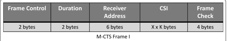
Frame Control
Duration
Receiver
Address
CSI
Frame
Check
2 bytes
2 bytes
6 bytes
X x K bytes
4 bytes
M-CTS Frame I
Ts,M3 =W×σ+TDIFS+TM−RTS+ 3TSIFS
+TM−CTS+THDR+TE[P]+TM−ACK,
(3)
where W is the average backoff value, sis the slot
time, andT(·)indicates the total time required for
send-ing respective packet. The header,HDR, consists of both
the physical and the MAC headers. By replacing Ts in
(1) withTs,M1,Ts,M2, andTs,M3, the maximum achievable
throughput for all the three modification approaches,
Smax M2 ,S
max
M2 , andS
max
M3 , can be obtained.
4.1.2. Achievable minimum delay
Access delay can be defined as the time interval from the moment a node is ready to access the medium to the moment the transmission is successfully finished. Thus, the achievable minimum delay for the investigated approaches,DminM1, DminM2, andDminM3, can be expressed as
(4) and (5). Note that mathematical expressions for M1
and M2remain same here as well.
DminM1/M2=W×σ+TDIFS+TM - RTS
+KTSIFS+KTM - CTS+THDR+TE[P],
(4)
DminM3 =W×σ+TDIFS+TM - RTS
+ 2TSIFS+TM - CTS+THDR+TE[P].
(5)
4.2. Mathematical analysis for average performance
The carried numerical analysis follows a modular approach. First, we analyze the behavior of a single tagged node by formulating a single dimensional Mar-kov model as in [25]. With the aid of the formulated
model, the probabilityτthat the node starts to transmit
in a randomly chosen slot time is calculated. Second, we express the average throughput and average packet
delay as a function ofτ. The assumptions made for the
analysis are as follows: (a) the number of nodes in the MͲRTS
DIFS
S
d
DATA 2
DATA
1
MͲCTS 1
Sender
Receiver
1
DATA
2
MͲACK 1 SIFS SIFS
SIFS
B
a
c
k
SIFS
Receiver
2
MͲACK 2 SIFS MͲCTS
2
o
f
f
NAV
NAV
Other
STAs
Time
Figure 3Channel access mechanism in CSIF-STCP and CSIP-STCP for 2 × 2 MU-MIMO.
Frame Control
Duration
Receiver
Address
Frame Check
2 bytes
2 bytes
6 bytes
4 bytes
M-CTS Frame II
network is finite (sayn), (b) the nodes always have pack-ets to transmit, and (c) the channel is ideal. For simpli-city and for maintaining easy readability of this article, we use the same notations as presented in [25] wherever applicable. The probability that a node transmits in a randomly chosen slot while employing a default conten-tion resoluconten-tion algorithm, binary exponential backoff (BEB), can be derived as in [25] and can be expressed as
τ = 1
1 + 1−1−pRp+1
R i=0
piE[b i]
,
(6)
wherepis the collision probability of the transmitted
packet, andE[bi] is the average backoff time in
conten-tion stagei, 0≤i≤R.Ris the maximum allowed
retrans-mission stage.E[bi] for stagei isW2i, where Wi is the
maximum contention window size in contention stagei.
In the stationary state, a node transmits a packet with
probability τ. Hence, the collision probability, p, i.e.
probability of transmission of other nodes at same arbi-trary time slot, can be expressed as
p= 1−(1−τ)n−1. (7)
Equations 6 and 7 represent nonlinear systems with
two unknowns, τ and p, which can be solved using
numerical methods to get a unique solution. When τ
andpare obtained, performance metrics like throughput
and delay can be derived considering other system parameters.
4.2.1. Average throughput
Throughput is one of the most important indicators to evaluate network performance. Throughput can be defined as the rate of successful transmission of the data packets over the channel. Thus, throughput for
MU-MIMO,S, can be related as
S=
PsPtr
K j=1
E[P]
(1−Ptr)Ti+PsPtrTs+ (1−Ps)PtrTs
, (8)
where Ptr is the probability that there is at least one
transmitting node active in the considered slot time, and
Psis the probability that the transmission is successful.
Ptr and Ps can be obtained easily when τ and p are
known. Ts and Tcare the average time the channel is
sensed to be busy because of successful transmission or
collision, respectively, while Ti is the duration of an
empty slot time. Ts and Tc for our investigated
approaches can be derived as follows:
Ts,M1/M2 =TDIFS+TM - RTS+ 2KTSIFS
+KTM - CTS+THDR+TE[P] +KTM - ACK,
(9)
Ts,M3 =TDIFS+TM - RTS+ 3TSIFS
+TM - CTS+THDR+TE[P]+TM - ACK,
(10)
Tc,M1/M2/M3 =TDIFS+TM - RTS. (11)
DATA 1
M-RTS
M-CTSs
DIFS
NAV
SIFS
Sender
K Receivers
Other STAs
Time
DATA 2
DATA K
M-ACKs
SIFS
SIFS
NAV
B
a
c
k
o
f
f
4.2.2. Average delay
Packet delay is defined to be the time interval from the time a packet is at the head of its MAC queue ready to be transmitted until the ACK for that packet is received.
Average packet delay,D, can be derived by following the
model in [25], and for the MU-MIMO it can be expressed as
where Sis the throughput with single antenna
ele-ment whileE[slot] = (1−Ptr)Ti+PsPtrTs+ (1−Ps)PtrTs.
Here, Ts is the average of the successful transmission
times with respective antenna elements andB0= W10.
5. Performance evaluation
We evaluate the performance numerically based on the above presented mathematical expressions taking into consideration all the parameters presented in Table 1. The selected parameters have been adopted in such a way that they could insure the interoperability between MIMO adapted and MIMO less WLANs. The MAC header and PHY header parameters are adopted from IEEE 802.11n mixed mode transmission [15]. Slight modification in headers has been applied to accomplish maximum 4 numbers of MU-MIMO receivers [23]. Rests of the parameters are adopted from IEEE 802.11g. Extended RTS and CTS frames are used as described earlier.
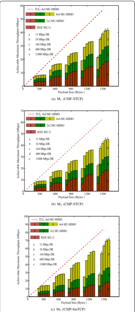
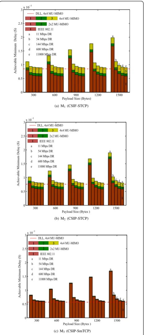
Achievable maximum throughput and achievable
minimum delay with respect toE[P] for differentX ×K
configuration and for different channel data rate (DR) are presented in Figures 6a, b, and 6c and 7a, b, and 7c,
respectively, for M1, M2, and M3. It is important to note
that the achievable throughput increases with the num-ber of antenna elements and DR, and the achievable minimum delay decreases with an increase in DR but increases with antenna elements. However, it is evident that from a PHY point of view achievable throughput
should increase with an increase in antenna elements and DR, as the channel capacity increases with them. Similarly, the achievable minimum delay should decrease with an increase in DR and should show no
Table 1 System parameters
Parameters Value
MAC header 272 bits
PHY header 40μs
ACK packet 112 bits
DIFS 50μs
SIFS 10μs
Slot time 20μs
Basic data rate 6 Mbps
Available antenna 1, 2, 4
Minimum contention window (W) 16
Maximum retry limit (R) 6
0 300 600 900 1200 1500
0
Payload Size (Bytes )
Achievable Maximum Throughput (Mbps)
---TUL, 4x4 MU-MIMO 4x4 MU-MIMO
0 300 600 900 1200 1500
0
Payload Size (Bytes )
Achievable Maximum Throughput (Mbps)
---TUL, 4x4 MU-MIMO 4x4 MU-MIMO
0 300 600 900 1200 1500
0
Payload Size (Bytes )
Achievable Maximum Throughput (Mbps)
---TUL, 4x4 MU-MIMO 4x4 MU-MIMO
Figure 6 Achievable maximum throughput of CSMA/CA
indication of changes on antenna elements variation, as simultaneous transmission with MIMO means concur-rent transmissions on same time and frequency domain. In these results, SmaxM1 <SmaxM2 <SmaxM3 and
M3. These results show the effects of
overheads associated with each of the modification approaches. As mentioned earlier, in order to solve the important MAC layer issues like MIMO functionalities information exchange and error free control packets reception, a MAC protocol needs to exchange different extended control packets with cost of additional over-head. Similarly, when the number of antenna elements increases more control packets exchange is required to associate each of the elements again in cost of addi-tional overhead. The results reveal that in the
investi-gated approaches M1 has higher overhead compared to
M2 and M3. Similarly, M2 has higher overhead
com-pared to M3. However, the resulting effects observed
here are not only from the overhead associated with extended control packets but also from basic CSMA/ CA operation and its requirement of control packets exchange in lower transmission rate. Apart from this, the results also show that the throughput does not
increase linearly in M1and M2 while in M3 it increases
more or less linearly with antenna elements but not with DR. Note that in all these cases there is no linear throughput-delay gain with respect to DR. Even for the infinite DR, the throughput bounds to throughput upper limit and delay bounds to delay lower limit. It
can also be observed that for M3, in spite of our
assumption of no additional overhead during the mod-ification, the performance goes toward bounding because of overhead related to basic CSMA/CA opera-tion and its requirement of control packets transmis-sion in lower transmistransmis-sion rate.
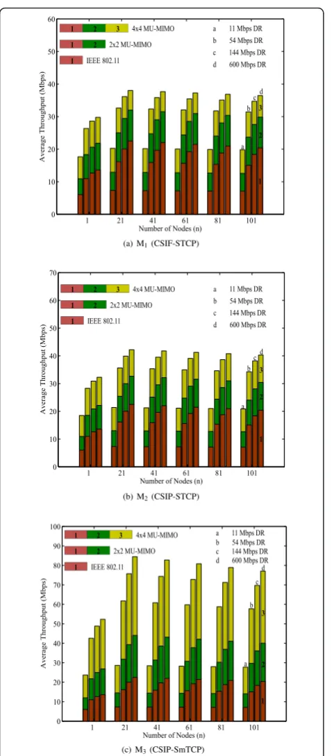
Average throughput with respect tonfor differentX×
Kconfiguration and with different DR for M1, M2, and
M3are presented in Figure 8a, b, and 8c, respectively. It
can be seen that throughput increases with antenna
ele-ments and DR. The results also showSM1 <SM2 <SM3.
These results again depict the overhead’s effect and
effects related to basic CSMA/CA operation and its requirements as mentioned above. In addition, it can be observed that throughput increases in the beginning
when n starts to increase but after reaching a certain
threshold the throughput starts to decrease. This is because when there are only fewer number of nodes there will be higher probability of the slots remaining idle because of waiting time associated with backoff algorithm. But, initially when the number of nodes starts to rise, the throughput increases as the probability of
slots remaining idle gets reduced. However, when n
increases further the probability of collision also increases which ultimately reduces the throughput. Besides these observations, the throughput does not
increase linearly in M1and M2 while in M3 it increases
more or less linearly with antenna elements like in the
300 600 900 1200 1500 0
Achievable Minimum Delay (S)
---DLL, 4x4 MU-MIMO 4x4 MU-MIMO
300 600 900 1200 1500 0
Payload Size (Bytes )
Achievable Minimum Delay (S)
---DLL, 4x4 MU-MIMO 4x4 MU-MIMO
300 600 900 1200 1500 0
Payload Size (Bytes )
Achievable Minimum Delay (S)
---DLL, 4x4 MU-MIMO 4x4 MU-MIMO
Figure 7Achievable minimum delay of CSMA/CA adapted
previous results. Figure 9a, b, and 9c shows the average
delay results for M1, M2, and M3, respectively. It can be
seen that the delay increases with antenna elements but in opposite decreases with DR. However, in these results
as well,DM1<DM2 <DM3because of overhead’s effect
and basic CSMA/CA operation’s effect as mentioned above. Moreover, it can also be remarked that the delay
increases with n in all the cases as the addition in
1 21 41 61 81 101
Number of Nodes (n)
Average Throughput (Mbps)
Number of Nodes (n)
Average Throughput (Mbps)
Number of Nodes (n)
Average Throughput (Mbps)
Figure 8Average throughput of CSMA/CA adapted MU-MIMO
aware MAC protocols for WLANs.(a)M1(CSIF-STCP),(b)M2 (CSIP-STCP),(c)M3(CSIP-SmTCP)
1 21 41 61 81 101
Number of Nodes (n)
Average Delay (S)
Number of Nodes (n)
Average Delay (S)
Number of Nodes (n)
Average Delay (S)
Figure 9Average delay of CSMA/CA adapted MU-MIMO aware
number of nodes causes the higher probability of colli-sion and leads to high waiting time. Similar to the pre-vious results, there is no linear throughput-delay gain in these results as well.
As far as we have discussed, the major factor that bounds throughput and delay is the overhead asso-ciated per successful data transmission when adapting conventional CSMA/CA. Clearly, from our results, the
overhead’s effect can be reduced at the cost of
com-plexity. Hence, performance and complexity can be flexibly traded off against each other. Apart from this, in MIMO aware CSMA/CA, along with the modifica-tions in control packet formats and/or channel access mechanism, other schemes to reduce overheads like frame aggregation, block acknowledgement, etc., [5] should also be investigated parallelly to better utilize MIMO capacity.
6. Conclusion
We characterized the performance of CSMA/CA adapted MU-MIMO aware MAC in widely deployed IEEE 802.11 WLANs. Along with the discussion on modification approaches that best represent the possible ways that could be carried out to upgrade conventional CSMA/CA into MU-MIMO aware CSMA/CA, we pro-vided their detail performance analysis, based on the analytical modeling and derived expressions, in terms of throughput and delay. Thus, on the one hand, after pre-senting the importance of MU-MIMO aware MAC pro-tocol, we presented the discussion on modification approaches and the analytical model to understand their performance, while on the other hand, we also showed the limitations of such protocols because of the effects of indispensable overhead associated.
Endnotes a
To decode simultaneously transmitted signals, it demands high computational complexity with
sophisti-cated hardware filters. bSize of the RTS “Receiver
Address”field is increased byK- 1 times in M-RTS.
Acknowledgements
This study was supported by the Basic Science Research Program through the National Research Foundation of Korea (NRF) grant funded by the Korea government (MEST) (2009-0075016).
Competing interests
The authors declare that they have no competing interests.
Received: 3 March 2011 Accepted: 27 October 2011 Published: 27 October 2011
References
1. GJ Foschini, MJ Gans, On limits of wireless communications in a fading environment when using multiple antennas. Wireless Personal Commun.6, 311–335 (1998). doi:10.1023/A:1008889222784
2. SM Alamouti, A simple transmit diversity technique for wireless communications. IEEE J Sel Areas Commun.16, 1451–1458 (1998). doi:10.1109/49.730453
3. AJ Paulraj, DA Gore, RU Nabar, H Bolcskei, An overview of MIMO communications–a key to gigabit wireless. Proc IEEE.92(2), 198–218 (2004). doi:10.1109/JPROC.2003.821915
4. D Gesbert, M Shafi, DS Shiu, PJ Smith, A Naguib, From theory to practice: an overview of MIMO space-time coded wireless systems. IEEE J Sel Areas Commun.21(3), 281–302 (2003). doi:10.1109/JSAC.2003.809458
5. Y Xiao, Efficient MAC strategies for the IEEE 802.11n wireless LANs. Wireless Commun Mobile Comput.6, 453–466 (2006). doi:10.1002/wcm.274 6. CK Pan, YM Cai, YY Xu, Channel-aware multi-user uplink transmission
scheme for SIMO-OFDM systems. Sci China Ser F Inf Sci.52(9), 1678–1687 (2009). doi:10.1007/s11432-009-0077-x
7. IEEE 802.11 Part 11: Wireless LAN Medium Access Control (MAC) and Physical Layer (PHY) Specifications (2007)
8. LX Cia, H Shan, W Zhuang, X Shen, JW Mark, Z Wang, A distributed multi-user MIMO MAC protocol for wireless local area networks, inProc IEEE GLOBECOM, 1–5 (2008)
9. J Mirkovic, J Zhao, D Denteneer, A MAC protocol with multi-user MIMO support for ad-hoc WLANs, inProc PIMRC, 1–5 (2007)
10. T Zhou, Y Yang, SJ Eggerling, Z Zhong, H Sharif, A novel distributed MIMO aware MAC protocol design with a Markovian framework for performance evaluation, inProc MILCOM, 1–6 (2008)
11. F Kaltenberger, D Gesbert, R Knopp, M Kountouris, Correlation and capacity of measured multi-user MIMO channels, inProc PIMRC, 1–5 (2008) 12. D Gesbert, M Kountouris, RW Heath Jr, CB Chae, T Salzer, From single user
to multiuser communications: shifting the MIMO paradigm. IEEE Signal Process Mag.24(5), 36–46 (2007)
13. H Bolcskei, MIMO-OFDM wireless system: basics, perspectives, and challenges. Wireless Commun IEEE.13(4), 31–37 (2006)
14. K Nishimori, R Kudo, N Honma, Y Takatori, O Atsushi, K Okada, Experimental evaluation using 16 × 16 multiuser MIMO testbed in an actual indoor scenario, inProc APS, 1–4 (2008)
15. IEEE Std 802.11n™-2009 Part 11: Wireless LAN Medium Access Control (MAC) and Physical Layer (PHY) Specifications Amendment 5: Enhancement for Higher Throughput (2009)
16. YG Lee, S Choi, Ongoing evolution of WiFi, inBroadband Wireless Access and Local Networks: Mobile WiMAX and WiFi, ARTECH House, INC, 555–576 (2008)
17. IEEE, IEEE p802.11-Task Group AC [online document], 09 June 2011. http:// www.ieee802.org/11/Reports/tgac_update.htm
18. IEEE, IEEE p802.11-Task Group AC [online document], 09 June 2011. http:// mentor.ieee.org/802.11/dcn/10/11-10-1361-03-00ac-proposed-tgac-draft-amendment.docx
19. H Kwon, JM Cioffi, MISO broadcast channel with user-cooperation and limited feedback, inProc ISIT, 1694–1698 (2009)
20. J Lee, N Jindal, Dirty paper coding vs. linear precoding for MIMO broadcast channels, inProc ACSSC’06, 779–783 (2006)
21. M Sadek, A Tarighat, AH Sayed, Active antenna selection in multiuser MIMO communications. IEEE Trans Signal Process.4, 1498–1510 (2007)
22. Y Xiao, J Rosdahl, Throughput and delay limits of IEEE 802.11. IEEE Commun Lett.6(8), 355–357 (2002). doi:10.1109/LCOMM.2002.802035 23. E Kartsakli, N Zorba, L Alonso, C Verikoukis, Multiuser MAC protocols for
802.11n wireless networks, inProc IEEE ICC’09, 1–5 (2009)
24. S Zhou, Z Niu, Distributed medium access control with SDMA support for WLANs. IEICE Trans Commun.E93-B, 961–970 (2010). doi:10.1587/transcom. E93.B.961
25. G Bianchi, I Tinnirello, Remarks on IEEE 802.11 DCF performance analysis. IEEE Commun Lett.9(8), 765–767 (2005). doi:10.1109/LCOMM.2005.1496609
doi:10.1186/1687-1499-2011-141