R E S E A R C H
Open Access
Performance enhancement of overlapping
BSSs via dynamic transmit power control
Xiaoying Lei
*and Seung Hyong Rhee
Abstract
In densely deployed wireless local area networks (WLANs), overlapping basic service sets (BSSs) may suffer from severe performance degradations. Mobile stations in a BSS may compete for channel access with stations that belong to another BSS in such environment, and it reduces overall throughput due to the increased collision probability. In this paper, we propose a new scheme for transmit power control, which enables mobile stations to dynamically adjust their transmit powers. Using our mechanism, those stations in different BSSs will have more chances of simultaneous transmissions and thus improve their performances by enhancing spatial reuse. We develop a Markov chain model to analyze the performance of the proposed scheme and also perform extensive simulations. Both the analytical and simulation results show that our mechanism effectively improves the network performance of WLANs.
Keywords: IEEE 802.11 MAC; Overlapping BSSs; Interference; Transmit power
1 Introduction
As IEEE 802.11 wireless local area networks (WLANs) have been widely deployed in homes, offices, and pub-lic places [1], the high density of WLANs has posed a great concern on the problem of co-channel interferences. Thus, the overall network performance of WLANs may be severely degraded unless an efficient scheme is provided to reduce the interference.
A WLAN basic service set (BSS) is typically formed by an access point (AP) and a number of stations associated with the AP [2], and in that case, data transmissions are allowed only between the stations and the AP. When the coverage of nearby co-channel BSSs overlaps with each other, they are called overlapping BSSs (OBSSs) [3]. In case a station located at the overlapping area transmits frames, other stations of the neighbor BSS may sense the transmission and refrain their transmissions. Also if they cannot sense the transmission, then they will become hid-den terminals to the transmitter. Therefore, the chance of simultaneous transmissions among OBSSs is reduced, and thus the whole network may suffer from the poor spatial reuse of OBSSs.
*Correspondence: [email protected]
Department of Electronics Convergence Engineering, Kwangwoon University, 447-1, Wolgye Dong, Nowon-GU, Seoul, Korea
Many solutions have been suggested so far to dynam-ically control the transmit power of WLAN stations and thus to improve the overall throughput of the network [1,4-8]. By adopting those schemes, stations are able to reduce their transmission ranges using only proper amount of transmit power, such that more stations can simultaneously transmit and thus the overall throughput is increased. The previous works, however, may not be adopted in a practical WLAN system: For example, the problem of how to determine the proper power level is not fully investigated in [1,4]. Also [6] is based on assump-tions that may not be possible in real world, [7] requires the real-time adaptation of a measurement algorithm, and power control scheme in [8] is limited to use only inad hocmode.
In this paper, we propose a method for dynamic trans-mit power control to enhance the throughput of OBSSs. First, we study the four different radio ranges in 802.11 systems and how OBSSs interfere with each other in a density WLAN. Based on these observations, we propose a new power control scheme such that every station keeps a table for recording the path loss between itself and the neighbor BSS stations from which request to send/clear to send (RTS/CTS) frames can be overheard. Utilizing the information, those stations adjust their transmit powers and data frames are delivered using only the proper pow-ers. We develop a discrete-time Markov chain model in
Section 4. The extensive simulation results are reported in Section 5, and finally, concluding remarks are drawn in Section 6.
2 Problem definition and related works 2.1 Problem definition
There are four different radio ranges in 802.11 systems as illustrated in Figure 1 [9]: transmission range, net allo-cation vector (NAV) set range, clear channel assessment (CCA) busy range, and interference range. Transmission range is the range from a transmitter (T) and represents the area within which the receiver station (R) can receive a frame successfully. The NAV set range is the area within which the wireless stations (A, B) can set the NAVs cor-rectly, based on the duration/ID information carried in the RTS/CTS frames. CCA busy range is the area within which the wireless stations (C, D) can physically sense the
Figure 1A sketch of the radio ranges during a four-way frame exchange [9].
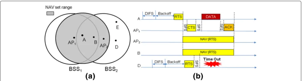
locates at the overlapping area, begins a transmission, neighbor AP (i.e., AP2) and other stations (such as B) will sense the transmission and set their NAVs. Also other neighbor stations which are hidden terminals to the sender A, e.g., D and E, may try to access channel. In case D successfully transmits a data frame to AP2, the AP cannot response with an ACK in time since it has set NAV. Due to the unsuccessful transmission, D increases its contention window and contends for retrans-mission. In this example, we can see that transmission from one BSS can hamper the operation of neighbor BSSs. This problem of the 802.11 WLANs comes from the fact that each station must rely on its direct experience in estimating congestion, which often leads to asymmetric views [10].
2.2 Related works
Several attempts have been made to improve the perfor-mance of 802.11 MAC by utilizing transmit power control scheme. Since the transmit power control (TPC) method standardized in the IEEE 802.11 suffers from inaccuracies, Oteri et al. [4] propose a fractional CSMA/CA scheme by combining the TPC with user grouping and inter-BSS coordination to improve the performance of overlapping BSSs. However, their approach lacks of a mechanism for determining the proper transmit power. In [6], an itera-tive power control algorithm is proposed to increase the number of concurrent transmissions in the dense wireless networks. This proposal is based on the assumptions that every node has complete knowledge of the network topol-ogy and current configuration, which may not be possible in real world.
Figure 2A simple scenario of OBSSs.(a)Topology of OBSSs and(b)transmission process for OBSSs.
tune their transmit powers such that they can transmit simultaneously without interfering with each other.
For performance enhancement of OBSSs, many recent works have provided different approaches. Li et al. [11] propose an interference avoidance algorithm to mitigate the interference from the neighbor BSS operating at the same channel. However, this scheme enables AP to drop its defer threshold to energy detect threshold when trans-mitting to stations located at overlapping area. Thus a hidden terminal to AP can sense the transmission from AP and the collision probability is reduced. Fang et al. [12] propose a PCF-based two-level carrier sensing mech-anism which adopts two NAVs in stations, namely self BSS network NAV (SBNAV) and OBSSs network NAV (OBNAV). When a transmission processes in one of the BSSs, the station which senses it sets the value of its NAV to be either SBNAV or OBNAV, whichever is bigger. If there are no OBSSs, the OBNAV is set to 0. In [13], an interfer-ence packet detection scheme in link layer is proposed, in which a receiving station that detects interference packets reports the existence of another BSS to AP. Then the AP announces channel switching to all stations in its BSS for avoidance of interference. There is no guarantee that the chosen channel is free from interference though.
3 Dynamic transmit power control
Our proposed dynamic TPC (DTPC) scheme is presented in this section. In the DTPC, the stations located at overlapping area are referred as interference prone (IP) stations adopting the notion in [11]. As all the stations continually monitor the ongoing transmissions, combin-ing with the information recorded in the path loss table, a station can determine whether it can start a concur-rent transmission. Then all the stations which try to start concurrent transmissions adjust their transmit powers to proper levels and compete for channel access. If one sta-tion is successful to access the channel, then since its transmission uses a low power, more stations may become hidden terminals to the transmitter. Thus we propose all the stations to use RTS/CTS procedure where the
RTS/CTS frames are exchanged using their maximum powers.
Our DTPC scheme enables the performance enhance-ment in two aspects: First, when a transmission from an IP station is ongoing, another station which belongs to a neighbor BSS and is not a hidden terminal to the IP sta-tion can start a simultaneous transmission after tuning the transmit power. Second, if a hidden terminal starts a transmission in parallel with the IP station, the neighbor AP can adjust its transmit power for timely ACK response, which means a successful transmission.
3.1 NAV reset timer modification
A timer named RESET_NAV is defined in the IEEE 802.11 MAC for NAV update [14]. The stations overhearing an RTS set their NAVs and also set the timer RESET_NAV with a duration ofCTS_Time+2SIFS_Time+2Slot_Time. Here, CTS_Time is calculated from the length of the CTS frame and the rate at which the CTS frame is transmitted. After setting the timer, the stations will reset their NAVs if they overhear DATA frame from the RTS sender.
mum power. Also it is assumed that all BSSs adopt a same value of maximum transmit power. Two more fields are added into the RTS frame, reception power and signal to interference and noise (SINR). When a station trans-mits an RTS frame on maximum power, it piggybacks the reception power of the beacon it received recently and SINR of the beacon. Note that
SINRj=
Ptra×Gij
Nj
,
where Ptra is the transmit power of senderi, Gij is the
path loss between sender i and receiver j, and Nj is
the noise and interference experienced in j. Thus when the AP receives the RTS, it can calculate the path loss from the sender. Also a neighbor BSS station which over-hears the RTS packets can calculate the path loss between the sender and itself, by adopting the allowable maximum transmit power. As the RTS/CTS frames are exchanged on the maximum power, it prevents hidden terminals and exposed terminals in a wide range. After the RTS/CTS frame exchanged, the sender adjusts its transmit power to a low level and delivers a data frame SIFS later.
In DTPC, each station keeps a table for recording recep-tion power of beacon frame and path loss between itself and the neighbor BSS stations from which it can over-hear an RTS/CTS frame, i.e. <nodeid,pathlossij,prev>. AP
keeps a table for its own BSS stations and neighbor BSS stations located at overlapping area. When a station over-hears an RTS/CTS frame, it updates the record related to
BSS received a beacon from its AP, andPj_trbe the
trans-mit power of station j in secondary BSS. Also let Ii be
the noise and interference that stationiexperienced,Gij
be the path loss between station i and station j assum-ing a symmetric channel, and letSINRi be theSINRthat
i experienced when it received a frame from its AP. In order to guarantee that transmissions fromjdoes not dis-turb ongoing transmission ini, the following condition is required.
Pi_re
Ii+PGj_ijtr
> γ. (1)
AsIi= SINRPi_rei, after rearrangement of (1), we can get
Pj_tr<
Pi_re·Gij(SINRi−γ )
SINRi·γ
. (2)
In order to guarantee the transmission from station j can be received by its AP successfully, the condition below should be satisfied:
Pj_tr×GAP_j
IAP > γ
. (3)
Rearranging (3) gives
Pj_tr>
IAP×γ
GAP_j
, (4)
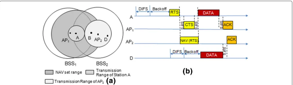
Figure 4Proposed scheme works in a hidden terminal environment.(a)Radio range and(b)transmission process.
where GAP_jis the path loss between stationjand its AP.
Combining (2) and (4), the transmit power of stationjcan be adjusted as follows:
IAP×γ
GAP_j <
Pj_tr<
Pi_re·Gij(SINRi−γ )
SINRi·γ
. (5)
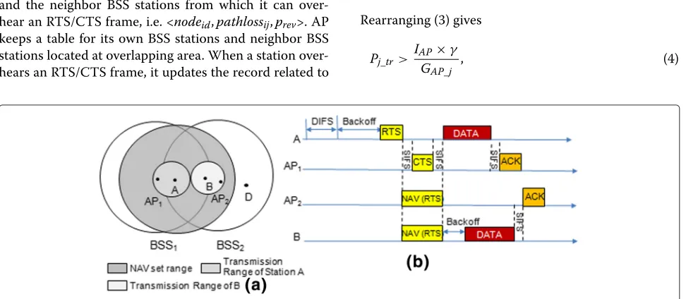
3.4 Transmissions in a non-hidden terminal environment We consider the proposed DTPC in a non-hidden ter-minal environment. The network topology is given in Figure 2a, and we use Figure 3a to illustrate the radio ranges of stations while using Figure 3b to present the transmission process. As shown in Figure 3b, the RTS frame of station A contains the reception power of the recently received beacon from AP1and SINR of the bea-con. The stations which belong to BSS2and overhear this transmission (e.g., station B and AP2) will set their NAVs and RESET_NAV timers. After A receives a CTS from AP1, it tunes its transmit power and transmits a data frame. The stations which set NAVs according to the RTS frame but cannot sense the following data frame will expe-rience the RESET_NAV timer’s time-out and enter into the BO process. Station B, whose BO counter reaches 0 first, accesses the channel and delivers a data frame after adjusting its transmit power.
Figure 5State transition diagram.
3.5 Transmissions in a hidden terminal environment Now we use Figure 4a and Figure 4b to consider the trans-mission process of DTPC in a hidden terminal scenario. The network topology is the same as depicted in Figure 2a. When station A transmits an RTS frame, AP2overhears it and sets its NAV as shown in Figure 4b. Then after receiv-ing a CTS frame from AP1, station A adjusts its power level and transmits its data frame on a possible low power. As AP2cannot overhear this data frame, its RESET_NAV timer expires and it will not set NAV when station A is exchanging data frame with AP1. D which is a hidden terminal to station A, after sensing the channel is idle, transmits a data frame to AP2during A’s ongoing trans-mission. AP2adjusts its power level based on (5) and then responses with an ACK SIFS later.
4 Performance analysis
In order to analyze the performance of the proposed scheme compared to 802.11 MAC, we develop an analyt-ical model using the discrete-time Markov chain in this section.
4.1 Markov chain model
While an ongoing transmission in a BSS prevents trans-missions in a neighbor OBSS in the legacy 802.11 MAC, in our proposed scheme, however, the OBSSs are allowed to transmit simultaneously. Thus, in order to compare the channel utilization of the proposed scheme (DTPC) and the legacy MAC, we make an assumption that the co-channel is divided into two sub co-channels, and each BSS
Table 1 System parameters
Parameters Value
N Number of sub channels 2
p Transmission probability 0.05
q Termination probability 0.1
Figure 6Analysis results.(a)Throughput vs. number of stations;(b)throughput vs. transmission probability. may occupy one of them. Adopting slotted time, in order
to make the model Markovian, we suppose that the packet lengths which are integer multiples of slot durations are independent and geometrically distributed with parame-terq (i.e., packet duration has a mean of1/q slots) [15]. Also we assume that devices always have packets to send to AP in each time slot, and each device attempts to trans-mit with probabilityp. In addition, it is assumed that there are no hidden or exposed terminals in domestic BSS.
LetXn be the number of transmissions ongoing in the
two sub channels at timen. Since each BSS can process one transmission during a time slot, the state space for the model is given byS = {0, 1, 2}. Note that the value ofXn
can be 2 only when two BSSs process a transmission at the same slot. The relationship betweenXn+1andXncan be
written as follows:
Xn+1=Xn+Sn−Tn,n≥0,
whereSnis the number of new transmissions successfully
started at timen, andTnis the number of terminations at
timen. Note thatSn=1 if a new transmission starts
suc-cessfully in time slotnandSn = 0, otherwise. IfXn = 2,
which means that both BSSs are processing transmissions, thenSn = 0 with probability 1. The number of
termina-tionsTnat timenranges from 0 toXn. IfXn = 0, then
Tn=0 with probability 1.
When a station has a frame to transmit, it attempts to transmit with probabilityp. Ifkstations are transmitting in the current slot, then the success probabilityDkin the
next time slot is
Dk =Kp(1−p)L−1,
where L is the number of stations. Also the probability R(j)k thatjtransmissions are finished when the system is in statekis given by
R(j)k = Pr[j transfers terminate at time t|Xt−1=k]
=
k j
qj(1−q)k−j.
Table 2 Simulation parameters
Parameters Value
Transmission rate 54 Mbps
Path loss exponent 2
SINR threshold 2.5 dB
Maximum transmit power 0.1 W
Normal transmit power 0.005 W
Now the transmission probability matrix for the model can be computed as follows:
P=
⎡
⎣11−−DD0(0D11−R(1D1)0)−−DD1R01(D0)0 D1R1(0)(1D−0(1D0)−+D0)D0D1R(10) D0DD01DR0(10)
R(22) R(21) R(20)
⎤ ⎦.
The state transition diagram of the Markov chain model for OBSS operations is depicted in Figure 5. In the devel-oped Markov model, the legacy 802.11 MAC and our pro-posed DTPC differ only in transition probability. Detailed transition probabilities of both cases are omitted here due to the space limitation.
4.2 Capacity analysis
The average utilizationρper sub channel can be obtained as
ρ=
i∈siπi
N ,
whereπi is the limiting probability that the system is in
stateiandSis the state space of the Markov chain. Then the overall system throughput is given by
TH = N×C×ρ,
whereCis the channel bit rate. We study the performance of our proposed scheme compared to that of the legacy MAC using the parameters shown in Table 1.
Figure 6a shows the variation of whole network throughput according to the number of stations in each BSS. Throughputs of both proposed DTPC and the legacy 802.11 MAC decrease as the number of stations increases. The figure proves the effectiveness of our proposed scheme in enhancing the throughput. One can see that the throughput can be increased by around 40 Mbps. Figure 6b shows the dependency of the throughput on the transmission probability. The throughputs of both schemes reach their peaks when the transmission proba-bility is around 0.06. The figure proves once again that our proposed scheme improves the network throughput.
4.3 Additional issues
In the Markov chain model, we have assumed that there are no hidden or exposed stations in the domestic BSS and a transmission is completed successfully. In a practi-cal network, however, the hidden and/or exposed stations may exist and they will introduce collisions. In order to make the analysis more accurate, our future works will include the study on how to model the probability that a transmission completed successfully in a time slot.
Also, we have analyzed two overlapping BSSs. Modeling the performance of multiple OBSSs, however, becomes more challenging, as the transition probabilities in both legacy scheme and proposed solution are dependent on the network topologies. Especially, based on the location of a transmitting station, the possibility whether a neigh-bor BSS can process a concurrent transmission in a time slot becomes more complex. We plan to investigate this issue in our future work.
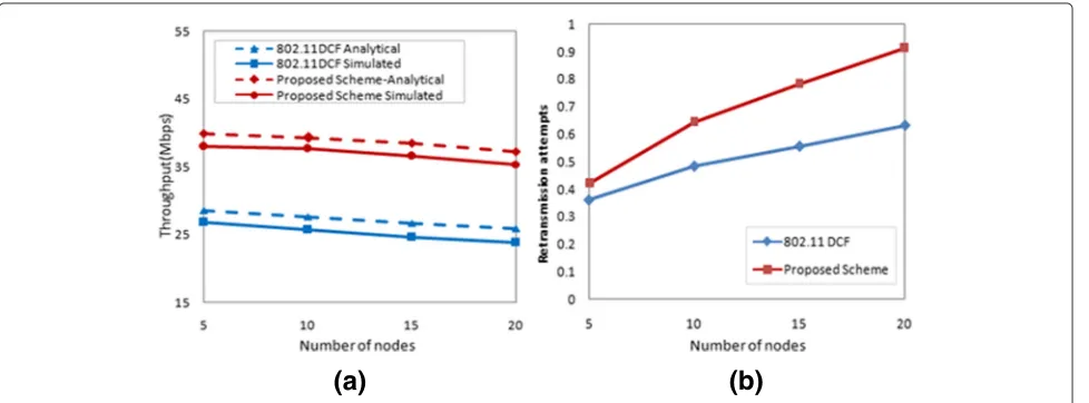
5 Simulations
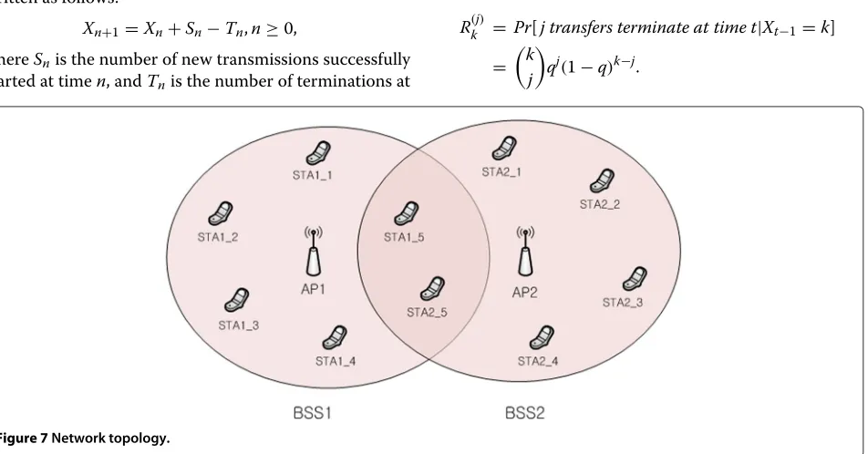
We conduct extensive simulations of proposed DTPC using OPNET. The network size is set to 300×300m2and two overlapping BSSs are processing their transmissions
size, where the number of member stations in each BSS varies from 5 to 20. We can see that the simulation result closely follows the analytic data and our proposed scheme enhances the overall network performance. Note that as the stations in legacy 802.11 MAC contend for access-ing channel with the stations in another BSS, one BSS is allowed to transmit. The proposed DTPC, however, enables the stations to dynamically adjust their transmit powers such that other stations in different BSSs can have more opportunities of simultaneous transmissions.
Figure 8b presents the retransmission attempts versus the network size. We find the retransmission attempts in our proposed scheme are lower than that of the legacy one. It can be achieved by the fact that our proposed scheme enables RTS/CTS frames to be transmitted on a maximum power and it prevents hidden and exposed ter-minals occurring in a wide range. In addition, unlike the legacy scheme, the neighbor AP can adjust its power to a proper level such that it can respond with immediate ACKs.
6 Conclusions
In this paper, we have presented a dynamic transmit power control scheme, namely DTPC, for enhancing the performance of OBSSs. Stations can dynamically adjust their transmit powers using the proposed DTPC, which enables the overlapping BSSs to transmit simultaneously and to enhance the spatial reuse. We have developed a Markov chain model in order to analyze the perfor-mance of DTPC, and the simulation results prove that the analytical model is properly built. Both analytic and simu-lation results show that the proposed DTPC significantly improves the performance of OBSSs. As the future work, we plan to investigate the performance of DTPC operating in multiple OBSSs rather than two OBSSs. Also the hid-den and/or exposed terminals existed in a BSS and various network topologies should be studied as a future work.
Competing interests
The authors declare that they have no competing interests.
Acknowledgements
This work was supported by Basic Science Research Program through the National Research Foundation of Korea (NRF) funded by the Ministry of Education, Science and Technology (2013008855), and in part by the Research Grant of Kwangwoon University in 2013.
4. O Oteri, P Xia, F LaSita, R Olesen, in16th International Symposium on Wireless Personal Multimedia Communications, WPMC. Advanced power control techniques for interference mitigation in dense 802.11 networks (Atlantic, 2013), pp. 1–7
5. X Wang, H Lou, M Ghosh, G Zhang, P Xia, O Oteri, F La Sita, R Olesen, N Shah, inSystems, Applications and Technology Conference, LISAT, 2014 IEEE Long Island. Carrier grade Wi-Fi: air interface requirements and technologies (Farmingdale, 2014), pp. 1–6
6. X Liu, S Seshan, P Steenkiste, inproceedings of the annual conference of ITA. Interference-aware transmission power control for dense wireless networks, (2007), pp. 1–7
7. H Ma, J Zhu, S Roy, SY Shin, Joint transmit power and physical carrier sensing adaptation based on loss differentiation for high density IEEE 802.11 WLAN. Comput. Netw.52, 1703–1720 (2008)
8. M Cesana, D Maniezzo, P Bergamo, M Gerla, inVehicular Technology Conference 2003. Interference aware (IA) MAC: an enhancement to IEEE802.11b DCF (Orlando, Florida, USA, 2003), pp. 2799–2803 9. D Qiao, S Choi, A Jain, KG Shin, inProceedings of the 9th annual
international conference on mobile computing and networking. MiSer: an optimal low energy transmission strategy for IEEE 802.11a/h (San Diego, California, USA, 2003), pp. 161–175
10. X Wang, GB Giannakis, CSMA/CCA: a modied CSMA/CA protocol mitigating the fairness problem for IEEE 802.11 DCF. EURASIP J. Wireless Commun. Netw.2006, 039604 (2006)
11. Y Li, X Wang, SA Mujtaba, inVehicular Technology Conference, 2003. Co-channel interference avoidance algorithm in 802.11 wireless LANs (Orlando, Florida, USA, 2003), pp. 2610–2614
12. Y Fang, D Gu, AB McDonald, J Zhang, inThe 14th IEEE Workshop on Local and Metropolitan Area Networks. Two-level carrier sensing in overlapping basic service sets (BSSs) (Island of Crete, Greece, 2005), p. 6
13. T Tandai, K Toshimitsu, T Sakamoto, inPersonal, Indoor and Mobile Radio Communications, 2006. Interferential packet detection scheme for a solution to overlapping BSS issues in IEEE 802.11 WLANs (Finland, 2006), pp. 1–5
14. IEEE 802.11-2012. Part 11, Wireless LAN medium access control (MAC) and physical layer (PHY) specifications. IEEE (2012)
15. J Mo, H-S So, J Walrand, Comparison of multichannel MAC protocols. IEEE Trans. Mobile Comput.7(1), 60–65 (2008)
Submit your manuscript to a
journal and benefi t from:
7 Convenient online submission 7 Rigorous peer review
7 Immediate publication on acceptance 7 Open access: articles freely available online 7 High visibility within the fi eld
7 Retaining the copyright to your article
![Figure 1 A sketch of the radio ranges during a four-way frameexchange [9].](https://thumb-us.123doks.com/thumbv2/123dok_us/954077.1116683/2.595.57.290.433.703/figure-sketch-radio-ranges-way-frameexchange.webp)