R E S E A R C H
Open Access
Alternative relaying for cooperative
multiple-access channels in wireless vehicular
networks
Peng Xu
1*, Zhiguo Ding
2, Xuchu Dai
1, Ioannis Krikidis
3and Athanasios V Vasilakos
4Abstract
In this paper, a novel spectrally efficient half-duplex cooperative transmission protocol is proposed for cooperative multiple-access channels in wireless vehicular networks, where multiple sources (vehicles) deliver messages to a common destination (roadside base station or roadside infrastructure) with the help of multiple decode-and-forward relays (roadside stations). The basic idea is to apply superposition coding at each transmitter in order to achieve the full diversity gain, where the linear zero-forcing detection is used at each relay to combat inter-relay interference. Compared to existing uplink cooperative protocols, the proposed scheme can exploit the cooperation involving both the relays and the sources. An achievable diversity-multiplexing trade-off is developed for the proposed transmission protocol. Even with strong inter-relay interference which has been ignored by many existing works, the proposed scheme can still approach the optimal multiple-input single-output upper bound. Numerical results have also been provided to demonstrate the performance of the proposed protocol.
Keywords: Cooperative multiple access; Wireless vehicular network; Alternative relaying; Diversity-multiplexing trade-off
1 Introduction
1.1 Background
Recent researches have paid much attention to wire-less vehicular ad hoc networks (VANETs) since they are important to intelligent transportation, environment monitoring, etc [1,2]. Unlike the cellular networks, there does not exist a powerful base station in a vehicularad hoc network, so peer-to-peer transmission is relied on. Cor-respondingly, a key problem is how to design the routing protocols to efficiently forward the source messages to the destination. One potential method is to design cross-layer protocols for mobile vehicularad hocnetworks. For exam-ple, the work in [3] has shown that cooperative transmis-sion, a low-cost and effective alternative to multiple-input multiple-output (MIMO) techniques to enhance the phys-ical layer performance, can bring its physphys-ical layer benefits to the upper layer, such as the design of routing protocols.
*Correspondence: [email protected]
1Department of Electronic Engineering and Information Science, University of Science and Technology of China, Huangshan Road, P.O.Box No.4, 230027, Hefei, Anhui, China
Full list of author information is available at the end of the article
Motivated by these benefits of cooperative transmission, this paper aims to design a novel cooperative transmis-sion scheme for the multiple access channel (MAC) in the wireless vehicular networks.
Exploring cooperation among the source nodes has been studied in [4,5] for the MACs. The work in [4] pro-posed a cooperative multiple-access (CMA) transmission protocol using amplify-and-forward (AF) strategy, and its decode-and-forward (DF) version has been proposed in [5] by using superposition (SP) coding at each source, where the idea of superposition coding was first proposed in [6] to increase the system capacity. Specifically, the key idea of such superimposed cooperative schemes is that each user will share parts of its power with other users and transmit a mixture of its own and others’ information. The diversity-multiplexing trade-off (DMT) [7] achieved by these schemes can approach the optimal multiple-input single-output (MISO) upper bound. However, such schemes only exploit the cooperation among the sources and are therefore constrained by the number of sources.
1.2 Related work
To further improve the reception robustness, exploiting relays as an extra dimension has been recognized as a cost-effective way, since the number of idle users is always larger than the active ones in a typical wireless network. However, extra time slots may be consumed to repeat source messages in relay transmission. For example, due to the half-duplex constraint, there exists a loss of spec-tral efficiency for the classical orthogonal transmission schemes [8,9]. The standard non-orthogonal transmis-sion strategies in [4,10] can make some improvement and achieve the full multiplexing gain but still suffer a significant diversity loss for large multiplexing gains, if compared with the optimal MISO upper bound. To overcome limitation of the available diversity, a succes-sive relaying concept which aims to physically reuse the relay-destination channels was studied in [11-14]. The basic idea is to arrange two or more relays to alter-natively retransmit the source messages. To deal with the inter-relay interference, the inter-relay link was usu-ally assumed to be either sufficiently strong or weak in these DF-relaying works. A cooperative transmission pro-tocol named as shifted successive DF relaying (SSDFR) was proposed in [14], where maximum likelihood (ML) decoding is utilized at two multiple-antenna relays. In [15], another cooperative transmission protocol, called relay-reuse DF (RRDF), has been proposed to the sce-nario with a single source node, which yields furthermore improvement in comparison with [14] due to the linear zero-forcing (ZF) detection which can reduce the compu-tational complexity.
For a general uplink scenario with multiple users and relays, it is still a challenging problem to integrate the cooperation among the sources and the cooperation from the relays. In [16,17], each relay utilized superposition coding to assist each source. However, the developed upper bound of DMT in [16,17] can only be achieved with some assumptions on the conditions of inter-relay channels. The work in [18] considered a more general scenario and proposed a cooperative protocol, called relay-assisted CMA (R-CMA), which carefully sched-ules the multiple sources and relays’ transmission, but the optimal MISO bound can only be approached for a large number of relays. More works that considered such multi-user multi-relay networks can be found in [19-21], where the assistance of relays has been well exploited. Generally, these works only use the assis-tance of relays without the cooperation between sources, which cannot fully exploit the capacity of the uplink system.
1.3 Contribution
This paper aims to design a novel cooperative trans-mission protocol for a CMA channel to integrate the
cooperation from dedicated relays and the mutual coop-eration between users.
Specially, we consider a cooperative multiple-access communication scenario in which multiple source nodes communicate with the common destination with multi-ple half-dumulti-plex relays. Such a communication pattern is an important building block in wireless VANETs. For exam-ple, some proposals of intelligent vehicle highway systems (IVHS) have introduced a variety of vehicle-to-vehicle and vehicle-to-roadside-infrastructure communications. In this case, cooperation can take place between vehicles or between vehicles and roadside stations. When some vehicles wish to send messages to a common roadside base-station, they can cooperate with each other and also obtain external assistances from more powerful roadside stations with multiple antennas.
The proposed cooperative transmission protocol is termed as alternative-relaying decode-and-forward (ARDF) throughout this paper. The main novelty is that a new cooperative multiple-access transmission protocol has been designed by carefully applying these low-cost tools (zero-forcing detection, antenna selection, superposition coding, repetition-coded decode-and-forward, etc.) and fully exploiting the potentials of relay and source coop-eration. To the best of the authors’ knowledge, no exist-ing works can effectively achieve this full cooperation. The basic idea of the proposed protocol is to combine the superposition coding [6] with RRDF scheme [15]. By carefully arranging the transmission process and apply-ing superposition codapply-ing at transmitters, each source can be assisted by all the other nodes, including relays and other sources; by utilizing the linear ZF decoding in terms of RRDF transmission scheme, the reuse of the relay-destination links can be achievable in the scenario with a general inter-relay interference. Hence, the potential of such a system can be fully exploited, and the full diversity gain can be achievable. Antenna selection is also applied at each relay to select the best antenna for transmit-ting, which can preserve the full diversity gain and save transmit power.
outage probability performance of the proposed transmis-sion protocol.
Compared to the point-to-point communication in [15], we consider a multi-user case for the addressed MAC scenario in this paper. As a consequence, DMT for the MAC channel in [22] should be adopted, the information-theoretic criterion, which is developed based on the capacity region of MAC [23]. Specifically, defineXS = {Xi:i∈S}, andXi(Y)is the channel input (output) vari-able. For a instantaneous channel state information (CSI) which is known at the receiver, the capacity region of the M-user MAC can be written as following [23]:
i∈S
Ri < I(XS;Y|XSc,H=H)for all
S ⊆ {1, 2,· · ·,M} (1)
for some product distribution p1(x1)· · ·pM(xM), where Ri the data rate of source i (i = 1,· · ·,M) and H is the corresponding source-destination channel matrix. As can be observed from the above equation, the capacity region of MAC is a set of many inequalities with dif-ferent conditions, which makes the calculation of DMT much more difficult than the single-user scenario in [15]. These challenges also make the corresponding analysis more valuable.
This paper is organized as follows. Section 2 describes the proposed CMA-ARDF transmission protocol. Section 3 presents the details of the ARDF transmission process of the proposed scheme. Section 4 outlines the achievable DMT and the Monte Carlo simulation results for the proposed protocol. Section 5 offers concluding remarks. The proofs of the final DMT result are provided in the ‘Appendix’ section.
2 Protocol description
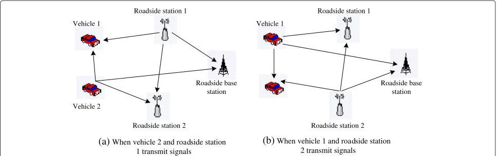
A cooperative multiple-access scenario is considered in this paper, where multiple sources wish to communicate a common destination under the help of relays. In particu-lar, the addressed scenario consists of two single-antenna sources (i.e., vehicles, denoted as S1 and S2), two Mr -antenna (Mr ≥ 2) relays (i.e., fixed roadside stations, denoted asR1andR2), and one common single-antenna destination (i.e., base station, denoted asD). The abstract system model and its application to the wireless vehicu-lar networks are shown in Figures 1 and 2, respectively. All channels are assumed to be frequency-flat quasi-static Rayleigh fading. Such a Rayleigh fading assumption is valid in a practical vehicular network since it is very likely that there does not exist a line-of-sight (LOS) compo-nent between a pair of VANET transceivers due to their relatively low antenna height [3,24,25]. All nodes are con-strained by the half-duplex assumption and use the same
transmission power. Time division multiplexing access (TDMA) is utilized in this scenario for its simplicity.
Every antenna at each relay is marked with a distinct index number from 1 toMr. As shown in Figure 1, the column vectorhi,Rj denotes the channel vector between the i-th source andRj, wherei,j = 1, 2, and hSi repre-sent the source-destination channel. The channel vector betweenRj and Dis denoted as a column vector gj = {gj,1,· · ·,gj,Mr}. Moreover, the column vectorhj,mdenotes
the inter-relay channel vector between them-th antenna ofRjand the other relay. Each relay uses all theMr anten-nas to receive messages but only chose thebestantenna to transmit signals for simplicity. The index of such a trans-mit antenna is defined asrjatRj. Note that this antenna selection method can preserve the diversity gain achieved by all the antennas at each relay in the high SNR regions.
The proposed protocol consists of two stages, initializa-tion and data transmission.
2.1 Initialization
During the initialization stage, each relay channel is assumed to have the knowledge of its incoming and outgo-ing channel state information (CSI). Based on the source-relay CSI, using the source-relay selection method in [8], we known thatRjcan decode the messages fromSiwhen the source-relay channel satisfies log(1+ρ|hi,Rj|2) >R˜. Here, log(·)is taken to base 2,ρdenotes the transmit signal-to-noise ratio (SNR), where we have assumed that all trans-mitters are under the same and fixed power constraint,| · | denotes the Euclidean norm of a vector, andR˜denotes the number of bits in each codeword transmitted by sourcesa. IfRjcan correctly decode the messages from both sources,
i.e.,|hi,Rj|2 ≥ 2 ˜
R−1
ρ for∀i∈ {1, 2}, it will broadcast a
one-bit indicator, which is denoted as ACK1. Otherwise, Rj broadcasts a one-bit indicator NACK1, assumed that all the other nodes can correctly receive each feedback sig-nal. DenoteAkas the situation in whichkrelays broadcast ACK1 signals. On the other hand, based on the relay-destination CSI, each relay can determine the index of the best antenna asrjarg maxr=1...Mr|gj,r|2.
For situationA2in which both relays broadcast ACK1 signals, two sub-events will be further considered. Accor-ding to the source-relay/inter-relay CSI,Rjwill determine whether it can use ZF detection to separate the mixture of two unknown streams which are fromSjand the other relay, respectively. For the ZF receiver, the qualification criterion [26] is
(HHRjHRj)−1
k,k < ρ/2
˜
R−1, where [X] k,k represents thek-th diagonal element of matrixX,HRj =
β1h2,r2 α1h1,R1
forj=1, andβ1h1,r1 α1h2,R2
forj=2. Note thatαiandβiare the power weighting factors at the sources and relays, respectively, which are constrained by 0 < αi,βi < 1 and
2 i=1α2i =
2
Figure 1The system model and ARDF process at two successive time slots (a-b).Each relay is equipped with multiple antennas. The antenna marked with black color for each relay is selected as the transmit antenna.
indicator ACK2. Otherwise, it sends back NACK2. LetE denote the event that both relays send back ACK2 signals, and such an event can be represented as [26]
E
⎧ ⎪ ⎨ ⎪ ⎩log
⎛ ⎜
⎝1+ ρ
(HHRjHRj)−1
k,k ⎞ ⎟
⎠>R˜,∀k,j∈ {1, 2} ⎫ ⎪ ⎬ ⎪ ⎭,
(2)
Otherwise, the system lies in eventE if any relay sends back a NACK2 signal.
2.2 Cooperative transmission
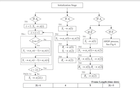
Based on the initialization stage, the transmission is divided into four different modes according to the indi-cators sent back from the two relays. The flow chart of the proposed protocol is shown in Figure 3, where each of the sources is assumed to correctly decode the messages of the other source, which is valid for high SNR regions as shown in [5]. In the next paragraphs, we will describe
the cooperative transmission mode for each situation in details.
For situationA0in which both relays send back NACK1 signals, we can only utilize the mutual cooperation between the two sources. In one cooperative data frame, each source intends to send Lcodewords, and the sys-tem works in mode 1. In time slot n(2 ≤ n ≤ 2L), Si will transmit a mixed messagebα2x(n−1)+α1x(n)and the other source listens, where i = 2 if n is even and i = 1 if n is odd. The data rate per channel use here is2L2+L1R˜.
For situation A1 in which only one relay sends back ACK1 signal, we assume thatR1is this relay without loss of generality. Each source intends to transmit only one code-word, and the system works in mode 2. For the first two time slots, the transmission process is the same as that in mode 1, andR1can correctly decodex(1)andx(2)since it sends back ACK1. In the third time slot,S1andR1will retransmitx(2)andx(1), respectively. In the fourth time slot,R1will retransmitx(2). The transmission data rate in this situation is24R˜.
Vehicle V1 ehicle 1
Vehicle 2
Roadside station 1 Roadside station 1
Roadside station 2 Roadside station 2
Roadside base station
Roadside base station
vehicle 2 and roadside station 1 transmit signals
(a)When (b) When vehicle 1 and roadside station
2 transmit signals
Figure 3The flow chart for the transmission stage.Note thatAkdenotes the situation thatkrelays broadcast ACK1 signals,k=0, 1, 2. The event
Edenotes that both relays broadcast ACK2 signals, otherwise the system lies in EventE.Lis used to denote the number of codewords transmitted by each source in the corresponding data frame.αiis power allocation factor at the sources,i=1, 2.
For situationA2, if the eventEoccurs, the system works in mode 3. The transmission scheduling during the first three time slots is the same as that in mode 2. Then, during the fourth time slot, R1 and R2 will retransmit x(2)andx(1), respectively. During the fifth time slot,R2 retransmits x(2). The data rate for the event E¯ is 25R˜. For the eventE, both relays broadcast ACK2 signals. As shown in Equation (2), each relay can correctly decode two unknown codewords transmitted by a source and the other relay, so the ARDF transmission process can be per-formed. The two sources will transmit 2L codewords to the destination during 2L+3 time slots, so the data rate is
2L
2L+3R˜. The details of such an ARDF process are put into in to the next section, i.e., Section 3, and the system works in mode 4.
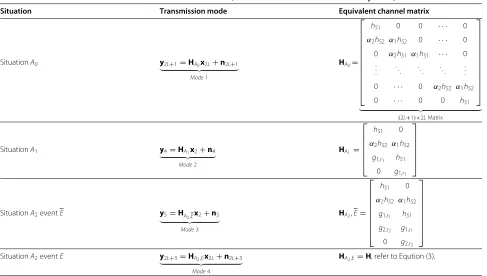
From the protocol description, the transmission mode and equivalent channel matrix for each situation can be easily shown in Table 1.
3 Alternative-relaying DF process
3.1 Transmission process
The proposed ARDF transmission process follows the concept of successive relaying [13], where the two
half-duplex relays alternatively retransmit the source messages to mimic a full-duplex node. As shown in Figure 1, the sending source sends a superposition codeword α2x
Table 1 The transmission modes for each situation, whereyi,ni∈Ci,i=4, 5, 2L+1, 2L+3;xj∈Cj,j=2, 2L
Situation Transmission mode Equivalent channel matrix
SituationA0 y2L+1=HA0x2L+n2L+1
In the following paragraphs, we will describe the trans-mission process during the four successive time slots in details.
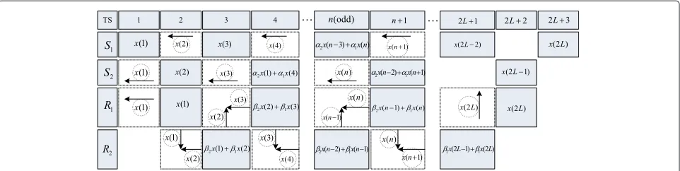
Assumento be odd without loss of generality. In time slotn(1 ≤n≤2L), the sending sourceS1first transmits x(n), whileR1 andS2 decodex(n) fromS1. In time slot n+1,R1is the sending relay and uses its best antenna to retransmitx(n);R2receivesx(n)fromR1. In time slotn+2, R2 becomes the sending relay and uses its best antenna to repeatx(n). In time slotn+3, the sending sourceS2 retransmitsx(n)again. Therefore, during such four suc-cessive time slots,x(n)can be transmitted four times, by both two sources and relays. Similar to the transmission of x(n), the codeword ofS2,x(n+1), will be transmit-ted byS2,R2,R1, andS1in time slotn+1,n+2,n+3, andn+4, respectively. When a transmitting node wishes to transmit two codewords simultaneously, it will trans-mit the superposition of these two codewords and use an amplitude factor to constrain the power of each codeword. Figure 4 illustrates the whole ARDF transmission process, where 2L+3 time slots are required for a cooperative data frame.
From the above ARDF transmission process, one can observe that the listening relay may need to decode at most two unknown codewords in a time slot. For instance, during time slot n (2 ≤ n ≤ 2L), in addi-tion to the new source codewordx(n), the listening relay also does not knowx(n−1)transmitted by the sending
relay. This is because it is transmitting during the pre-vious time slot and cannot simultaneously receive the source codeword x(n− 1) due to the half-duplex con-straint. After canceling the known codewords, this relay will decode two independent unknown codewords, i.e., x(n)andx(n−1), from one source and the other relay, respectively. Such a transmission mode mimics a two-user MAC with two single-antenna transmitters and oneMr -antenna receiver. At each relay, simple linear zero-forcing detection approaches can be used to separate the source message and the interference from the other relay, where each relay is equipped with multiple antennas and there-fore has the capability to separate the messages under the ZF condition in Equation (2).
3.2 Data model
Note that we have used a fixed power allocation strategy in each time slot, and the use of more advanced adaptive power allocation shall yield better outage performance at finite SNRs. However, for the infinite SNR region, the pre-cise power allocation does not affect the final DMT result [27].
Figure 4The ARDF process during each time slot (TS).Herenis an odd number and 5≤n≤2L−1,L≥3. The solid blocks denote that the sending relays transmit the codewords using the best antenna. Dashed blocks denote that the listening relays receive signals using all the antennas, and each codeword within the dashed circle is an unknown codeword to be decoded. The horizontal and vertical arrows imply that a node receives the corresponding codewords from sending source and the sending relay, respectively.
slots;n =[n(1),· · ·,n(2L+3)]T, which is the Gaussian additive noise vector; and the(2L+3)×(2L)equivalent channel matrix is as follows:
H=
⎡ ⎢ ⎢ ⎢ ⎢ ⎢ ⎢ ⎢ ⎢ ⎢ ⎢ ⎢ ⎢ ⎢ ⎢ ⎢ ⎢ ⎢ ⎣
hS1 0 0 0 0 · · · 0
g1,r1 hS2 0 0 0 · · · 0
β2g2,r2 β1g2,r2 hS1 0 0 · · · 0
α2hS2 β2g1,r1 β1g1,r1 α1hS2 0 · · · 0 0 α2hS1 β2g2,r2 β1g2,r2 α1hS1 · · · 0
..
. . .. . .. . .. . .. . .. ...
0 · · · 0 α2hS2 β2g1,r1 β1g1,r1 α1hS2 0 · · · 0 0 hS1 β2g2,r2 β1g2,r2 0 · · · 0 0 0 hS2 g1,r1
0 · · · 0 0 0 0 hS1
⎤ ⎥ ⎥ ⎥ ⎥ ⎥ ⎥ ⎥ ⎥ ⎥ ⎥ ⎥ ⎥ ⎥ ⎥ ⎥ ⎥ ⎥ ⎦ .
(3)
4 Diversity-multiplexing trade-off and numerical results
In this section, the analytical performance evaluation of the proposed protocol will be first shown by using DMT. Then, the Monte Carlo simulations will be carried out to demonstrate the outage performance of the proposed cooperative ARDF protocol.
4.1 Achievable diversity-multiplexing trade-off
Firstly, recall that the diversity and multiplexing gain are defined as [7]
d− lim
ρ→∞
log[Pe(ρ)]
logρ and rρlim→∞
R(ρ)
logρ, (4) wherePeis the ML detection error probability andRis the target data rate per channel use. Following similar steps in [22], it can be proved that the ML error probability in the MAC scenario can be tightly bounded by the outage probability at high SNR. So the outage probability will be focused in this paper. When lim
ρ→∞
logf(ρ)
logρ =d,f(ρ)is said
to be exponentially equal toρd, denoted asf(ρ)=. ρd(˙≤
and ˙≥are similarly defined). The following theorem gives the final DMT performance of the proposed cooperative protocol.
Theorem 1. When each relay is equipped with at least two antennas, i.e., Mr≥2, the achievable DMT of the pro-posed ARDF protocol for the two-user and two-relay CMA scenario can be expressed as
d∗(r)=(2Mr+2)
1− 2L+3 2L r
+
, (5)
where(x)+denotes max{x, 0}.
Proof 1. We have briefly provided the proof of this theorem in [28] without formal derivations. In this journal paper, the details of the proof for this theorem will be blue pre-sented in Appendix 2.
• Remark 1: The optimal MISO DMT for the addressed CMA scenario can be expressed as
dMISO(r)=(2Mr+2)(1−r), 0≤r≤1.
According to Equation (5), when the frame lengthLis sufficiently large, the achievable DMT of the proposed scheme yields 2L2+L3≈1, which demonstrates that the optimal MISO trade-offdMISO(r)can be
asymptotically approached by the proposed scheme. • Remark 2: The achievable DMT of the CMA
schemes in [4,5] can be written as
dCMA(r)=M(1−r), 0≤r≤1,
further enhance the reception robustness by exploiting the relay nodes.
• Remark 3: On the other hand, the R-CMA protocol in [18] can be straightforwardly extended to the two-user two-relay scenario considered in this paper. It means that each relay apply a simple antenna selection, and the DMT result presented in Equation (7) in [18] can be accordingly updated as
dR_CMA(r)=(1−r)+Mr(2−4r)+, 0≤r≤1.
Compared to the R-CMA scheme, the proposed scheme achieves one more diversity gain, because it exploits the help of twoMr-antenna relays while preserves the cooperation between two sources. Although the proposed protocol can only achieve a maximal multiplexing gain2L2+L3while the schemes in [18] can achieve 1, the difference is negligible for a largeL.
Figure 5 illustrates the achievable DMTs of various cooperative schemes. As can be seen from this figure, the proposed scheme can approach the optimal MISO upper bound for a sufficiently largeL, and hence, outperforms the comparable ones in most multiplexing range.
4.2 Numerical results
In this section, some numerical results based on the Monte Carlo simulations are provided for the addressed CMA scenario. The targeted data rate is set as 2 or 4 bits per channel use (BPCU). Each relay is equipped with two
0 0.1 0.2 0.3 0.4 0.5 0.6 0.7 0.8 0.9 1
0 1 2 3 4 5 6
Multiplexing gain r
Diversity gain d(r)
Optimal MISO R−CMA in [18] Proposed CMA−ARDF CMA−SP in [5]
Figure 5The DMT performance of different protocols for addressed CMA channel.Here each relay is equipped with two antennas. For the proposed protocol, the number of codewords transmitted by each source in one cooperative data frame is fixed as L=25. The two sources communicate with the destination using TDMA for all the protocols.
antennas, i.e.,Mr=2. For the proposed CMA-ARDF pro-tocol, setL=25,α1=β1=0.87 for simplicity. Note that all the channels are assumed to be Rayleigh fading with unit variance and all the nodes have the same transmit power.
In addition to the superposition-coding-based CMA in [5], the R-CMA scheme in [18] is also used to com-pare with the proposed ARDF protocol. As shown in Figure 6, ARDF has limited performance at low SNR. This is because the performance of the proposed scheme is much more sensitive to the source-relay/inter-relay chan-nel condition, and the outage event is prone to occur at each relay at low SNR, which results in some degrada-tion to the outage performance. However, the proposed scheme achieves the smallest outage probability among the comparative ones when we increase SNR. This per-formance gain is due to the fact that the proposed ARDF scheme can exploit the available relays to provide an extra dimension to improve the outage performance, whereas the scheme in [5] only considers the cooperation between the two sources and the R-CMA scheme in [18] does not consider the mutual source cooperation. Therefore, larger diversity gains can be achieved by the proposed transmission protocol, which guarantee the superior per-formance particularly at high SNR. In Figure 7, different antenna numbers, i.e., Mr, is consider at each relay to demonstrate the outage performance of the proposed scheme. One can observe that increasing the number of relay antennas can further improve the robustness of the transmission scheme, since more diversity gains can be provided.
5 10 15 20 25 30 35
10−6 10−5 10−4 10−3 10−2 10−1 100
SNR in dB
Outage Probability
SP in [5] R−CMA in [18] Proposed ARDF 2BPCU
4BPCU
Figure 6The outage probability for the proposed protocol, the superposition cooperative scheme in [5] and non-cooperative transmission.Note that each relay is equipped with two antennas. For the proposed protocol, we setL=25. The power allocation at the sources for both the proposed ARDF scheme and the SP scheme in [5] is fixed asα2
0 5 10 15 20 10−4
10−3 10−2 10−1 100
SNR in dB
Outage Probability
Mr=2,R=2 M
r=3,R=2 M
r=4,R=2 M
r=2,R=4 M
r=3,R=4 M
r=4,R=4
Figure 7The outage probability for the proposed ARDF scheme versus antenna numberMrat relays.SetL=25,α21=β12=0.87.
5 Conclusions
In this paper, a new cooperative transmission protocol has been proposed for a CMA scenario in the wireless vehicular networks. Without the use of assumptions of strong inter-relay channel in [13], the relay reuse has still been realized using the linear ZF detection at the half-duplex relays to combat a general inter-relay interference. In addition, to fully exploit the cooperation between all the transmitters, the superposition coding strategy has also been carefully applied at both sources and relays . To evaluate the spectral efficiency, an achievable DMT of the proposed scheme was developed, which demon-strated that the proposed ARDF protocol can outperform the existing related schemes and approximately achieve the optimal MISO upper bound. The derived analytical result and the numerical results have demonstrated that the proposed scheme has a better performance in compar-ison with the existing related schemes in most conditions. The impact of adaptive power allocation has not been ana-lyzed due to the high SNR considered in this paper, where a promising future direction is to carry out the study for the optimal design of power allocation to improve the overall system throughput at intermediate SNR.
Endnotes
aFor a particular situation, the data rate should be ˜
R×Nx
Nt , whereNxandNtare the number of transmitted
codewords and the number of required time slots, respectively. So thetargeteddata rateR(i.e., the average data rate) can be calculated fromR˜. We will provide more discussions about the relationship between the two rates later in this paper.
bIn this paper,x(n)denotes the new source codeword
sent bySi(i=1, 2) in time slotn(1≤n≤2L). Obviously,
the mapping criterion isx(n) = !
s1(n+21), ifnis odd s2(n2), ifnis even, wheresi(l)denotes thel-th (1≤l≤L) codeword ofSiin one cooperative frame.
Appendices
Appendix 1 Preliminary results
We first present four lemmas and their proof steps in this section. These results will be useful for the proofs of Theorem 1 in the next section.
Lemma 2. By assuming quasi-static and flat Rayleigh-fading channels, the probability of each situation Ak with k-qualified relays broadcasting ACK1 signals can be expressed as P(Ak) =. ρ−(2−k)Mr(1−˜r), where r˜ = limρ→∞logR˜(ρ)ρ.
Lemma 3. By assuming quasi-static and flat
Rayleigh-fading channels and α1 = β1 = "
1
2 for simplicity, the probability of the event E that both relays can success-fully perform ZF detection and broadcast ACK2 signals, as expressed in Equation (2), can be bounded as
1− 4γ Mr−1
(Mr−1)! ≤
P(E)≤1− 2γ Mr−1
(Mr−1)!
, (A.1)
whereγ = 2R˜−1
ρα2 1δ2
,δ2is the variance of each channel
coef-ficient. Furthermore, the probability of the event E can be obviously obtained as P(E)=. ρ−(Mr−1)(1−˜r).
Lemma 4. When X1 and X2 are subjected to exponen-tial distribution, the probability can be approximated as P(X1X2 < a) ≈ −alna,where a > 0and is sufficiently small.
Lemma 5. Assuming that z = max{z1,· · ·,zMr}, where zi is exponentially distributed with unit variance, the expectation of e−cz(c > 0)can be revealed as [e−cz]=
Mr!
Mr
i=1(c+i)
, [·]denotes the expectation of a random
vari-able.
The proofs steps of the above lemmas are provided in the following section.
Proof of Lemma 2
Denote B as the event that a relay Rj is not qual-ified, i.e., it can be expressed as the event: B #2
i=1 $
log(1+ρα12|hi,Rj|2) <R˜ %
Thus, the probability of each situationAkcan be expressed
Proof of Lemma 3
Consider a signal model in which the r2-th antenna of R2 transmits a message ˜s1 with a power lever β12 while the first source S1 broadcasts a message ˜s2 with
a power lever α12. We set α1=β1= "
1
2 for ease of explanation. Such a signal model can be found in most time slots with odd numbers in situation A2 event E. At this time, the signal vector received by R1 can be written as rR1 = HR1s˜ + w1, where rR1,w1 ∈ CMr, vector. This transmission model can be recognized as a special MIMO system with two transmit, andMrreceive antennas when ZF detection is applied. Denote the
event asER1
Applying ZF detection at the receiver and according to [26], the probability ofER1can be expressed as
P(ER1)=1− that the similar ZF decoding can be applied at R2 when R1 and S2 are transmitting messages at the same time, and ER2 is similarly defined as ER2
Then, the probability of the event E defined in Equation (2) can be revealed as P(E) = P'ER1(ER2
) , where the eventsER1andER2are not strictly independent. Since reciprocal channel is assumed, the channel vectors h1,r1 and h2,r2 have one common element which is the channel coefficient between ther1-th antenna ofR1and ther2-th antenna ofR2, so that it is difficult to obtain the
According to Equation (A.3), Lemma 3 can be proved.
Proof of Lemma 4
AssumeX1andX2to be independently exponentially dis-tributed with unit variance without loss of generality. Let D = {(x1,x2) ∈ R2+|x1x2 < a} and fx1x2(x1,x2) =
xi dx. Then, theimproper integral
acan be calculated as a=limu→0+ a(u).
Moreover, from [29] (Equation 3.351.4), Bi(u) can be calculated by the exponential integral function as
Bi(u) = (−1)i
where i ≥ 2, and exponential integral function can be shown as Ei(−u) = ln(u)+∞k=1(−k·uk)!k. Now that,Bi(u) can be obtained as
Bi(u) Equation (A.7) and rearranging the infinite series, a(u) can be rewritten as
Letv=au−1,φn(v)can be expressed as
Following similar proof steps of Corollary 1 in [15], the limit limv→+∞Fn(v) can be proved to exist. Hence, by recalling Equation (A.10), acan be expressed as
a= lim
For a sufficiently large ρ, a can be approximately calculated as a≈ −alna.
Proof of Lemma 5
It is not difficult to obtain the PDF of z as fz(z) = q. Splitting each term on the right side, Equation (A.16) can be calculated as
[e−cz]
Furthermore, by iteratively repeating the similar process in Equation (A.17), the expectation ofe−czcan be finally obtained as[e−cz]= Mr!
Mr
i=1(c+i) .
Appendix 2 Proof of theorem 1
As shown in [7,22], the ML error probability can be tightly bounded by the outage probability at high SNR, so the out-age probability will be analyzed in this section. According to [22] and the protocol description in Section 2, we can define the outage event of the proposed ARDF protocol as
O #2
k=0OAk, whereOA2 OA2,E #
OA2,E. Here,OAk
denotes the outage event in the situationAk at the des-tination,OA2,EandOA2,Eare similarly defined. Thus, the overall outage probability of the proposed protocol can be expressed as
The probabilities of each situationAk and the eventE have been presented in Lemma 2 and Lemma 3, respec-tively. Moveover, the outage probability in each situation will be analyzed in the terms of the MAC capacity region. Based on the definition in Equation (1), the source data rate constrains for the proposed-ARDF protocol can be further calculated as follows:
|S|QR˜ <log number of codewords transmitted by each source in one cooperative frame, andhl is a channel vector, both the structure of hl and the set L are a function of S and the details of their relationship toS will be discussed in the next few subsections. The outage events occur when any constraint in Equation (B.2) is not met, and the high-est outage probability achieved by each constraint is the dominant factor [22]. In the following subsections, dif-ferent values of each parameter in Equation (B.2) will be considered for different situations.
Situation A0
the outage probability at the destination in such a case can
In order to make the analysis more tractable, a(2L+ 1) × (2L + 1) square matrix 6HA0 is first defined as 6
HA0 [HA0,0], where the zero column vector is (2L+ 1)-dimensional. It is easy to show thatHA0HHA0 = 6HA06HHA0 and [I2L+1+ρ6HA06HHA0] is a tridiagonal matrix. According to [30], the determinant of the tridiagonal matrix can be shown iteratively as
Dn=[ 1+ρ(xn+yn−1)]Dn−1−ρ2xnyn−1Dn−2,
where Dn = det[I2L+1+ρH6n6HHn], andH6n denotes the n×ntop-left submatrix from6HA0,xnandyn are then -th element on -the principle diagonal and subdiagonal of 6
HA0, respectively. By using such a property and note that x2L+1=0, the following inequality can be obtained
D2L+1≥(1+ρX1) (1+ρα1X1)L−1(1+ρα1X2)L be upper bounded as
P2(OA1) ≤ P
where the last relationship is based on Lemma 4. Hence, P(OA1)˙≤ρ−(Mr+2)(1−˜r)can be obtained.
Situation A2event E
similar steps in Equation (B.7). Otherwise, S = {1, 2},
In the above equation, det .
Situation A2event E
The outage probability in situationA2eventEis difficult to be obtained using the above method, but the upper bound can be calculated by following the similar analy-sis in [17]. Firstly, model 4 in Table 1 is assumed to be a symmetric 2L-user multiple-access system where the codewordx(n) in x2L is transmitted by Sn, and such an assumption will make the analysis tractable. For the two-user case considered in this paper, the performance would not be worse than the performance of the former one. So thatL = S ⊆ {1, 2,· · ·, 2L},Q = 1,hl denotes the l-th column vector of H in Equation (3), and there are (22L−1)source data constrains in Equation (B.2). For each constraint, there exists a probability that the channel con-dition cannot satisfy it, and the highest outage probability is the dominant factor and achieve the system’s DMT.
In order to calculate the outage probability of each con-straint, a(m+3)×mMIMO channel is first considered asym = Fmsm+wm, wheresm ∈ Cm,ym,wm ∈ Cm+3 andFm is the (m+ 3) ×m top-left submatrix from H
in Equation (3). According to [17], the outage probability achieved by this system for every 1≤m≤2Lis the same as the highest outage probability for each constraint in Equation (B.2). Whenm=1,P1(OA2,E)=. ρ−(2Mr+2)(1−˜r) can be easily obtained, following the similar steps in Equation (B.7).
Whenm > 1, following the similar DMT analysis for the inter-symbol interference (ISI) channel in [31] and the proof steps in [17], the average error probability can be upper bounded by
Pe≤2(m+3)·[ exp(−c1λρ1−˜r|f|2)] , (B.16)
where c1 is a constant, f =[hS1,hS2,g1,r1,g2,r2]T, [·] denotes the expectation of a random variable, andλ = inff∈C4λmin(F|fm|) > 0,λmin(·) denotes the minimum sin-gular value of a matrix. By using Lemma 5,Pecan be upper bounded as probability of model 4 in situationA2eventEcan be upper bounded asP(OA2,E)˙≤ρ−(2Mr+2)(1−˜r).
Now that recalling Equation (B.1), Lemma 2, and Lemma 3 and considering all the situations, the overall outage probability can be written as
P(O)˙≤ρ−min{(2Mr+2)(1−˜r),(3Mr+1)(1−˜r)}=. ρ−(2Mr+2)(1−˜r).
(B.18)
Depending on the variable-rate strategy in Equation (34) of [8] and integrating the four transmission modes, the target transmission data rateRBPCU can be expressed as
R=P(A0)(
One can also refer to [8] to get the mapping criterion fromRtoR˜. It is not difficult to prove the inequalityP(E)+ P(A2)−1 ≤ P(A2,E) ≤ P(E), soP(A2,E) =. P(E)can be obtained in the large-SNR region. From Equation (A.2) and Lemma 3 and substitutingR = rlogρ,R˜ = ˜rlogρ,
[14],d(r) = (2Mr + 2) '
1− 2L2+L3r)+can be proved by substitutingr˜= 2L2+L3rinto Equation (B.18).
Competing interests
The authors declare that they have no competing interests.
Acknowledgements
The work of Peng Xu and Xuchu Dai was supported by the National Natural Science Foundation of China (NSFC) under grant number 61471334, the National High Technology Research and Development Program of China (863 Program) under grant number 2012AA01A502, and the National Basic Research Program of China (973 Program: 2013CB329004). The work of Zhiguo Ding was supported by a Marie Curie International Fellowship within the 7th European Community Framework Programme and the UK EPSRC under grant number EP/I037423/1. This paper has been presented in part at IEEE International Conference on Communications (ICC), June, Canada, 2012 [28].
Author details
1Department of Electronic Engineering and Information Science, University of
Science and Technology of China, Huangshan Road, P.O.Box No.4, 230027, Hefei, Anhui, China.2School of Computing and Communications, Lancaster University, Bailrigg, Lancaster LA1 4WA, UK.3Department of Electrical and Computer Engineering, University of Cyprus, Kallipoleos 75, Nicosia 1678, Cyprus.4Department of Computer and Telecommunications Engineering, University of Western Macedonia, 2 Eleftherioy Venizeloy street, Kozani, GR 50100, Greece.
Received: 28 December 2013 Accepted: 1 October 2014 Published: 11 October 2014
References
1. S Biswas, R Tatchikou, F Dion, Vehicle-to-vehicle wireless communication protocols for enhancing highway traffic safety. IEEE Commun. Mag.44(1), 74–82 (2006)
2. C-X Wang, X Cheng, D Laurenson, Vehicle-to-vehicle channel modeling and measurements: recent advances and future challenges. IEEE Commun. Mag.47(11), 96–103 (2009)
3. Z Ding, KK Leung, Cross-layer routing using cooperative transmission in vehicular ad-hoc networks. IEEE J. Selected Areas Commun.29(3), 571–581 (2011)
4. K Azarian, HE Gamal, P Schniter, On the achievable diversity-multiplexing tradeoff in half-duplex cooperative channels. IEEE Trans. Inf. Theory.51, 4152–4172 (2005)
5. Z Ding, T Ratnarajah, C Cowan, On the diversity-multiplexing tradeoff for wireless cooperative multiple access systems. IEEE Trans. Signal Process. 55(9), 4627–4638 (2007)
6. EG Larsson, BR Vojcic, Cooperative transmit diversity based on superposition modulation. IEEE Commun. Lett.9(9), 778–780 (2005) 7. L Zheng, DNC Tse, Diversity and multiplexing : a fundamental tradeoff in
multiple antenna channels. IEEE Trans. Inf. Theory.49, 1073–1096 (2003) 8. JN Laneman, DNC Tse, GW Wornell, Cooperative diversity in wireless
networks: efficient protocols and outage behavior. IEEE Trans. Inf. Theory. 50, 3062–3080 (2004)
9. A Bletsas, A Khisti, DP Reed, A Lippman, A simple cooperative diversity method based on network path selection. IEEE J. Select. Areas Comm.24, 659–672 (2006)
10. RU Nabar, H Bolcskei, FW Kneubuhler, Fading relay channels : performance limits and space-time signal design. IEEE J. Select. Areas in Comm.22, 1099–1109 (2004)
11. S Yang, J-C Belfiore, Towards the optimal amplify-and-forward
cooperative diversity scheme. IEEE Trans. Inf. Theory.53, 3114–3126 (2007) 12. B Rankov, A Wittneben, Spectral efficient protocols for half-duplex fading
relay channels. IEEE J. Select. Areas Commun.25(2), 379–389 (2007) 13. Y Fan, C Wang, J Thompson, HV Poor, Recovering multiplexing loss
through successive relaying using repetition coding. IEEE Trans. Wireless Commun.6(12), 4484–4493 (2007)
14. C Wang, Y Fan, JS Thompson, M Skoglund, HV Poor, Approaching the optimal diversity-multiplexing tradeoff in a four-node cooperative network. IEEE Trans. Wireless Commun.9(12), 3690–3700 (2010)
15. P Xu, X Dai, Z Ding, I Krikidis, K Leung, Approaching miso upper bound: design of new wireless cooperative transmission protocols. IEEE Trans. Wireless Commun.10(8), 2725–2737 (2011)
16. C Wang, Y Fan, I Krikidis, JS Thompson, HV Poor, Superposition-coded concurrent decode-and-forward relaying, inProc. IEEE Int. Symp. Inf. Theory
(IEEE Toronto, Canada, 2008), pp. 2390–2394
17. C Wang, Y Fan, J Thompson, H Poor, A comprehensive study of repetition-coded protocols in multi-user multi-relay networks. IEEE Trans. Wireless Commun.8(8), 4329–4339 (2009)
18. Z Ding, KK Leung, KK Goeckel, D Towsley, A relay assisted cooperative transmission protocol for wireless multiple access systems. IEEE Trans. Commun.58(8), 2425–2435 (2010)
19. M Xiao, M Skoglund, Design of network codes for multiple-user multiple-relay wireless networks, inIEEE International Symposium on Inf. Theory (ISIT)(IEEE Seoul, Korea, 2009), pp. 2562–2566
20. C Wang, M Xiao, M Skoglund, Diversity-multiplexing tradeoff analysis of coded multi-user relay networks. IEEE Trans. Commun.59(7), 1995–2005 (2011)
21. C Wang, H Farhadi, M Skoglund, Achieving the degrees of freedom of wireless multi-user relay networks. IEEE Trans. Commun.60(9), 2612–2622 (2012)
22. DNC Tse, P Viswanath, L Zheng, Diversity-multiplexing tradeoff in multiple-access channels. IEEE Trans. Inf. Theory.50, 1859–1874 (2004) 23. TM Cover, JA Thomas,Elements of Inf. Theory(Wiley, New York, 1991) 24. R Clarke, A statistical theory of mobile-radio reception. Bell Syst. Tech. J.
47(6), 957–1000 (1968)
25. A Akki, Statistical properties of mobile-to-mobile land communication channels. IEEE Trans. Vehicular Technol.43(4), 826–831 (1994) 26. CY Leow, Z Ding, KK Leung, Linear precoded cooperative transmission
protocol for wireless broadcast channels. IEEE Trans. Vehicular Technol. 60(7), 3509–3515 (2011)
27. D Tse, P Viswanath,Fundamentals of Wireless Communication(Cambridge University Press, UK, 2005)
28. P Xu, Z Ding, X Dai, I Krikidis, AV Vasilakos, A novel relay-assisted protocol for cooperative multiple access networks, inIEEE International Conference on Communications (ICC)(IEEE, 2012), pp. 4547–4551
29. IS Gradshteyn, IM Ryzhik,Table of Integrals, Series and Products, 7th edn. (Academic Press, Massachusetts, 2007)
30. GH Golub, CF van Loan,Matrix Computations, 3rd edn. (John Hopkins Univerity Press, Maryland, 1996)
31. LH Grokop, D Tse, Diversity–multiplexing tradeoff in ISI channels. IEEE Trans.Inf. Theory.55(1), 109–135 (2009)
doi:10.1186/1687-1499-2014-165
Cite this article as:Xuet al.:Alternative relaying for cooperative multiple-access channels in wireless vehicular networks.EURASIP Journal on Wireless Communications and Networking20142014:165.
Submit your manuscript to a
journal and benefi t from:
7Convenient online submission 7Rigorous peer review
7Immediate publication on acceptance 7Open access: articles freely available online 7High visibility within the fi eld
7Retaining the copyright to your article
![Figure 6 The outage probability for the proposed protocol, thesuperposition cooperative scheme in [5] and non-cooperativetransmission](https://thumb-us.123doks.com/thumbv2/123dok_us/955366.1116872/8.595.58.292.479.664/figure-outage-probability-proposed-protocol-thesuperposition-cooperative-cooperativetransmission.webp)