R E S E A R C H
Open Access
Low complexity soft demapping for non-binary
LDPC codes
Alain Mourad
1*, Ottavio Picchi
2, Ismael Gutierrez
1and Marco Luise
2Abstract
This article focuses on non-binary wireless transmission, where“non-binary”refers to the use of non-binary Low Density Parity Check (LDPC) codes for Forward Error Correction. The complexity of the non-binary soft demapper is addressed in particular when one non-binary Galois Field (GF) symbol spreads across multiple Quadrature
Amplitude Modulation (QAM) symbols and Space-Time Block Code (STBC) codewords. A strategy is devised to guarantee an efficient mapping at the transmitter, together with an algorithm at the receiver for low complexity soft Maximum Likelihood demapping. The proposed solution targets a trade-off between performance and complexity, and removes any restriction on the setting of the GF order, QAM constellation order, and STBC scheme. This makes the non-binary LDPC codes even more appealing for potential use in practical wireless communication systems.
Keywords:non-binary, LDPC codes, mapping, soft values, maximum likelihood, MIMO
1. Introduction
Non-binary channel codes (i.e., defined over high-order Galois Field (GF) q> 2) have been researched in the lit-erature to achieve higher error protection than conven-tional binary codes for transmission over different noisy channels [1-3]. More recently, the European FP7 DAVINCI project [4] has explored the design of innova-tive non-binary Low Density Parity Check (LDPC) codes with tailored link level technologies over wireless fading channels, whilst aiming at small added complexity to conventional binary receivers.
The DAVINCI project considers LDPC codes defined over a GF of orderq= 64 (denoted as GF(64)). The pro-posed non-binary LDPC codes were shown to outper-form their binary counterparts, e.g., binary LDPC and (duo-) binary Turbo Codes, with higher gains for higher constellation orders and higher coding rates [5]. More-over, these non-binary codes were shown to boost the system spectral efficiency when combined with high-order Quadrature Amplitude Modulation (QAM) con-stellations and MIMO spatial multiplexing [6]. This boosting effect comes from the inherently higher capa-city of the single-input single-output (SISO) equivalent
channel as seen by the non-binary code with high-order constellations and multiple antennas [6,7].
Complexity-wise, for high GF order, e.g.,q= 64, some relatively low complexity LDPC decoding algorithms have been proposed in [8]. Now, if we consider mapping the encoded symbols onto QAM constellation symbols and Space-Time Block Code (STBC) codewords, the complex-ity of the soft demapper at the receiver turns out to repre-sent a real challenge, especially when one GF symbol spreads across multiple QAM constellation symbols and STBC codewords. This can be seen for example in the simple case of GF orderq= 64 with 16QAM constellation in SISO (single antenna) transmission, where two GF64 coded symbols (total of 2 × 6 = 12 bits) jointly map onto three 16QAM symbols (total of 3 × 4 = 12 bits). Thus, one of the three 16QAM symbols has to contain coded bits from two GF symbols. This spreading of the GF coded symbols across more than one QAM symbol drastically increases the complexity of the soft demapper, the latter already being more complex than in the binary case (q= 2). This complexity issue may become even more proble-matic in the mapping of GF coded symbols to STBC code-words. This is particularly true when one GF coded symbol does not fit into exactly one STBC codeword. In order to avoid such complexity, most of the recent studies have been restricted to the configurations where each GF
* Correspondence: [email protected]
1Samsung Electronics Research Institute, South Street, Staines, TW18 4QE, UK Full list of author information is available at the end of the article
symbol can be individually processed in its mapping onto QAM symbols and STBC codewords [5,6]. This led in cer-tain cases to non-practical assumptions, such as 3 × 3 antenna configuration for GF64 with Quadrature Phase Shift Keying (QPSK) and MIMO spatial multiplexing [6].
This article tackles the challenging complexity of the non-binary soft demapper when the GF symbol spreads across multiple QAM symbols and STBC codewords. The mappings at the transmitter and the soft demap-ping at the receiver are both considered with the aim to achieve the best trade-off between performance and complexity. A strategy is devised to guarantee an effi-cient mapping at the transmitter, together with an algo-rithm for low complexity soft demapping at the receiver. The proposed algorithm borrows a key finding in [8] which is by feeding the non-binary LDPC decoder with only a limited number of the highest A Posteriori Prob-ability (APP) values for each GF symbol (with this lim-ited number being much less than the GF order q) one can still achieve very close to the optimal performance whilst reducing significantly the non-binary LDPC decoding complexity and memory requirements.
The rest of the article is structured as follows. Section 2 describes the system model, and Section 3 follows with the problem statement. Section 4 presents the mapping and demapping solutions proposed. Section 5 shows numerical results to illustrate the performance and complexity of the proposed solutions. Finally, Sec-tion 6 draws our conclusions and suggests some per-spectives for future work.
2. System model: non-binary wireless transmission
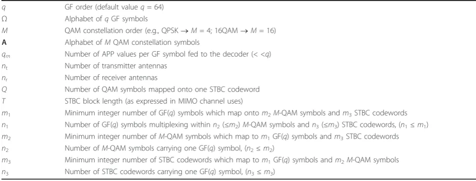
The key notations used throughout this article are listed in Table 1.
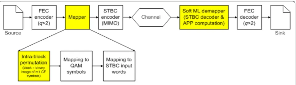
A block diagram of the non-binary transmission chain is depicted in Figure 1. In the following, we first intro-duce the non-binary LDPC codec used, and then describe the functioning of the non-binary wireless transmission chain illustrated in Figure 1.
2.1 Non-binary LDPC codes
The non-binary LDPC codes used are taken directly from DAVINCI project [4]. These codes have been designed with a very sparse parity check matrix. The non-zero elements of the matrix are defined over a GF of orderq = 64, denoted byΩ. The variable node degree is fixed todv= 2 (optimal whenq ® ∞and codeword
length® ∞), whereas the check node degreedc is
vari-able and adapted to the coding rate (i.e.,dc = {4, 6, 8,
12} for rate = {1/2, 2/3, 3/4, 5/6}, respectively). The DAVINCI codes are obtained as regular LDPC codes over the GF Ω following the optimization process described in [9]. At the receiver side, we use a reduced complexity non-binary decoder based on the Extended Min-Sum algorithm proposed in [8] for practical hard-ware implementation of the DAVINCI codes. This low complexity decoder takes only the qm (qm <q) highest
APP values out of theq - 1 values available at the out-put of the soft demapper. This truncation of the APP values at the input of the decoder reduces significantly the decoder complexity at the cost of slight performance degradation.
2.2 Non-binary wireless transmission chain 2.2.1 Transmitter operations
As illustrated in Figure 1, the binary information mes-sage issued from the source is first converted into non-binary GF(q) message by simply mapping groups of log2 (q) bits onto their corresponding GF(q) images. The
Table 1 Key notations used throughout the article
q GF order (default valueq= 64) Ω Alphabet ofqGF symbols
M QAM constellation order (e.g., QPSK®M= 4; 16QAM®M= 16) A Alphabet ofMQAM constellation symbols
qm Number of APP values per GF symbol fed to the decoder (< <q)
nt Number of transmitter antennas
nr Number of receiver antennas
Q Number of QAM symbols mapped onto one STBC codeword
T STBC block length (as expressed in MIMO channel uses)
m1 Minimum integer number of GF(q) symbols which map ontom2M-QAM symbols andm3STBC codewords
n1 Number of GF(q) symbols multiplexing withinn2(≤m2)M-QAM symbols andn3(≤m3) STBC codewords, (n1≤m1)
m2 Minimum integer number ofM-QAM symbols which map tom1GF(q) symbols andm3STBC codewords
n2 Number ofM-QAM symbols carrying one GF(q) symbol, (n2≤m2)
m3 Minimum integer number of STBC codewords which map tom1GF(q) symbols andm2M-QAM symbols
binary images are obtained from the primitive polyno-mial below used in the DAVINCI project to optimize the DAVINCI codes [4,9]:
P(x)=x6+x+ 1 (1)
Blocks of K GF(q) symbols are then passed to the non-binary LDPC encoder which generates the non-bin-ary codeword of lengthNGF(q) symbols. In order then to map the non-binary Forward Error Correction (FEC) codeword onto theM-QAM constellation symbols, each of the GF(q) symbols in the FEC codeword is first con-verted back to its binary image of log2(q) bits (using the same primitive polynomial in (1)). The resulting binary stream is then passed to the Mapping module, which is in charge of mapping the GF(q) symbols onto the M -QAM constellation symbols and STBC codewords. As highlighted in Figure 1, the mapping function features a novel module referred to as intra-block permutation
which permutes/re-arranges the bits (per block of m1 GF symbols) in the binary stream in accordance with three design rules devised in this article to achieve the trade-off between performance and complexity. Next to the intra-block permutation, each group of log2(M) adja-cent bits of the permuted output stream is mapped onto one QAM constellation symbol. A conventional gray-mapping is used to produce the stream of complex-valued QAM symbols. The QAM symbols are then directly sent for transmission over the wireless multi-path fading channel in the context of a single antenna transmission.
In the context of multi-antenna transmission, the stream of QAM symbols undergoes a further step of spatial encoding represented by the STBC encoder depicted in Figure 1. The QAM symbols are arranged in groups ofQsymbols, and each group is encoded by the STBC encoder resulting into a STBC codewordVjofnt × T complex symbols, with nt being the number of transmitter antennas andT the STBC block length. The spatial rate is then given by RS = Q/T. The output
stream of the STBC encoder is then transmitted across the multiple antennas through the multi-path fading channel.
2.2.2 Receiver operations
At the receiver side, with single antenna (i.e., single out-put), the complex-valued received signal can be modeled as:
y=hx+v (2)
where his the channel fading,xthe transmitted sym-bol per channel use, and v the background noise assumed to be complex-valued Gaussian distributed with zero mean and single-sided varianceN0.
The received symbols are de-interleaved at the QAM level, and next fed into the soft demapper, which com-putes the APP values of all GF(q) symbols in the code-word. The computation of the APP values in the non-binary case is much heavier than in the case of non-binary transmission for two reasons: first, each GF(q) coded symbol calls for the computation of (q - 1) APP values, and second the computation of each APP value turns out to be particularly complicated whenever one GF(q) symbol is spread across different QAM symbols (see Section 3 for more details). The APP values are fed into the non-binary FEC decoder, and the decoded GF sym-bols are finally converted into bits to represent the received binary message.
The received signal model is slightly more compli-cated withnt×nrMIMO transmission.
The received STBC codeword Wj of size nr ×T is a linear transformation of the transmitted STBC codeword
Vjplus additive Gaussian noiseνj, as shown below:
Wj=HjVj+νj (3)
whereHjis annr×ntcomplex matrix representing the MIMO frequency-flat channel coefficients for thejth STBC codewordVj.
The received STBC codewords are fed into the so-called Soft Maximum Likelihood (ML) demapper which
combines the STBC ML detection and the APP compu-tation. It is noteworthy here that sub-optimal linear equalizers may be considered for the STBC detection, which will then be followed in a second step by the APP computation for non-binary LDPC decoder. Such linear approach was compared to the soft ML demapper in [4,10], where the latter was shown to significantly out-perform the former. It is not in the scope of this article to reproduce such comparison, but rather focus on the complexity reduction of the soft ML demapper with the aim to make it practical for wireless communication systems.
3. Problem statement: mapping and Soft ML demapping
Figure 2 illustrates the different stages for mapping the GF(q) non-binary symbols onto the M-QAM constella-tion symbols, and later on onto the STBC codewords should MIMO transmission be considered.
3.1 Mapping of GF(q) symbols ontoM-QAM symbols
As suggested in [6], in order to ensure a bijective map-ping between GF(q) and M-QAM symbols, we have to map a vector of m1 GF(q) symbols onto a vector ofm2
M-QAM symbols, such that both vectors are of the same length as expressed in (coded) bits:
m1×log2
q=m2×log2(M) (4)
In [6], in order to minimize the complexity of the mapper and demapper, the parametersm1 andm2 are
set to their minimum possible integer values in accor-dance with Equation (4). Assumingq = 64, Table 2 lists the values of m1 and m2 to be used with QPSK, 16QAM, and 64QAM constellations.
For example for QPSK, one GF(64) symbol maps onto three QPSK symbols. For 16QAM however, two GF(64) symbols will map onto three 16QAM symbols, and con-sequently two GF(64) symbols will be spread onto at least one 16QAM symbol. For 64QAM, the mapping is obviously one-to-one since both GF(64) and 64QAM symbols are represented by the same number of bits (= log2(64) = 6).
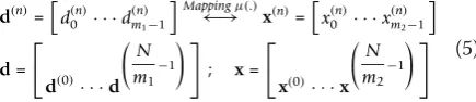
The mapping between GF(q) symbols and M-QAM symbols can be formulated as:
d(n)=d(n)0 · · ·d(n)m1−1
Mappingμ(.)
←→ x(n)=x(n)0 · · ·x(n)m2−1
d=
d(0)· · ·d ⎛
⎝N
m1−1 ⎞ ⎠
; x=
x(0)· · ·x ⎛
⎝N
m2−1 ⎞ ⎠
(5)
In the sequel, we consider only one vector d(n) and corresponding vector x(n), and omit the superscript indexn for the sake of simplicity. Thus,d andx refer now to two vectors of lengthsm1and m2, respectively, associated by the mapping function μ(.). As illustrated in Figures 1 and 2, the mapping functionμ(.) features a novel component introduced in this article which is the so-called“intra-block permutation“. In this component, the bits in the binary image of the vector of m1 GF(q) symbols are permuted (re-arranged) in accordance with the design rules proposed in Section 3.1. This is with
the aim to achieve the best trade-off between perfor-mance and complexity.
At the receiver side, the soft demapper computesq- 1 APP values for each GF(q) coded symbol. For a mem-oryless SISO channel and assuming all GF(q) coded symbols are equiprobable, we can write thekth (k= 0...q
(2), hj is the corresponding equivalent channel
coeffi-cient (that we assume perfectly known), xj=μj(d) the jth entry in the vectorx of m2 QAM symbols mapping onto the vectordofm1 GF(q) symbols, andνjthe noise
term. The set k
i includes all configurations of vectord
withith componentdi =ak, whereakdenotes the kth
entry in the GF Ω. The cardinality of k
i is clearly
equal toqm1-1.
The computational complexity of the soft demapper is of a magnitude order O((q - 1) × qm1-1× m2) per GF symbol. This reflects an exponential growth with the GF order q whenever the minimum number m1 of GF(q) symbols that are spread onto M-QAM symbols is strictly greater than 1 (m1 > 1). This is the case with 16QAM as given in Table 2.
3.2 Mapping of GF(q) symbols onto STBC codewords
With MIMO transmission, a number Q of M-QAM constellation symbols (equal to one input word to the STBC encoder which outputs once corresponding STBC codeword) are encoded together and transmitted across
nttransmitter antennas duringT transmission intervals (also known as MIMO channels uses). Thus, similarly to (4), we have to map here the original vector of m1 GF (q) symbols (mapping onto the vector ofm2 M-QAM symbols) onto a third vector of m3 STBC codewords, such that all three vectors are of the same length in bits:
m1×log2
q=m2×log2(M)=m3×Q×log2(M) (7)
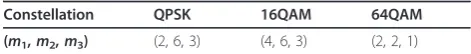
The parametersm1, m2, andm3 should be set to their minimum possible integer values in accordance with
Equation (7). Assumingq = 64, STBC codeword sizeQ
= 2, Table 3 gives the values of m1, m2, and m3, with QPSK, 16QAM, and 64QAM constellations.
Compared to Table 2, the values of m1 and m2 in Table 3 are simply doubled as a result of MIMO trans-mission withQ= 2. For a memoryless MIMO channel, we can write the kth (k= 0...q - 1) APP value (assuming the to use Log-MAP) for the ith (i = 0...m1 - 1) GF(q) coded symbol in the vector d of m1 GF(q) symbols mapped onto the vector of m2 QAM symbols (equiva-lent tom3 STBC codewords) as
λi,k= ln
whereSM(.) denotes the MIMO encoder operation, which encodes the stream of QAM symbols into STBC codewords, and ..F is the Frobenius norm. The para-metern3is defined in Table 1 as the number of STBC codewords carrying one GF(q) symbol (n3 ≤m3). The value ofn3may then vary from one GF symbol to another in the vector ofm1GF symbols and therefore depends on the indexiof the GF(q) symbol. The vectordmay thus have different bit lengths depending on whether n3 is equal to or greater than 1. Furthermore, in order to mini-mize the computational weight of the APP extraction, we can exploit the max-Log-MAP, so that (8) becomes the difference between the maximum sum at the numerator and the maximum sum at the denominator.
Taking into account the inherent matrix multiplica-tion required to compute the distance between STBC codewordsVj and Wj (cf. (3)), the computation
com-plexity of the soft demapper becomes of the magnitude order O((q- 1) ×qm1-1×m3 ×nr×Q×T). Whenm1> 1 different GF(q) are spread into different STBC code-words, and this occurs here for any constellation, unlike the SISO case where it only occurs for 16QAM constel-lation (cf. Table 2). This emphasizes how problematic the complexity of the soft demapper may become with MIMO transmission, even with simple practical config-urations (e.g.,Q= 2). The main problem tackled in this article is the reduction of the complexity of the soft demapper when one GF(q) symbol spreads across differ-ent QAM symbols and STBC codewords (i.e.,m1 > 1), without sacrificing the error protection performance. Table 2 Values ofm1andm2for GF(64) to QAM mapping
4. Novel mapping strategy and low complexity soft demapping
Our solution to the problem stated above consists of a mapping strategy at the transmitter side together with an algorithm for low complexity soft demapping when one GF(q) symbol spreads across different QAM sym-bols and STBC codewords (i.e.m1> 1).
4.1 Mapping strategy at the transmitter
Three rules are introduced hereafter with the aim to achieve the best trade-off between error protection per-formance and soft demapper complexity.
First rule: The I or Q component of an M-QAM symbol should carry (in part or in full) the binary image of only one GF(q) symbol
This rule naturally applies to the particular case ofm1= 1, and can always be met whenever the number of bits per GF(q) symbol log2(q) is an integer multiple of the number of bits perIorQcomponent log2(M)/2. Other-wise, the rule requires mapping as manyIandQ com-ponents as possible to binary parts issued from the binary image of only one single GF symbol. This ensures better performance compared to all other schemes not obeying to this rule, as will be proven in Section 5.
Assuming SISO 16QAM with m1 = 2 and m2 = 3, Table 4 gives four possible patterns to map the two GF (64) symbols a and b with binary images respectively,
a0a1a2a3a4a5 andb0b1b2b3b4b5, onto the three 16QAM symbols with IandQcomponents,I0Q0,I1Q1, andI2Q2. Amongst the four patterns shown in Table 4, only P1
andP3obey the first rule.
Second rule: Map as many I/Q components as possible issued from the same GF(q) symbol onto the same STBC codeword
This will ensure a minimum number (n3 ≤m3) of STBC codewords to be considered by the soft demapper for the computation of the APP values of each GF(q) sym-bol, and so will contribute to the reduction of the com-plexity of soft ML demapping as proposed in Section 4.2, but to the detriment of limiting the maximum chan-nel selectivity that can be achieved within one GF(q) symbol. This is because ideally by letting each I orQ
component issued from one GF(q) symbol map onto different STBC codewords, we create higher chance for
these parts of the same GF(q) symbol to experience uncorrelated channel fading. This rule clearly restricts the freedom to let the GF(q) symbol enjoy higher chan-nel selectivity, but fortunately has the advantage of redu-cing drastically the complexity of the soft ML demapper. This is where the complexity of the soft ML demapper is traded off with the error protection performance of the GF(q) symbols.
Third rule: Under the constraint of the second rule, map the I/Q components issued from one GF(q) symbol onto the transmission units ideally of independent channel fading within the STBC codeword carrying this GF(q) symbol
This rule obviously targets the maximum achievable channel selectivity (i.e., number of independent channel fading) within each GF(q) symbol under the constraint of the second rule. The higher the channel selectivity within one GF(q) symbol is (i.e., the number of indepen-dent channel fading affecting the different parts of the GF(q) symbol), the better the error protection perfor-mance is expected to be. The margin for this rule to achieve higher channel selectivity order is clearly bound by the second rule.
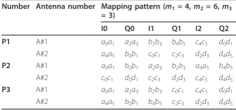
For example, in the case of MIMO uncoded spatial multiplexing (Q= 2) and 16QAM where m1 = 4,m2 = 6, and m3 = 3 (cf. Table 3), we give in Table 5 three possible patterns for mapping the four GF(64) symbols,
a, b, c, and d, of binary images, respectively,
a0a1a2a3a4a5, b0b1b2b3b4b5,c0c1c2c3c4c5,d0d1d2d3d4d5, onto the six 16-QAM symbols representing three STBC codewords. Each STBC codeword carriesQ= 2 16QAM symbols concurrently transmitted over 2 antennas.
All three patterns in Table 5 follow the first rule by not mixing bits from different GF symbols into the same I or Q component.
PatternsP1 and P3 further obey the second rule by mapping as many I/Qcomponents from the same GF symbol as possible into the same STBC codeword, whilst PatternP2does not. For patternsP1andP3, GF (64) symbols a and d are carried within one single STBC codeword, and GF(64) symbols b and c are mapped onto two STBC codewords. However, for
Table 4 Example of four patterns for mapping GF(64) symbols to 16-QAM symbols
patternP2, each GF(64) symbol is spread out over all of the m3= 3 STBC codewords. In terms of complexity of the soft demapper, patterns P1 and P3 will enable reduced complexity, whereas the complexity with pat-ternP2will be drastically higher, as shown later in Sec-tion 4.2.
Now with regard to the third rule, the channel selec-tivity order (i.e., maximum number of independent channel fading) for pattern P1 is equal to 2 for all GF symbols,a,b,c, andd. This is clear since any of these GF symbols is mapped onto exactly two QAM symbols within only one single STBC codeword, with the first QAM symbol transmitted on the first antenna port and the second QAM symbol transmistted on the second antenna port. For pattern P2 however, the channel selectivity order is higher and equal to 3, since any GF symbol is mapped onto exactly three QAM symbols transmitted within three different STBC codewords, hence ideally subject to three independent channel fad-ing. The last pattern P3 has its channel selectivity order equal to 2 for the edge symbols aand d (since carried in two QAM symbols within one single STBC code-word), whereas it is equal to 3 for the middle symbolsb
and c (since these are carried in two QAM symbols within two STBC codewords). Amongst all three pat-terns, only P1 and P3 respect the second rule, but only P3 which further respects the third rule as it attempts to achieve the highest possible channel selectivity order under the constraint of the second rule.
In summary, by obeying all the three rules introduced above, we aim to obtain mapping patterns which ensure the best trade-off between performance and complexity. This will be further detailed and proven in Sections 4.2 and 5.
4.2 Low complexity soft demapping at the receiver
As highlighted in Equation (6), the soft demapper at the receiver requires two major steps for the computation of the APP values of the GF(q) coded symbols: (i) Eucli-dean distances computation, and (ii) Marginalization across all possible combinations. The Euclidean dis-tances computation is typically required for ML hard detector. In our case, since soft values are required, the MIMO ML detection and non-binary soft demapping are combined together into one single function, referred to as soft ML demapping.
First step: Computation of the Euclidean distances
In the decoding of STBC, each received STBC codeword
Wjis processed individually in order to obtain its
dis-tance to all possible transmitted STBC codewordsVj. In
our non-binary case (q > 2), one GF(q) coded symbol may span more than one STBC codeword. Thus, for the computation of the APP values of one GF(q) symbol, there is a need to store the Euclidean distances of all of
the STBC codewords which carry the binary image of the given GF(q) symbol. Thanks to our second rule in the design of the mapper at the transmitter (which lim-its the number of STBC codewords carrying the binary image of one GF(q) symbol to the minimum possible), only the Euclidean distances of n3 ≤ m3 STBC code-words are needed. This clearly reduces the memory requirements at the receiver.
Second step: Marginalization across all possible combinations
The marginalization takes the form of a summation in the general case (i.e.. log-Map) reflected in Equation (6). Should the Max-log approximation be used, it takes instead the form of a comparison. The marginalization (or summation) involves the Euclidean distances ofn3 ≤
m3 STBC codewords and the binary sub-parts of then1 - 1 (n1 ≤m1) GF(q) symbols multiplexing with the bin-ary image of the desired GF(q) symbol in their mapping to the n2 ≤ m2 M-QAM symbols and n3 ≤ m3 STBC codewords.
For the sake of simplicity, let us consider first the case wheren3 = 1, i.e., the desired GF(q) symbol is mapped onto a single STBC codeword. This is the case of SISO transmission but also applies for instance to MIMO transmission for the edge GF(q) symbolsaandd in pat-terns P1 and P3 in Table 5. Let us focus first on the simple case of SISO transmission with 16QAM as in Table 4 with the straightforward mapping P1 = [a0a1a2a3]; [a4a5b0b1]; [b2b3b4b5]; for m1= 2 andm2 = 3. In order to compute the APP values for the first GF (64) symbola, the Euclidean distances involving the first
n2 = 2 ≤3 QAM symbols are required. For the second GF(64) symbol b, those involving the second and the third QAM symbols are required. For the computation of the APP values of a, a marginalization is required across all of the possible combinations of the sub-part
b0b1 from GF(64) symbol b due to their mix with the sub-part a4a5 in the second QAM symbol (i.e., [a4a5b0b1]). The number of all possible combinations is clearly equal to 22 = 4. The number of operations per received GF symbol is (q- 1) × 22× 3, a factor 22/qm1-1
= 4/64 = 1/16 smaller than the value O((q- 1) × qm1-1
× m2) indicated earlier in Section 3.1. Thanks to the specific mapping where the two edge 16QAM symbols carry information from only one single GF(64) symbol. Similar marginalization is required in the second case of MIMO transmission for the edge GF(q) symbolsa and
din patterns P1and P3in Table 5.
across all the possible combinations ofa0a1a2a3a4a5 due to the mix with the sub-part b0b1 in the first STBC codeword, and also across all of the possible combina-tions of c0c1c2c3 due to the mix with the sub-part
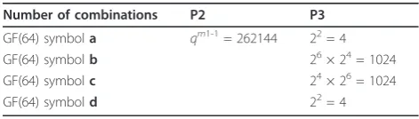
b2b3b4b5 in the second STBC codeword. This adds up to the total of 26 × 24 = 1024 combinations per APP value. Demapping complexity clearly depends on the mapping pattern used. Table 6 gives an example of the number of distances required for marginalization of each APP value for the two mapping patterns P2 and
P3from Table 5.
Table 6 reflects the huge complexity incurred with mapping pattern P2 (although as said earlier, this pat-tern achieves the maximum transmit diversity order 3 for all the GF(64) symbols). This confirms the tremen-dous complexity advantage of the mapping patterns respecting the second rule devised previously. Yet, whilst only 4 combinations are required for the edge symbolsa
andd, 1024 combinations are required for the symbols in the middle b and c, which is still relatively a high number.
Still, 1024 is a relatively large number causing exces-sive complexity. To further reduce the number of com-binations to a relatively low level, we propose the following algorithm which exploits the correlation exist-ing between GF(q) symbols produced by the code. The algorithm introduces a threshold parameter calledNm.
The algorithm proceeds with the following steps:
• Step 1:Set the value ofNm. For example,Nmis set
to the value 8.
• Step 2:For any GF(q) symbol entailing a number
Ne of combinations required for marginalization
lower than the threshold Nm, obtain the
correspond-ing APP values uscorrespond-ing an exhaustive search over all
Nerequired combinations.
○Example: This applies to the edge symbols a
anddin P1andP3in Table 5, where the num-ber of combinations required isNe= 4 <Nm= 8.
• Step 3:For GF(q) symbols that multiplexonlywith
symbols falling under step 2, compute the APPs by limiting the combinations associated with the GF(q) symbol from step 2 only to the ones yielding theNm largest APPs for this symbol.
○ Example:Assume we are transmitting three
consecutive GF(256)*symbolsa,b, andgmapped onto two consecutive 64-QAM STBC codewords. Then symbols a and g fall under Step 2, while the APPs forb have to be computed as above. Assuming Nm = 16, then the marginalization
over aand bwill be carried out by considering only Nm · Nm = 256 terms instead of the 256 ·
256 = 65536 terms in the exhaustive search.
*NB: Switching to GF(256) in this example is sim-ply because no such case occurs with our default GF(64).
•Step 4:For each remaining GF(q) symbol, not
fall-ing under steps 2 and 3, proceed with the followfall-ing sub-steps:
○ Step 4.1:Limit the combinations associated
with the multiplexing GF(q) symbol from step 2 to the ones yielding the Nm maximum APP
values for this multiplexing symbol.
○Step 4.2:Complete the marginalization of the
APPs with respect to the adjacent GF(q) symbol whose APPs are still unavailable with an iterative procedure for a number r of iterations and depending on a parameterNq. At ith iteration,
the marginalization runs across theNq
combina-tions of the interleaved symbol with the highest
Nq APP values. Such combinations are those
computed in the previousi - 1 iteration of the algorithm. At the initialization stage, the Nq
combinations are chosen randomly.
○Example:Step 4.1 applies to the middle GF(q) symbol bin P1 andP3 in Table 5, where mar-ginalization is required across the interleaved edge GF(q) symbol a. The APP values of the edge symbol a are obtained from step 2. Thus, instead of searching over all the 26= 64 possible values of symbol a, we only limit the search to theNm= 8 values of symbolayielding the
high-est APP values (thus 8 highhigh-est likelihood values). Step 4.2 applies to the middle GF(q) symbolbin
P1 andP3 in Table 5, where marginalization is required across the interleaved other middle GF (q) symbolc, whose APP values are not available from step 2. We start considering Nq = 8
ran-domly selected APP values for symbolc(out of the 24 = 16 values theoretically needed) to obtain the (marginalized) APP values of symbol b. Then, we compute the APP values for symbolsb
andc, with the marginalization limited to the Nq
random values of each. We refine then the choice of theNq combinations used for
margina-lization to the ones yielding the highestNq APP
values for symbolsbandc. This is repeated forr
iterations. Table 6 Example of number of combinations to be
considered for APP marginalization
Number of combinations P2 P3
GF(64) symbola qm1-1= 262144 22= 4
GF(64) symbolb 26× 24= 1024
GF(64) symbolc 24× 26= 1024
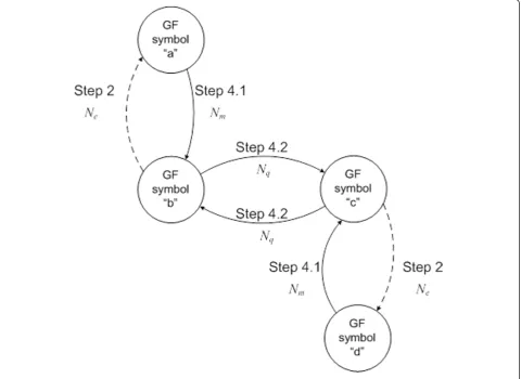
The above algorithm may better be illustrated with the graph depicted in Figure 3, where the nodes represent the computation of the APP values for each GF symbol, and the arrows indicate the propagation of the most likely combinations of one GF symbol at a given node to the GF symbol at an adjacent node. This for the pur-pose of reduced marginalization according the different steps described in the above algorithm. The edge sym-bols a andd fall under step 2 and will therefore get their APP values available simply from step 2. The mid-dle symbolsbandcmake use ofNmmost likely
combi-nations yielding the highest APP values for the eddge GF symbols a andd, respectively. The propagation of these combinations is illustrated in Figure 3 by the arrows coming into nodes b(from nodea) andc(from node·d). Since symbolsbandcmultiplex together, then an iterative process as described in step 4.2 is followed by reusing theNqmost likely combinations of one
sym-bol for marginalization to obtain the APP values of the adjacent symbol. This exchange of Nq combinations
between GF symbolsbandcis illustrasted in the graph by the arrows connecting nodesbto c. Although in the
example the same value (equal to 8) is set for both numbers Nmand Nq, this does not reflect the general
case where these two variables can be set with different values.
The introduction of the variablesNmand Nq taking
values much lower than the total numberqof the APP values is mainly inspired from the work originally done by the authors in [8,11] in their contribution to the FP7 DAVINCI project [4]. The authors of [8,11] have con-ducted a thorough analysis of the behavior of the non-binary LDPC decoder specifically in term of the APP distribution of the GF symbols at the input of the LDPC decoder. The main motivation in [8] is the proposal of sub-optimal LDPC decoding algorithm of reduced com-plexity and less memory requirements for real imple-mentation. A key result found in [8,11] is that by feeding the non-binary LDPC decoder with only a lim-ited number Nmof the highest APP values for each GF
symbol (with Nm much less than the GF order q)
achieves very close to the optimal performance whilst reducing significantly the non-binary LDPC decoding complexity and APP memory requirements. This finding
is borrowed in our algorithm above to reduce the com-plexity challenge of the soft ML demapper.
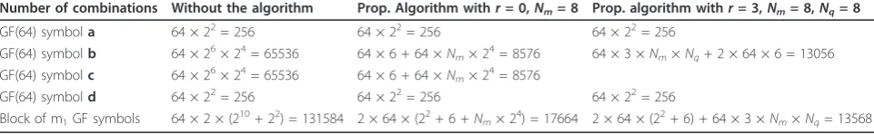
Table 7 reports the number of combinations to be explored for extracting theq-ary APP values of each GF (64) symbol first without the low complexity algorithm and then for two settings of the low complexity algo-rithm. When the low complexity algorithm is selected, GF(64) symbolsband crequire first a number of opera-tions for sorting the APP values of GF(64) symbols a
andd, respectively. The implemented algorithm, which is based on Merge and Sort approach, has a complexity of n·log(n) (with n being the length of the vector to sort). The proposed algorithm reduces the number of combinations used for marginalization to obtain the APP values of the middle symbolsbandcby a factor of approximately 7.5 without iterations, and a factor of approximately 10 with 3 iterations. The impact of the proposed algorithm on the error performance is assessed in Section 5.
5. Numerical results
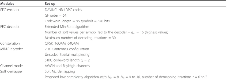
Table 8 summarizes the simulation set up that was used to derive performance results. Both a SISO and a MIMO scenario are considered as representative of next generation cellular communication systems.
Figure 4 depicts the Frame Error Rate (FER) results obtained in the SISO scenario using two different pat-terns to map the GF(64) symbols onto QAM constella-tion symbols. The first mapping is an arbitrary mapping which does not respect the first rule devised in our solu-tion, whereas the second mapping referred to as opti-mum mapping does.
As illustrated in Figure 4, for QPSK and 64QAM, wherem1= 1 (cf. Table 2), there is no significant differ-ence between the arbitrary and the proposed mapping patterns, since inherently here only one GF(64) symbol maps onto three QPSK symbols or one 64QAM symbol. However, for 16QAM, where m1 = 2 and m2 = 3 (cf. Table 2), two GF(64) symbols are mapped onto the same mapping onto one 16QAM symbol, and here the results show clear SNR gain of 0.5 dB for the mapping respecting the first design rule as compared to a pattern not respecting this rule, hence validating the merits of this rule. It is noteworthy here that at this stage, there is no issue of trade-off between performance and
complexity (this will come later when considering the second and third design rules proposed).
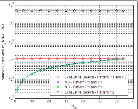
We then move to the MIMO context in order to vali-date the second and third rules introduced in our map-ping strategy, which aim to achieve a trade-off between performance and complexity. First we analyze the com-plexity in terms of number of operations of the APP extraction. Specifically, with the termoperationwe refer to a summation or a comparison of real-valued num-bers, so either the summation or comparison operation has the same computational weight. We consider first the case of 16QAM with the three patterns given in Table 5, where patterns P1 and P3 respect the second rule, but not pattern P2. Figure 5 depicts the number of operations required for marginalization in the computa-tion of the APP values of the m1 = 4 GF(64) symbols which map together onto m2= 6 QAM symbols andm3 = 3 STBC codewords. Four curves show the number of operations (in logarithm scale) as a function of the threshold Nm introduced in the proposed algorithm.
The curves are as follows:
•The first curve in black circular marker gives the number of operations when an exhaustive search with pattern P2 is performed.
•The second curve in red circular marker gives the number of operations when an exhaustive search with pattern P1 or P3 is performed.
•The third curve in blue downwards triangular mar-ker shows the number of operations using the pro-posed algorithm without the iterative step 4 (i.e., simply replace sub-step 4.2 by an exhaustive search). •The fourth curve in green with diamond markers considers the iterative step 4 of the proposed algo-rithm withr = 3 iterations andNq= 10.
From Figure 5, we can first clearly appreciate the huge reduction in complexity (cf. gap between first curve using P2, and the other curves using P1 and P3). This clearly validates the merit of our second rule from the complexity perspective, where patterns P1 and P3 respect this second rule, but not pattern P2. Moreover, from Figure 5, we can also clearly appreciate the signifi-cant reduction in complexity (cf. gap between second curve, and third and fourth curves) brought by the use
Table 7 Example of reduction of the number combinations for P1 and P3 from Table 6
of the proposed algorithm (with and without iterations) as compared to the exhaustive search. The reduction in complexity clearly decreases when increasing the thresh-oldNm. For a typical value ofNm= 8, we can appreciate
nearly one decay (i.e., a factor of 10) complexity reduc-tion; thanks to the proposed algorithm.
The second aspect to be assessed here is the impact of the proposed mapping strategy and demapping
algorithm on the error protection performance. This is illustrated in Figure 6, for patterns P1 and P3 with dif-ferent configurations. It is worth noting here that the pattern P2 could not be evaluated since its breach of the second rule makes it non practical for computer simula-tions. Our reference curves are the ones in red solid line which perform an exhaustive search (i.e., do not imple-ment the proposed algorithm). In this figure, square Table 8 Simulations set up
Modules Set up
FEC encoder DAVINCI NB-LDPC codes GF order = 64
Codeword length = 96 symbols = 576 bits FEC decoder Extended Min-Sum algorithm
Number of soft values per symbol fed to the decoder =qm= 16 (highest values)
Maximum number of decoding iterations = 30 Constellation QPSK, 16QAM, 64QAM
MIMO encoder 2 × 2 antennas configuration Uncoded Spatial multiplexing STBC codeword lengthQ= 2 Channel model AWGN and Rayleigh channels Soft demapper Soft ML demapping
Proposed low complexity algorithm withNm= 8,Nq= 4 to 16, number of demapping iterationsr= 0 to 3
marker is used for mapping pattern P1, and circular marker for mapping pattern P3.
From Figure 6, we first compare the performance gap between patterns P1 and P3 with the exhaustive search used in both. This is in order to appreciate the trade-off in performance due to the second rule and the merits of the third rule. The performance gap between P1 and P3 is almost 0.25 dB, when P1 has a constant channel selectivity order equal to 2 and P3 has an average chan-nel selectivity order equal to 2.5 (it is equal to 2 at the edge symbols and 3 at the middle symbols). As men-tioned previously, both patterns P1 and P3 respect the second rule, but only P3 respects the third rule. Hence, from this comparison, the merit of the third rule is clearly appreciated (approximately 0.25 dB SNR gain) at the same level of complexity. The same performance gap is expected between patterns P2 and P3 (although as said before simulations with pattern P2 are not feasi-ble since it breaches the second rule). This expectation
is motivated by the fact that the gap in channel selectiv-ity order between P2 and P3 is equal to 0.5, which is the same gap between P3 and P1 (PS: the average chan-nel selectivity order is equal to 3, 2.5, and 2, respec-tively, for patterns P2, P3, and P1). Hence, the penalty in performance of the second design rule is expected to be around 0.25 dB, compared to a pattern P3 respecting the second and third design rules, and 0.5 dB compared to a pattern P1 respecting the second rule but not the third rule.
Now let us compare the performance of both patterns P1 and P3 when using the proposed soft demapping algorithm. From Figure 6, for both patterns P1 and P3, we do not notice any appreciable degradation when using the proposed algorithm with threshold Nm = 8,
and without using the iterative process, compared to when using the exhaustive search. This is an important result as it shows the potential of the proposed algo-rithm to reduce the complexity by tenfold without
practical degradation in the FER performance. Further reduction of the complexity by means of the iterative process for example, does degrade the FER performance. The degradation of the iterative process in the waterfall region at target FER of 10-2 appears tolerable (up to 0.5 dB), whilst the degradation in the error floor region appears significant. This reflects the trade-off someone can obtain between FER performance and further reduc-tion of the complexity with the iterative process.
Further analysis was carried out for the case of MIMO 64QAM. In such a case, we consider two different map-ping patterns as illustrated in Table 9.
Both P1 and P2 respect the first and second rule, but only P2 respects the third rule. With 64QAM, the posed algorithm must necessarily use the iterative pro-cess, since there are no edge symbols falling under step 2 of the proposed algorithm. Similarly to the 16QAM case, the sorting of the APP values should be taken into
account in the computation of the complexity. Table 10 shows a complexity reduction of 35% with respect to the exhaustive search when Nq is equal to 24 and 44%
whenNq is equal to 20.
Figure 7 also shows the FER performance results for both patterns with and without the proposed algorithm in the configurations given in Table 10. A circle marker is used for the curves with pattern P1 and square mar-ker for the curves with pattern P2.
Table 9 Used patterns for mapping GF(64) symbols to STBC codewords (64QAM)
Number Antenna number Mapping pattern (m1= 2,m2= 2,m3 = 1)
I0 Q0
P1 A#1 a0a1a2 a3a4a5
A#2 b0b1b2 b3b4b5
P2 A#1 a0a1a2 b0b1b2
A#2 a3a4a5 b3b4b5
Table 10 Example of reduction of the number combinations for 64QAM
Number of combinations Without the algorithm Prop. algorithm withr= 3,Nq= 20 Prop. algorithm withr= 3,Nq= 24
GF(64) symbola 64 × 26= 4096 64 × 3 ×Nq+ 2 × 64 × 6 = 4608 64 × 3 ×Nq+ 2 × 64 × 6 = 5376
GF(64) symbolb 64 × 26= 4096
Block of m1GF symbols 2 × 64 × (26) = 8192 64 × 3 ×Nq+ 2 × 64 × 6 = 4608 64 × 3 ×Nq+ 2 × 64 × 6 = 5376
From Figure 7, we can first appreciate a gain of nearly 0.8 dB for pattern P2 as compared to P1. This confirms further the potential of the third rule in achieving much higher diversity. Second, with pattern P2, we can clearly appreciate a slight degradation in performance nearly 0.2 dB when using the proposed low complexity iterative demapping algorithm with Nq = 24 (35% complexity
reduction). The degradation becomes higher 0.5 dB for
Nq= 20 (44% complexity reduction). So clearly, there is
a trade-off between the tolerable FER performance degradation and the target complexity reduction, and the proposed mapping strategy and low complexity demapping algorithm provide the tools to achieve the trade-off desired.
6. Conclusions
In this article, we have addressed the particular com-plexity challenge of the soft ML demapping faced with non-binary LDPC codes when one GF(q) symbol spreads across multiple QAM symbols and STBC code-words. A solution is proposed combining a mapping strategy based on three design rules at the transmitter, and a low complexity soft ML demapping algorithm at the receiver.
At the transmitter side, the mapping strategy intro-duced three design rules to achieve the best trade-off between performance and complexity. In the first rule, the I or Q component of an M-QAM symbol should carry (in part or in full) the binary image of only one GF(q) symbol. This rule was shown to bring an SNR performance gain of approximately 0.5 dB compared to mapping patterns not respecting this rule. In the second rule, theI/Qcomponents issued from one GF(q) symbol are carried into the minimum possible number of STBC codewords. This second rule clearly restricts the free-dom to let the GF(q) symbol enjoy higher channel selec-tivity, but fortunately has the advantage of reducing drastically the complexity of the soft ML demapper. In the third rule, theI/Qcomponents issued from one GF (q) symbol are mapped onto the transmission units which ideally can experience independent channel fad-ing within the STBC codeword carryfad-ing this GF(q) sym-bol. This third rule aims at exploiting the last degree of freedom left by the binding second rule to achieve high channel selectivity within the GF(q) symbol. With map-ping patterns respecting the second rule, it was shown that a tenfold complexity reduction can be achieved compared to patterns not respecting this second rule. The trade-off in performance was shown to be small, 0.25 and 0.5 dB performance degradation for the pat-terns respecting the second rule with and without the third rule, respectively.
At the receiver side, an algorithm was proposed to reduce the complexity of the soft ML demapper. The
algorithm exploits the correlation existing between GF (q) symbols but also any knowledge available on the APP values of the GF(q) symbols in the vector ofm1GF (q) symbols, which map together onto the vector of m2
M-QAM symbols and further on onto the vector ofm3 STBC codewords. The algorithm also considers only a limited number of potential combinations for each GF (q) symbol, those associated with this same limited number of highest APP values for this symbol. This lat-ter consideration has been inspired from the original work done by the authors of [8,11] to reduce the com-plexity of the non-binary LDPC decoder. Our proposed algorithm was shown to further reduce the complexity of the soft ML demapper by up to 85%.
The proposed solution mitigates the complexity chal-lenge at the receiver faced with non-binary LDPC codes when one GF(q) symbol spreads across multiple QAM constellation symbols and STBC codewords, at the expense of a slight performance degradation but not sacrificing the performance merits of non-binary LDPC codes. This removes any restriction on the size of the GF order, QAM constellation order, and MIMO scheme, whilst preserving the merits of non-binary LDPC codes at very reasonable receiver complexity. Future work will be focused on the assessment of the MIMO schemes which are best suited for combination with GF(64) non-binary LDPC codes, with the ultimate goal of proposing non-binary LDPC codes for beyond 4 G wireless communication systems.
Acknowledgements
This study was supported by INFSCO-ICT-216203 DAVINCI“Design And Versatile Implementation of Non-binary wireless Communications based on Innovative LDPC Codes”http://www.ict-davinci-codes.eu funded by the European Commission under the Seventh Framework Programme (FP7) [4].
Author details
1Samsung Electronics Research Institute, South Street, Staines, TW18 4QE, UK 2
Dip. Ing. Informazione, University of Pisa, via Caruso 16, 56122 Pisa, Italy
Competing interests
The authors declare that they have no competing interests.
Received: 27 April 2011 Accepted: 20 February 2012 Published: 20 February 2012
References
1. M Davey, DJC MacKay, Low density parity check codes over GF(q). IEEE Commun Lett.2(6), 165–167 (1998). doi:10.1109/4234.681360
2. J Huang, J Zhu, Linear time encoding of cycle GF(2p) codes through graph analysis. IEEE Commun Lett.10(5), 369–371 (2006). doi:10.1109/
LCOMM.2006.1633326
3. D Declercq, M Fossorier, Decoding algorithms for non-binary LDPC codes over GF(q). IEEE Trans Commun.55(4), 633–643 (2007)
4. INFSCO-ICT-216203 FP7 DAVINCI project, http://www.ict-davinci-codes.eu 5. I Gutierrez, Final proposal for IMT-Advanced systems. FP7 DAVINCI
deliverable D2.1.4 (2009)
7. F Guo, L Hanzo, Low complexity non-binary LDPC and modulation schemes communicating over MIMO channels, inProceedings of IEEE VTC, Los Angeles (USA), 1294–1298 (September 2004)
8. E Boutillon, L Conde-Canencia, Bubble check: a simplified algorithm for elementary check node processing in extended min-sum non-binary LDPC decoders. IET Electron Lett.46(9), 633–634 (2010). doi:10.1049/el.2010.0566 9. C Poulliat, M Fossorier, D Declercq, Design of regular (2, dc)-LDPC codes
over GF(q) using their binary images. IEEE Trans Commun.56(10), 1626–1635 (2008)
10. O Picchi, A Mourad, I Gutierrez, M Luise, On the performance of non-binary LDPC with MIMO in practical systems, inIEEE International Symposium on Wireless Communication Systems (ISWCS)(Aachen (Germany), 452–456 (6–9 November 2011)
11. A Singh, A Al-Ghouwayel, G Masera, E Boutillon, A new performance evaluation metric for sub-optimal iterative decoders. IEEE Commun Lett. 13(7), 513–515 (2009)
doi:10.1186/1687-1499-2012-55
Cite this article as:Mouradet al.:Low complexity soft demapping for
non-binary LDPC codes.EURASIP Journal on Wireless Communications and
Networking20122012:55.
Submit your manuscript to a
journal and benefi t from:
7Convenient online submission 7Rigorous peer review
7Immediate publication on acceptance 7Open access: articles freely available online 7High visibility within the fi eld
7Retaining the copyright to your article