Available online: https://edupediapublications.org/journals/index.php/IJR/ P a g e | 902
Advanced Vehicle Security System with Theft Control and Accident
Notification Using Gsm and Gps Technology
Meda.Saikrishna
1,Karri.Mohansesha Reddy
2,Ala.Suresh Babu
3,
1,2,3
Student,
Department of Electronics and Communication Engineering,
Lakireddy Balireddy College of Engineering, Mylavaram, Andhra Pradesh, India
Abstract
:
The system permits localization of the automobile and transmitting the position to the owner on his mobile phone as a short message (SMS) at his request. This system is also provided with emergency switch which can be turned off through an SMS. This switch takes the responsibility to turns OFF the engine. This Project presents an automotive localization system using GPS and GSM SMS services. This system requires the combination of AT89S52 microcontroller, GSM, GPS, IR sensors, Motor, Power supply, Vibration sensor, LCD Display
This can be interconnected with the car alarm system and alert the owner on his mobile phone. This tracking system is composed of a GPS receiver, Microcontroller and a GSM Modem. GPS Receiver gets the location information from satellites in the form of latitude and longitude. The Microcontroller processes this information and this processed information is sent to the user/owner using GSM modem.
In case of vehicle theft situations the owner can know the vehicles current location and based on that he can stop the vehicle by sending a predefined SMS message to this system. After receiving SMS message from owner this system automatically stops the ignition system hence the vehicle will not function any more. If an unknown person tries to access your car, here it was provided with a special feature of sending an sms to owner of vehicle as a security alert when someone tries to access your vehicle.
The tracking of the vehicle can be done from any location at any time. In case of any accidents occurred to vehicle, This system immediately sends a notification to the family person and police station and to hospital.
The presented system application is a low cost solution for automobile position and status, very useful in case of car theft situations, for monitoring adolescent drivers by their parents as well as in car tracking system applications. The proposed solution can be used in other types of application, where the information needed is requested rarely and at irregular period of time (when requested).
Keywords
: AT89S52 microcontroller, GSM, GPS, IR
sensors, Motor, Power supply, Vibration sensor, LCD Display1.
OBJECTIVE
The objectives of this project are:
1. To monitor the accident location and immediately intimate the accident location through sms service to hospital, police station and personal number.
2. To provide security to vehicle 3. To track the location of vehicle
4. To control the vehicle from remote location
This provides minimize the risk involved in vehicle stealing and providing accident notification to reduce the loss of lives.
2.
INTRODUCTION
These day's vehicle robbery cases are higher than any other time, it has gotten to be fundamental to give a vehicle a superb security with the main solid hostile to
1.
Burglary gadget. Vehicle focal locking framework guarantees the best ensure to secure your vehicle from various types of burglary cases. It is a vehicle security gadget that offers fantastic insurance to your vehicle. Whether one is holder of single vehicle or in excess of 1000, Vehicle Tracking System (VTS) is an answer for spot, track and secure your portable resources.
GPS Module:
Stands for "Global Positioning System." GPS is a satellite navigation system used to determine the ground position of an object. The Global Positioning System (GPS) is a space based radio-navigation system consisting of a constellation of satellites and a network of ground stations used for monitoring and control. GPS is operated and maintained by the Department of Defense (DOD). It is the receiver that collects data from the satellites and computes its location anywhere in the world based on information it gets from the satellites.
Available online: https://edupediapublications.org/journals/index.php/IJR/ P a g e | 903
A GSM modem is a specialized type of modem which accepts a SIM card, and operates over a subscription to a mobile operator, just like a mobile phone. From the mobile operator perspective, a GSM modem looks just like a mobile phone. While these GSM modems are most frequently used to provide mobile internet connectivity, many of them can also be used for sending and receiving SMS and MMS messages. In most parts of the world, GSM modems are a cost effective solution for receiving SMS messages, because the sender is paying for the message delivery.
3.
BRIEF REVIEW
The created framework makes utilization of an inserted framework focused around GSM innovation. An interfacing mobile or GSM modem is associated with the microcontroller, which in term is joined with the engine through relay. In the event that the vehicle is stolen, the data is sent to the owner that somebody has stolen his vehicle. After that the user or owner will send the message to GSM modem or mobile which is joined with motor ignition through transfer or relay to switch off the engine. GPS based tracking system that keeps track of the location of a vehicle and its speed based on a mobile phone text messaging system. The system is able to provide real-time text alerts for speed and location. The present location can be locked and the system will alert the owner if the vehicle is moved from its present locked location. In every one hour the GSM modem or mobile will inform the owner by messaging its location in the form of latitude, longitude and speed information. The owner or user can control or stop the vehicle by simply sending the message stop to GSM modem or mobile connected to circuitry board. After receiving that message ignition system will turn off.
4. EXISTING METHOD
The entire system consists of ultrasonic sensors, MEMS accelerometer, ARM microcontroller LPC2148, GPS device, GSM module. From the figure 1 the system consists of different modules which are interfaced to the ARM (32 bit) microcontroller. The input power is stepped down to 12v DC from 230v AC power line by the power supply unit.
Fig 4.1: Block diagram of accidental vehicle using GPS and MEMS accelerometer
The main module is the ARM microcontroller LPC2148 which provides high speed processing of the data because of the pipelining technique and ability to be used as a 16 bit controller called Thumb. The main advantage of using this microcontroller is its better performance with high code density. The system also consist of ultrasonic sensor is used to detect the obstacle in front of the vehicle & the vehicle gets stopped if any obstacle is detected. If any obstacle is detected it means any other vehicle coming with fast then automatically reduce the car speed & also activates the brake system.
Whenever the accident occurs, Micro electro mechanical system (MEMS) accelerometer will detects the signal and sends it to ARM microcontroller LPC2148. When the input is received by the microcontroller, the buzzer (alarm) is ON and the message is sent to the authorized person, ambulance, police with the help of the GSM module. The authorized person, ambulance, police reaches the site of the accident with the help of the location given in the message. The location or the geographical coordinates where the vehicle is present are detected by the GPS device.
An LCD display is provided to get the display of the tasks carried out. In some conditions where there are no casualties or when there is no need of the medical facility to the person, then the messaging can be terminated with the help of the command provided in order to avoid wasting the valuable time of the authorized person, ambulance, and police. The GSM module and GPS devices are interfaced to the ARM microcontroller using MAX232. All the components are interfaced precisely so that the accident detection and alert message sending are fully automated, so that the warning time is reduced significantly.
5.
PROPOSED METHOD
Available online: https://edupediapublications.org/journals/index.php/IJR/ P a g e | 904
Fig-5.1: Block diagram of Advanced Vehicle Security System
COMPONENTS:
1.AT89S52 microcontroller, 2.GPS,3.GSM, 4.IR sensors, 5.Motor, 6.Power supply, 7.Vibration sensor, 8.LCD Display
1.AT89S52 microcontroller:
The AT89C51 is a low-power, high-performance CMOS 8-bit microcontroller with 4k bytes of Flash Programmable and erasable read only memory (EROM). The device is manufactured using Atmel’s high-density nonvolatile memory technology and is functionally compatible with the industry-standard 80C51 microcontroller instruction set and pin out. By combining versatile 8-bit CPU with Flash on a monolithic chip, the Atmel’s AT89c51 is a powerful microcomputer, which provides a high flexible and cost- effective solution to many embedded control applications.
Fig 5.2-89S52 Micro controller
2.GPS:
Fig 5.3: GPS
A GPS receiver calculates its position by precisely timing the signals sent by GPS satellites high above the Earth. Each satellite continually transmits messages that include the time the message was transmitted ,orbital information the general system health and rough orbits of all GPS satellites (the almanac).
3.GSM:
Fig 5.4:GSM
GSM (Global System for Mobile communications) is an open, digital cellular technology used for transmitting mobile voice and data services.
GSM (Global System for Mobile communication) is a digital mobile telephone system that is widely used in Europe and other parts of the world. GSM uses a variation of Time Division Multiple Access (TDMA) and is the most widely used of the three digital wireless telephone technologies (TDMA, GSM, and CDMA). GSM digitizes and compresses data, then sends it down a channel with two other streams of user data, each in its own time slot. It operates at either the 900 MHz or 1,800 MHz frequency band. It supports voice calls and data transfer speeds of up to 9.6 kbit/s, together with the transmission of SMS (Short Message Service).
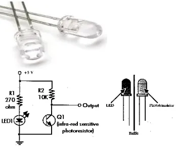
4.IR sensors:
Available online: https://edupediapublications.org/journals/index.php/IJR/ P a g e | 905
module, take out 3 wires of sufficiently long length (say 1 ft). Then, as shown above, connect them to VCC, preset and to ground on main board. By adjusting preset, you can adjust sensitivity of the sensor. VCC should be connected to 5V supply. IR TRANSMITTER
Fig-5.5: IR LED
IR LED emits infrared radiation. This radiation illuminates the surface in front of LED. Surface reflects the infrared light. Depending on the reflectivity of the surface, amount of light reflected varies. This reflected light is made incident on reverse biased IR sensor.
Fig-5.6:IR RECEIVER
5.Motor: Motor is a device that creates motion, not an engine; it usually refers to either an electrical motor or an internal combustion engine
Fig 5.7:Motor
6.
Power supplyFig-5.8: power supply
TRANSFORMER
Transformers are used to convert electricity from one voltage to another with minimal loss of power. They only
work with AC (alternating current) because they require a changing magnetic field to be created in their core. Transformers can increase voltage (step-up) as well as reduce voltage (step-down).
RECTIFIER
The purpose of a rectifier is to convert an AC waveform into a DC waveform (OR) Rectifier converts AC current or voltages into DC current or voltage. There are two different rectification circuits, known as 'half-wave' and 'full-wave' rectifiers. Both use components called diodes to convert AC into DC.
FILTER
A filter circuit is a device which removes the ac component of rectifier output but allows the dc component to the load. The most commonly used filter circuits are capacitor filter, choke input filter and capacitor input filter or pi-filter. We used capacitor filter here.
7. Vibration sensor:
Critical to vibration monitoring and analysis is the machine mounted sensor. Three parameters representing motion detected by vibration monitors are displacement, velocity, and acceleration. These parameters are mathematically related and can be derived from a variety of motion sensors. Selection of a sensor proportional to displacement, velocity or acceleration depends on the frequencies of interest and the signal levels involved. Figure 1 shows the relationship between velocity and displacement to constant acceleration. Sensor selection and installation is often the determining factor in accurate diagnoses of machinery condition.
8.LCD Display:
A liquid crystal display (LCD) is a thin, flat display device made up of any number of color or monochrome pixels arrayed in front of a light source or reflector. Each pixel consists of a column of liquid crystal molecules suspended between two transparent electrodes, and two polarizing filters, the axes of polarity of which are perpendicular to each other. Without the liquid crystals between them, light passing through one would be blocked by the other. The liquid crystal twists the polarization of light entering one filter to allow it to pass through the other.
A program must interact with the outside world using input and output devices that communicate directly with a human being. One of the most common devices attached to an controller is an LCD display. Some of the most common LCDs connected to the contollers are 16X1, 16x2 and 20x2 displays.This means 16 characters per line by 1 line 16 characters per line by 2 lines and 20 characters per line by 2 lines,respectively.
Many microcontroller devices use 'smart LCD' displays to output visual information.
Shapes and S
Available online: https://edupediapublications.org/journals/index.php/IJR/ P a g e | 906
Fig-5.9: pin diagram of 1x16 lines LCD
6. BLOCK DIAGRAM
Fig-6.1:Block diagram
7.
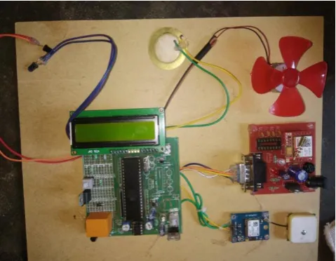
HARDWARE DESCRIPTION
Fig 7.1: Hardware connection
GPS receiver works on 9600 baud rate is used to receive the data from space Segment (from Satellites), the GPS values of different Satellites are sent to microcontroller AT89S52, where these are processed and forwarded to GSM. At the time of processing GPS receives only $GPRMC values only. From these values microcontroller takes only latitude and longitude values excluding time, altitude, name of the satellite, authentication etc. E.g. LAT: 1728:2470 LOG: 7843.3089 GSM modem with a baud rate
57600.GSM is a Global system for mobile communication in this project it acts as a SMS Receiver and SMS sender. EEPROM is an Electrically Erasable read only memory which stores is used to store the mobile number. The power is supplied to components like GSM, GPS and Micro control circuitry using a 12V/3.2A battery .GSM requires 12v,GPS and microcontroller requires 5v .with the help of regulators we regulate the power between three components.
To register a number into microcontroller send a random letter to the gsm number. Then the number will be registered .To change the number reset button was provided .In order to trace the system, the user has to send *1 as a message to the system and the system will reply the GPS location. The GPS location is sent to the requested user as:
Latitude:1234.123456N
Longitude:12.123456E
When an accident was occurred then the vibration sensor will responds and send signal to microprocessor the immediately the gsm module sends the
message as “accident occurred@ Latitude:1234.123456N Longitude:12.123456E” to the numbers which were registered in the source code and the gsm initialization registered number.
When someone was trying to access your vehicle then there was an ir sensor provided.if any one have opened the door of your vehicle then the ire sensor senses the signal and send the signal to microcontroller.then the gsm will sends “someone was accessed your vehicle@ Latitude:1234.123456N Longitude:12.123456E”
The bracks will be applied from your location by sending an sms to gsm module as “*B”. Then the gsm receives the sms and the microprocessor will sends signal to stop the vehicle as here the motor will be stopped.then the gsm will sends an acknowledgment to user as “ bracks applied@ Latitude:1234.123456N Longitude:12.123456E”.
8. ADVANTAGES
1. The cost of implementation of the project was low 2. Better security will be provided for the vehicle 3. Tracking of the vehicle can be done easily
4. Remote communication using GSM modem from anywhere in world.
Available online: https://edupediapublications.org/journals/index.php/IJR/ P a g e | 907
6. Sends location in the form of latitude and longitude. 7. Automatic accident location alert to police/ambulance. 8. Theft control through GSM short message service. 9. The system is simple to design and easy to use. 10. The system is reliable and consumes less power. 11. Installation of the system is very easy.
12. We get the exact co-ordinates of location. So there is no chance of errors.
9.
APPLICATIONS
1. GPS Car theft detection can be used in transportation vehicles of Companies, schools, colleges and industries. 2. This project can be used in our cars and even in bikes. 3. VIP vehicle tracking
4. Can also be used for Child or animal tracking 5. Vehicle Security Applications
6. Ambulance tracking 7. Navigation systems .
10. RESULTS
Fig10.1: Number Registration
Fig-10.2: Accident Detection
Fig-10.3: Brackes Applied and
security protection of vehicle
Fig-10.4: Vehicle Tracking
11.CONCLUSION AND FUTURE SCOPE
CONCLUSION:
Thus this project had done the security, safety and navigation operations in a vehicle.This provides the security to vehicle was provided by using IR sensors while anyone tries to access your vehicle. The vehicle tracking can be done at any anytime from any location. Accident occurred in a vehicle was detected and notification was send to the registered numbers as example: hospital, police and home number and the vehicle is controlled from remote location.
FUTURE SCOPE:
The project can be implemented with internet facility and More security can be provided further The project will be extended to work in remote locations when there were no signals to the GSM module
REFERENCES
1. M.S. Joshi, Deepali V. Mahajan, “Arm 7 Based Theft Control, Accident Detection &Vehicle Positioning System,” International
Available online: https://edupediapublications.org/journals/index.php/IJR/ P a g e | 908
2. Mr.S.Iyyappan,Mr.V.Nandagopal, “Automatic Accident Detection and Ambulance Rescue with Intelligent Traffic Light System,”
International Journal of Advanced Research in Electrical, Electronics and Instrumentation Engineering Vol. 2, Issue 4, April 2014.
3.Montaser N. Ramadan, Mohammad A. Al-Khedher, Senior Member, IACSIT, and Sharaf A. Al-Kheder, “Intelligent Anti-Theft and Tracking System for Automobiles,” International Journal of
Machine Learning and Computing, Vol. 2, No. 1, February 2013.
4. Nirav Thakor, Tanmay Vyas, Divyang Shah, “Automatic Vehicle Accident Detection System Based on ARM &GPS,” International Journal for Research in Technological Studies, ISSN: - Applied (Online) Vol-1, Issue - 1, Dec 2012.
5.Varsha Goud, V.Padmaja, “Vehicle Accident Automatic Detection and Remote Alarm Device,” International Journal of Reconfigurable and Embedded Systems (IJRES). Vol. 1, No. 2, July 2012, pp. 49~54 ISSN: 2089-4864.
6. Kevin King, S.W. Yoon, N.C. Perkins, K. Ajani, “Wireless MEMS inertial sensor system for golf swing dynamics”, Sensors and Actuators A:
Physical, vol.141,pg 2, 2008.
7. Jorge Salivary, Carlos T. Caliphate, Juan Carlos Cano,Pietro Manzoni” Providing Accident Detection in VehicularNetworks Through OBD-II
Devices and Android-based Smartphones” in 5th IEEE Workshop On User MObility and Vehicular Networks 2011 pp no : 978-1- 61284 928- 7
8. Md. Syedul Amin, Jubayer Jalil, M. B. I. Reaz “AccidentDetection and Reporting System using GPS, GPRS and GSM Technology” in
IEEE/OSA/IAPR International Conference on Informatics, Electronics & Vision in 2012 pp no : 978-1- 4673-1154- 0/12.
9. R. Rathinakumar and D. Manivannan “Wireless AccidentInformation System Using GSM and GPS” in ResearchJournal of Applied Sciences,
Engineering and Technology 4(18): 3323-3326, 2012, ISSN: 2040-7467.
10. C.Vidya Lakshmi, J.R.Balakrishnan “Automatic Accident Detection via Embedded GSM message interface withSensor Technology” in
International Journal of Scientific and Research Publications,Volume2,Issue1.
11. N.Watthanawisuth,T.LomasandA.Tuantranont, ―Wireless Black Box Using MEMS Accelerometer and GPS Tracking for Accidental Monitoring
of Vehicles‖, Proceedings of the IEEE-EMBS International Conference on Biomedical and Health Informatics (BHI 2012) Hong Kong and
Shenzhen, China, 2-7 Jan 2012.
12. Chulhwa Hong, Truong Le, Kangsuk Chae, and Souhwan Jung. ―Evidence Collection from Car Black Boxes using Smartphone's‖. 2011
IEEE, Annual IEEE Consumer Communications and Networking Conference, vol. 16, issue5.pp.647- 656,August 2007.
BIOGRAPHIES
SaiKrishna. Meda was born inAndhra Pradesh,India. He is pursuing B. Tech degree in Electronics and Communication Engineering at Lakireddy Balireddy College of Engineering, Mylavaram, Andhra Pradesh, India From 2014-2018.His research interests covers Communication Devices ,Embedded systems and Digital Electronics.
Mohansesha Reddy. Karri was born in Andhra Pradesh, India. He is pursuing B. Tech degree in Electronics and Communication Engineering at Lakireddy Balireddy College of Engineering, Mylavaram, and Andhra Pradesh, India From 2014-2018.His research interests covers Communication Devices , Embedded systems and Digital Electronics..
Available online: https://edupediapublications.org/journals/index.php/IJR/ P a g e | 909 Suresh Babu. Ala was born inAndhra Pradesh,India.