VHF-LB VEST ANTENNA
A. Jafargholi and A. Hosseinbeig
Department of Electrical Engineering K. N. Toosi University of Technology Tehran, Iran
M. Emadi, L. Farhoudi, and S. A. Golgun
Antenna and EMC/EMI Laboratory
Shahid Beheshti Institute of Communication Tehran, Iran
Abstract—In this paper, a new simple VHF-LB vest antenna is proposed, simulated, fabricated and tested. The simulation results for various user’s positions such as standing, kneeling and prone on the ground are obtained and compared with conventional whip antenna mounted on mobile unit. It is shown that the proposed antenna outperforms the whip antenna in terms of gain and body energy absorption. The measurements results of proposed vest antenna confirm the simulation results.
1. INTRODUCTION
It is critical for coordination and control of mobile personnel to maintain communications on some occasions. Usually protruding antennas like whip antenna have two main drawbacks, first the personnel carrying the equipment can be an easily detectable target; second it limits the movement due to rough field environments especially in military applications. These limitations can be eliminated by replacing whip antenna with flexible fabric antennas. These types of antennas are lightweight and conformal with body shape, and unlike conventional whip antenna, which is rugged and massive in nature, may be easily integrated with clothing in the form of strip vest or jacket. There are three main types of wire antennas suggested for wearable
applications: The folded loop [1, 2], Minkovski fractal [3] and Meander-Line Bowtie antennas [4]. Another type of wearable antenna uses various kinds of low profile microstrip antennas commercially used in mobile handsets [5, 6]. It should be noted that these types of antennas are usually used for narrowband applications; therefore some wideband textile antennas were introduced in the past [7–9]. Another type of wearable antenna that can work over 3 MHz to 3 GHz is presented in [10–12].
In [13], the self-structuring antennas (SSA) were proposed and as stated in this paper, the SSA is a number of wires or patches interconnected with controllable switches. SSA can adapt itself to give optimal performance where the antenna environment changes. In [14], the radiation gain matching performance of this antenna, specific absorption rate (SAR) and the antenna effects on human body were investigated. It can be seen in this antenna the complexity of wire selection and switching is very high.
In this paper, a new type of wideband vest antenna matched for the entire 30–80 MHz is illustrated. The proposed antenna is highly flexible and lightweight causing the least amount of discomfort to user. In contrast to previous versions, it is made very easy with minimum complexity. The antenna prototype is built, simulated and tested for various cases, and the results are presented. In order to verify that the antenna is not hazardous for human body we investigated the effects of antenna radiation on a human body Our studies concentrate on the evaluation of SAR [15–22]. Although the interaction between electromagnetic fields (EMF) and a human body has been of interest to the scientific community [23, 24], the main concern was the effects of antennas on human head for cellular phone frequencies [25–29]. Thus to specify the acceptable levels of EMF absorption on human body some regulated standards were reviewed [30–32] and compared with simulations and measurements.
2. VEST ANTENNA DESIGN AND SIMULATION
The structure is very lightweight and provides good air circulation which is a rigid double-loop transformed into a wearable flexible antenna. Copper tape is used to reinforce the connections and to allow soldering of the feed transmission line (Fig. 1(a)). The thin non-conducting cloth is applied to provide mechanical strength and to prevent tearing.
(a) (b)
(c)
Feed Point
a b
c d
Feed Point
Figure 1. Designed vest antennas. (a) Strip vest, (b) antenna parameters, and (c) feed network.
back. The coaxial shield is attached to a small copper tape at the back of the vest, while the center conductor is attached to the one of the loops, (Fig. 1(c)).
The lowest point of the vest is 1 m above the ground. The width of the vest is approximately 40 cm while the depth is 20 cm and the height is approximately 70 cm. In Fig. 1(b), 1 represents the left loop while 2 is the right loop acting as parasitic element. The matching network and antenna feed point is labeled 3. In Fig. 1(b), a= 7 cm,
b= 21 cm,c= 4 cm,d= 1 cm and all the other parts are same as these samples.
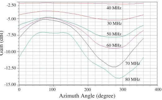
The antenna was analyzed by HFSS and CST in VHF-LB frequencies to evaluate the antenna gain and average SAR on human body. The antenna gain for azimuth angles versus VHF-LB frequencies are plotted in Fig. 2.
30 MHz 40 MHz
50 MHz 60 MHz
70 MHz
80 MHz
0 100 200 300 400 -2.50
-7.50
-10.00
-15.00 -12.50 -5.00
Gain (dBi)
Azimuth Angle (degree)
Figure 2. Gain of designed strip vest antenna v.s. azimuth angle.
caused due to the effect of legs and hands on radiation pattern. However, because of human legs, as frequency increases to 70 MHz (human body resonance frequency) this effect becomes significant. The maximum gain of antenna is about −2.5 to −7.5 dBi over the entire frequency bandwidth which is 5 to 9 dB lower than standard whip antenna (maximum gain is about−2.5 at lower frequencies to 2.5 dBi at the end of the band).
In contrast to the general principle stating that the maximum gain of a conventional antenna increases due to frequency increase, in vest antenna maximum gain decreases because of the increase of human body absorption at VHF frequencies being maximum at 70–80 MHz (resonance frequency). Although in lower frequencies the gain increase is observed, gain decrease appears in higher frequencies. In Fig. 2, the increase of absorption at higher frequencies, near the human resonance frequency can be seen clearly.
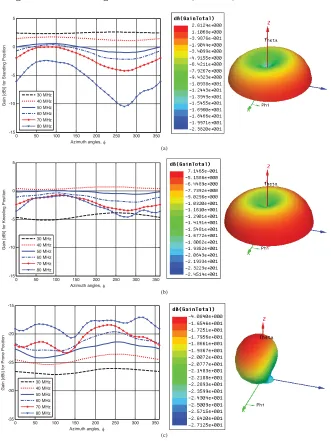
Preliminary evaluation performance of the vest antenna has been tested and proven to be efficient. Therefore, to manufacture the vest antenna some different positions of body including standing, kneeling and prone were simulated.
0 50 100 150 200 250 300 350 -15 -10 -5 0 5
Azimuth angles, φ
G a in [d Bi ] fo r Sta n d in g Po s iti o n 30 MHz 40 MHz 50 MHz 60 MHz 70 MHz 80 MHz (a)
0 50 100 150 200 250 300 350
-15 -10 -5 0 5
Azimuth angles, φ
G a in [d Bi ] fo r K n e e lin g Po s iti o n 30 MHz 40 MHz 50 MHz 60 MHz 70 MHz 80 MHz (b)
0 50 100 150 200 250 300 350
-35 -30 -25 -20 -15
Azimuth angles, φ
G a in [d Bi ] f o r Pr o n e Po s iti o n 30 MHz 40 MHz 50 MHz 60 MHz 70 MHz 80 MHz (c)
model is located in z direction while the ground plane is x-y plane. The model faces toward y-axis while in prone position it lays along y direction.
Moreover, the safety assessment including the simulation of specific absorbency rates is essentially done and is compared to related safety standards. In next section human body model and the antenna radiation effects on human body is presented by means of SAR investigation.
3. HUMAN BODY MODEL AND SAR COMPARISON FOR WHIP AND VEST ANTENNAS
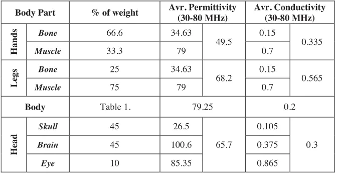
In our studies we use a four-part model of the human body, consisting of head, body, hands and legs. As the tissues have approximately the same mass density [20], the permittivity and conductivity are represented based on different weight and volume of each organ [33], as shown in Tables 1 and 2.
Table 1. Human body EM properties, [33] and [34].
Organ ε
400 MHz 400 MHz Size Mass[kg]
% of human weight Heart 66 0.97 12×8-9×6 cm3 0.25-0.35 0.5
Kidney 66.4 1.1 12×5×6 cm3
0.15 0.5
Liver 51.2 0.65 20-22.5×15-17.
5×10-12.5 cm3 1.3-3 3.3
Lung 54.6 0.68 25×30×5 cm3 0.625 (R),
0.567 (L) 1.8
Stomach 67.5 1.00 50 mlit – 1 lit 0.48-0.52 0.8
Muscle 58.8 0.84 - 6-7 10
Intestine 66.1 1.9 - 1.8-2.4 3
Bone 13.1 0.09 - 5-7 8.3
Blood 64.2 1.35 - - 5
Water 81 0.001 - - 66.8
σ
r [S/m]
The electromagnetic parameters (permittivity and conductivity) of some human organs at 400 MHz and VHF-LB are obtained from [20] and [34] respectively, where the commercial CST microwave studio uses the presented information in [34] as human body model.
Table 2. Human body model.
Body Part % of weight Avr. Permittivity
(30-80 MHz)
Avr. Conductivity (30-80 MHz)
Hands
Bone 66.6 34.63
49.5
0.15
0.335
Muscle 33.3 79 0.7
Leg
s Bone 25 34.63
68.2
0.15
0.565
Muscle 75 79 0.7
Body Table 1. 79.25 0.2
Head
Skull 45 26.5
65.7
0.105
0.3
Brain 45 100.6 0.375
Eye 10 85.35 0.865
size. All results were obtained from extensive full-wave electromagnetic simulations using commercial solver Ansoft HFSS and CST microwave studio.
In Table 1, the size, mass and the percentage of human weight for some organs are presented, while the permittivity and conductivity of these organs are specified for 400 MHz [20].
By computing the average permittivity and conductivity,gi, which are defined as
gi =
i
g(f)·Wi where g=εr, σ (1)
Where, i and W represent the included organs and weight of each one per each part of human body, respectively; permittivity and conductivity are extracted using the percentage information and a simple averaging for each part of the illustrated model. The results are presented in Table 2.
It is assumed that the human head is consisted of skull, brain and eyes. Hands and legs are composed of muscles and bones and the rest of the body is assumed to be muscles, bones, heart, intestine, liver, kidney, lungs, stomach, blood and water.
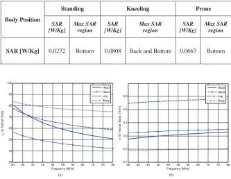
Table 3. Maximum SAR V.S. body position.
Body Position
Standing Kneeling Prone
SAR [W/Kg] Max SAR region SAR [W/Kg] Max SAR region SAR [W/Kg] Max SAR region
SAR [W/Kg] 0.0272 Bottom 0.0808 Back and Bottom 0.0667 Bottom
30 35 40 45 50 55 60 65 70 75 80 30 40 50 60 70 80 90 100 Frequency [MHz] εr f o r H u m a n B ody Head Hand Leg Body
30 35 40 45 50 55 60 65 70 75 80 0.1 0.2 0.3 0.4 0.5 0.6 Frequency [MHz] σ fo r H u m a n Bo d y , [S/m ] Head Hand Leg Body
(a) (b)
Figure 4. Presented human body model, contains a four part model, v.s. frequency (a) permitivity, and (b) conductivity.
The SAR simulation results for standing, kneeling and prone positions are extracted in Table 3. Fig. 6 shows that in vest antenna the maximum SAR is located at the bottom of the body and it is far from the head. It is shown in Table 3 that the maximum SAR occurred in kneeling position which is about 0.08 [W/kg], approximately 3 times greater than standing and 1.2 times greater than prone positions. According to ANSI/IEEE standard the maximum of average SAR’s in one gram of tissue in the shape of a cube should not exceed 1.6 W/kg and the average SAR of the whole body mass should not exceed 0.08 W/kg. ICNIRP’s guidelines indicate that an average SAR in the head over a 10 g tissue cube should not exceed 2 W/kg.
Figure 5. Vest (left) and whip (right) antenna simulation.
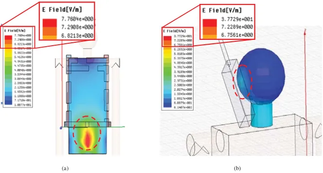
(a) (b)
Figure 6. SAR simulation results for vest (a) and whip (b) antenna.
Table 4. The comparison between designed vest antennas.
Parameters Strip Vest
Antenna
Whip Antenna
-6 to -4 dBi -1 to 5 dBi
Emag 7.76 V/m 37.7 V/m
Maximum
Average SAR 0.027 W/kg 0.378 W/kg
Maximum SAR
location Bottom Head
Antenna Gain v.s. Minimum of Maxmum and
Frequency
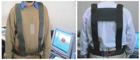
4. MEASUREMENTS RESULTS
The prototype vest antenna is shown in Fig. 7. The radiation patterns of the antenna were measured, Fig. 8. A conventional whip antenna was used as reference antenna while a short helical antenna (15 cm), another whip antenna and the implemented vest antenna are tested as both receiver and transmitter antennas. The vest antenna was tested successfully in some different positions, including standing, kneeling, and prone, while the measurements results for kneeling and prone position over 40–50 MHz which is specified with dashed lines are included in Fig. 8(a).
To compare the antenna gain, all of these three types of antennas were tested as transmitter antenna, while the maximum power level sent by the transmitter is about 400 mW and they were tested in 1 km far from the receiver.
The received signal levels are shown in Fig. 8(a). Likewise to simulation results, the gain of the vest antenna is about 5 to 10 dB lower than the standard whip antenna which confirms the aforementioned simulation results. Moreover, measurements show that the pattern of the illustrated vest antenna is approximately omnidirectional, especially in low frequencies that verified the simulation results, Fig. 8(b).
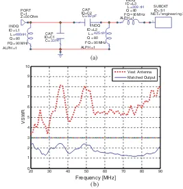
All of aforementioned measurements have been done using a matching network which is described below. A matching network was designed for entire VHF-LB using ADS and MW-Office software as shown in Fig. 9(a). The designed matching network is simple and contains three inductances and two capacitances. While worn, it is essential to minimize the sensitivity of antenna impedance to the human movements and environment changes, therefore the test of the designed antenna with its matching network for various positions is important. Moreover the sensitivity analysis of the matching network to each element of the designed circuit must be checked. In this case, using ADS software, simulations showed that the sensitivity of matching to the tolerance of elements is negligible, which we do not present the results here. In Fig. 9(b), the VSWR response of matched vest antenna is compared with un-matched vest antenna.
To check the antenna safety, SAR and the near H field in simulations, regulated standards and the measured values must be compared. In Table 5, measurement of near H field and simulation results for both whip and vest antenna are summarized. As shown in this table, whip antenna’s near H field is higher and therefore, its effects on human body as larger than vest antenna, while both whip and vest have acceptable levels with regard to the limitations of standards, except the position of whip near human’s head or in front of antenna feed which reaches standard limits.
As it is seen in this table, the measurement results confirm simulation results thus; the proposed human body model is accurate enough for this problem. Furthermore, in whip antenna, the maximum SAR occurres in the human’s head while in illustrated vest antenna it occurres in the feet. In Table 5, the critical points are specified by highlighted cell.
30 35 40 45 50 55 60 65 70 75 80 -80
-75 -70 -65 -60 -55 -50 -45 -40 -35
Frequency (MHz)
R
e
c
e
iv
e
d
le
v
e
l
(d
B
m
)
Vest-Standing Whip Helical Vest-Kneeling Vest-Prone
(a)
0 50 100 150 200 250
-70 -65 -60 -55 -50 -45
Azimuth angles, φ
R
e
c
e
iv
ed l
e
v
e
l
(d
B
m
)
30 MHz 40 MHz 50 MHz 70 MHz
(b)
Figure 8. Antenna measurement test level, for vest, short helical and whip antennas over 30–80 MHz.
ALPH FQ Q L ID 1 90 MHz 80 480nH L1 CAP C= ID=C2 82 pF 1 SUBCKT NET= ID=
"engineeri ng 3" S1 PORT
Z=50 Ohm P=1
(a)
20 30 40 50 60 70 80 90
0 1 2 3 4 5 6 7 8 9 10 VSWR Vest Antenna Matched Output (b) Frequency [MHz] = = = = = INDQ 425 nH L2 ALPH FQ Q L ID 1 90 MHz 80 = = = = = INDQ 309 nH L3 ALPH FQ Q L ID 1 90 MHz 80 = = = = = INDQ CAP C= ID=C1 33 pF
Figure 9. Matching network. (a) Matching circuit, (b) input measured VSWR, before and after matching.
Table 5. Near field H, simulation and measurement results for vest and whip antenna.
Standard value Simulation (A/m) Measurement Results H (A/m) Measurement Points Vest Whip Vest Whip 0.16 0.09 0.49 0.0794 0.4962 Head (right) 0.16 0.09 0.066 0.070 0.085 Head (left) 0.16 0.016 0.054 0.0103 0.0658 Head (front) 0.16 0.012 0.064 0.0095 0.1000 Head (back) 0.16 0.011 0.028 0.0090 0.0265 Near the Heart
0.16 0.028
0.028 0.0241 0.025 Front of Body
0.16 0.028
0.028 0.020 Back of Body
5. CONCLUSION
In this paper, a new simple VHF-LB vest antenna is proposed, simulated, fabricated and tested. The simulation results for various user’s positions, such as standing, kneeling and prone on the ground are obtained and compared with conventional whip antenna mounted on mobile unit. It is shown that the proposed antenna outperforms the whip antenna in terms of Gain and body energy absorption. The measurements results of proposed vest antenna confirm the simulation results.
REFERENCES
1. Hayashida, S., H. Morishita, Y. Koyanagi, and K. Fujimoto, “Wideband folded loop antenna for hadsets,”IEEE Antennas and Propagation Int. Symp., 2–5, 2002.
2. Hayashida, S., T. Tanaka, H. Morishita, Y. Koyanagi, and K. Fujimoto, “Built-in half size folded dipole antenna for hadsets,”
IEEE Antennas and Propagation Int. Symp., 2759–2762, 2004. 3. Gianvittorio, J. P. and Y. Rahmat-Samii, “Fractal antennas: A
novel antenna miniaturization technique,” IEEE Antennas and Propagation Magazine, Vol. 44, 20–36, 2002.
4. Ali, M. and S. Stuchly, “A meander-line bow-tie antenna,” IEEE Antennas and Propagation Int. Symp., 1566–1569, 1996.
5. Tronquo, A., H. Rogier, C. Hertleer, and L. Van Langenhove, “Robust planar textile antenna for wireless body LANs operating in 2.45 GHz ISM band,” Electronics Letters, Vol. 42, No. 3, Feb. 2006.
6. Klemm, M., I. Z. Kov´cs, G. F. Pedersen, and G. Tr¨oster, “Novel small-size directional antenna for UWB WBAN/WPAN applications,”IEEE Trans. on Antennas and Propagation, Vol. 53, No. 12, 3884–3896, Dec. 2005.
7. Merenda, J. T., Digital Wideband Small Antenna Systems, BAE Systems, Jul. 2006.
8. Merenda, J. T., Crossed-loop Radiation Synthesizer System, US Patent, 6680710, Jan. 2004.
9. Merenda, J. T., Radiation Synthesizer Feed Configuration, US Patent, 6606063, Aug. 2003.
10. Adams, R. C., Wearable Directional Antenna, US Patent, 6995723, Feb. 2006.
12. Adams, R. C., R. J. O’Neil, J. E. Lebaric, and T. R. Emo,
Integrated Man-prortable Wearable Antenna System, US Patent, 7002526, Feb. 2006.
13. Coleman, C. M., E. J. Rothwell, J. E. Ross, and L. L. Nagy, “Self-structuring antennas,” IEEE Antennas and Propagation Magazine, Vol. 44, 11–23, 2002.
14. Fenner, R. A., “Bandwidth extension of a body worn antenna vest,” M.S. Thesis, Michigan State University, 2007.
15. Klemm, M. and G. Troester, “EM energy absorption in the human body tissues due to UWB antennas,”Progress In Electromagnetics Research, PIER 62, 261–280, 2006.
16. Chen, Z. N.,Antennas for Portable Devices, John Wiley & Sons Ltd, 2007.
17. Hirata, A., K. Shirai, and O. Fujiwara, ”On averaging mass of SAR correlating with temperature elevation due to a dipole antenna,” Progress In Electromagnetics Research, PIER 84, 221– 237, 2008.
18. Kouveliotis, N. K. and C. N. Capsalis, ”Prediction of the SAR level induced in a dielectric sphere by a thin wire dipole antenna,”
Progress In Electromagnetics Research, PIER 80, 321–336, 2008. 19. Liu, Y., Z. Liang, and Z. Q. Yang, “Computation of
electromagnetic dosimetry for human body using parallel FDTD algorithm combined with interpolation technique,” Progress In Electromagnetics Research, PIER 82, 95–107, 2008.
20. Kim, J. and Y. Rahmat-Samii, “Implanted antennas inside a human body: Simulations, designs, and characterizations,” IEEE
Trans. on Microwave Theory and Techniques, Vol. 52, No. 8,
Aug. 2004.
21. Yoshida, K., A. Hirata, Z. Kawasaki, and T. Shiozawa, “Human head modeling for handset antenna design at 5 GHz band,”
Journal of Electromagnetic Waves and Applications, Vol. 19,
No. 3, 401–411, 2005.
22. Pino, A. G., M. Arias, M. G. Sanchez, I. Cuinas, and A. A. Alonso, “Determination of safety volumes for medium-frequency emissions under standard limits of human exposure,”
Journal of Electromagnetic Waves and Applications, Vol. 17,
No. 11, 1605–1611, 2003.
23. Rosen, A., M. A. Stuchly, and A. Vander Vorst, “Applications of RF/microwaves in medicine,” IEEE Trans. on Microwave Theory and Techniques, Vol. 50, No. 3, 963–974, Mar. 2002.
the heads of adults and children,”Bioelectromagnetics, Sep. 2005. 25. Ebrahimi-Ganjeh, M. A. and A. R. Attari, “Interaction of dual band helical and PIFA handset antennas with human head and hand,”Progress In Electromagnetics Research, PIER 77, 225–242, 2007.
26. Kuo, L. C., Y. C. Kan, and H. R. Chuang, “Analysis of a 900/1800-MHz dual-band gap loop antenna on a handset with proximate head and hand model,” Journal of Electromagnetic Waves and Applications, Vol. 21, No. 1, 107–122, 2007.
27. Kouveliotis, N. K., P. J. Papakanellos, E. D. Nanou, N. I. Sakka, V. S. G. Tsiafkis, and C. N. Capsalis, “Correlation between SAR, SWR and distance of mobile terminal antenna in front of a human phantom: Theoretical and experimental validation,” Journal of Electromagnetic Waves and Applications, Vol. 17, No. 11, 1561– 1581, 2003.
28. Keshvari, J. and S. Lang, “Comparison of radio frequency energy absorption in ear and eye region of children and adults at 900, 1800 and 2450 MHz,” Physics in Medicine and Biology., Vol. 50, 4355–4369, 2005.
29. Kouveliotis, N. K., S. C. Panagiotou, P. K. Varlamos, and C. N. Capsalis, “Theoretical approach of the interaction between a human head model and a mobile handset helical antenna using numerical methods,”Progress In Electromagnetics Research, PIER 65, 309–327, 2006.
30. ICNIRP, “Guidelines for limiting exposure to time-varying electric, magnetic and electromagnetic fields (up to 300 GHz),”
Health Phys., Vol. 74, 494–522, 1998.
31. ANSI C95.1-1982, “American national standard safety levels with respect to human exposure to radiofrequency electromagnetic fields, 300 kHz to 100 GHz,” The Institute of Electrical and Electronics Engineers, Inc., 345 East 47th Street, NY 10017, New York.
32. European Prestandard ENV 50166-2, “Human exposure to electromagnetic fields: High frequencies (10 kHz to 300 GHz),” CENELEC, CENELEC Central Secretariat: Rue de Stassart 35 B-1050, Brussels, Belgium, Jan. 1995.
33. http://www.britannica.com/