Reading Distance Estimation for Vehicle RKE Systems
Han-Joong Kim1, Hosung Choo2, and Gangil Byun3, *
Abstract—In this paper, we propose a systematic simulation-based approach to estimate the reading distance of an RKE system. In our electromagnetic (EM) simulation, a receiving RKE antenna and a vehicle structure, including both exterior and interior, are modeled as piece-wise mesh triangles to obtain accurate radiation characteristics of the antenna mounted inside the vehicle. The reading distance is then estimated by a two-ray propagation model that includes effects of space loss, ground properties, and antenna polarizations for various orientations and heights of handheld devices. The estimated distances are compared to the measurement, and results show that the proposed approach is suitable to replace the measurement-based approach with an average error of less than 2 m.
1. INTRODUCTION
The remote keyless entry (RKE) system has become one of the most essential on-board systems in vehicles to perform functions for door locks and klaxons [1–3]. This remote system is made possible by the use of radio waves between a handheld device and a control unit located inside the vehicle [4, 5]. The control unit contains an RKE antenna that receives a coded signal transmitted from the handheld device; thus, the reading distance of the system is determined by radiation characteristics of the RKE antenna. To improve radiation characteristics, a lot of effort has been focused on developing a standalone RKE antenna with a higher gain and an omni-directional pattern [6–10]. Despite the antenna performance improvement, the reading range cannot be ensured for all directions of remote access because the most critical factor reducing the range is caused by wave blockage, reflection, and coupling effects from the vehicle structure. To minimize these effects, the RKE system has been tuned by measuring the reading distance for all directions, which can only be obtained after the mass production process of the prototype vehicles. However, this is a time-consuming process that requires a large amount of manpower because the measurement should be applied to all line-up models through repeated revision processes [11]. Thus, there has been a growing demand for an efficient and systematic approach to replace this measurement-based method taking a lot of resources.
In this paper, we propose a systematic simulation-based approach to estimate the reading distance of an RKE system as a replacement for the measurement-based method. Our approach begins with a modeling process for EM simulation. To obtain the radiation characteristics of the RKE antenna installed inside a vehicle structure, the antenna is modeled as conducting wire-segments, and both the interior and exterior structures of the vehicle are included as conducting piece-wise triangles in our EM simulation using the FEKO EM simulator [12–14]. The reading distance is then estimated using a two-ray propagation model to take into account environmental effects, such as ground properties, antenna polarizations, orientations and heights of handheld devices. The suitability of the proposed approach is demonstrated by comparing the estimated reading distance to the open-site measurement, and the result shows that the proposed approach is suitable for use as a replacement for the current measurement-based method.
Received 27 June 2016, Accepted 22 November 2016, Scheduled 5 December 2016
* Corresponding author: Gangil Byun ([email protected]).
2. PROPOSED ESTIMATION PROCEDURE
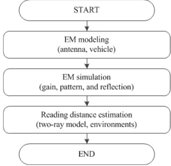
Figure 1 shows a flowchart of the proposed simulation-based approach to estimate the reading distance of RKE systems, which begins with the EM modeling process of a standalone RKE antenna and a vehicle structure. The RKE antenna used in our approach has an operating frequency of 433 MHz and is modeled as conducting wire-segments fed by a coaxial probe. Since the antenna is placed inside the vehicle, the interior structures, such as body frames, steering wheels, seats, and control boxes, are included along with the exterior as piece-wise mesh triangles. Then, the radiation characteristics of the antenna are measured in a semi-anechoic chamber to revise the modeling process in comparison with the simulation. After revising the process, the reading distance of the RKE system is estimated using a two-ray propagation model that is useful for considering additional environmental effects (e.g., ground properties, antenna polarizations, orientations and heights of handheld devices) that are critical to the system performance.
Figure 1. Flow chart of the estimation method for vehicular RKE antennas.
(b) (a)
Figure 2. EM modeling structure. (a) Design parameters of the RKE antenna. (b) Cross-section view of the rubber cover.
Table 1. Parameters of the RKE antenna.
Parameters Value
h1 (mm) 66
d1 (mm) 6 Number of turns (turns) 13.5
h2 (mm) 5.5
d2 (mm) 6
h3 (mm) 2
d3 (mm) 8.1
h4 (mm) 4
d4 (mm) 3
h5 (mm) 5 Wire radius (mm) 0.1
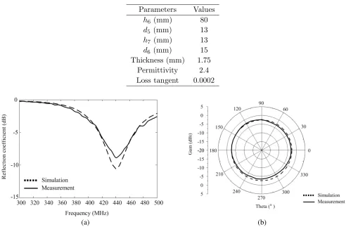
Table 2. Parameters of the rubber cover.
Parameters Values
h6 (mm) 80
d5 (mm) 13
h7 (mm) 13
d6 (mm) 15 Thickness (mm) 1.75
Permittivity 2.4 Loss tangent 0.0002
(a) (b)
Figure 3. Simulated and measured results. (a) Reflection coefficient. (b) Azimuth radiation pattern at 440 MHz.
Figure 4. Geometry of a commercial vehicle.
(a) (b)
Figure 5. Geometry of the antenna mounted on the frame. (a) Side view. (b) Top view.
antenna exhibits an average azimuth gain of−3.10 dBi with an omni-directional property (gain deviation ≤1.77 dB).
Figure 4 shows the geometry of a commercial vehicle (1.68 m×4.69 m×1.88 m) that is used to estimate the reading distance of the RKE system. Some interior structures, such as steering wheels, vehicle audio systems, gear shifts, and body frames, are included and modeled as piece-wise mesh triangles in our EM simulation; however, some dielectric structures (e.g., plastic covers, leather seats, tires, and windows) are removed to minimize the computational load for reduced simulation time [15]. The RKE antenna is then mounted on the left side of a vertical frame located underneath the center fascia, and a ground extender is used to attach the antenna to the vertical frame for installation. Figs. 5(a) and (b) show side and top views of the antenna with the extender, whose dimensions are
l1 = 28 mm,l2 = 25 mm,l3 = 22 mm, andw1 = 22 mm.
Figure 6 shows the measured and simulated reflection coefficients of the antenna installed on the vehicle. The measured resonant frequency is slightly shifted toward the lower frequency band (from 440 MHz to 430 MHz), compared to the results presented in Fig. 3(a), due to the effect of the vehicle structure.
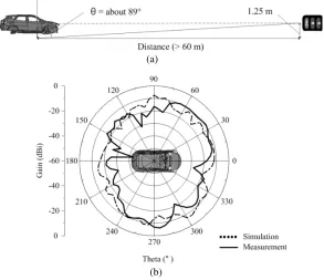
To estimate the radiation characteristics of the RKE antenna, it is assumed that the transmitting handheld device is located at a distance of 60 m with a height of about 1.25 m from the ground, thus the antenna gain is observed at θ = 89◦ (about 88.8◦ if the distance is 60 m), as shown in Fig. 7(a). The radiation pattern is measured in a semi-anechoic chamber, and the measured pattern is compared to the simulation conducted with an assumption that the ground is covered by concrete (εr = 7,
Figure 6. Simulated and measured reflection coefficients.
(a)
(b)
Figure 7. Simulation conditions and results. (a) Simulation conditions of the radiation pattern. (b) Simulated and measured radiation patterns at 434 MHz.
3. PERFORMANCE EVALUATION
3.1. Formulations of the Reading Distance Estimation
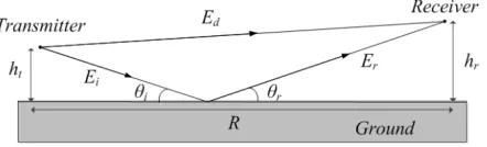
Figure 8 shows the geometry of the two-ray propagation model. A transmitter and a receiver are separated by R, and the transmitted signal is delivered to the receiver through radio waves along a direct path (Rdirect) and an indirect path (Rindirect) that can be calculated by Eqs. (1) and (2), respectively [19].
Rdirect = R
1 +
ht−hr
R
2
≈R
1 +1
2
ht−hr
R
2
Figure 8. Flow chart of the estimation method.
Rindirect = R
1 +
ht+hr
R
2
≈R
1 + 1
2
ht+hr
R
2
(2)
If the value of R is much greater than the sum of the transmitter height (ht) and the receiver height
(ht) (i.e., R ht+hr), then the phase difference (Δφ) caused by the path difference (ΔR) can be
written as Eqs. (3) and (4), respectively.
ΔR = |Rdirect−Rindirect|= 2hthr
R (3)
Δφ = ΔR2π λ =
4πhthr
λR (4)
Eqs. (5) and (6) show vertical and horizontal reflection coefficients that are affected by the relative permittivity (εr) of the ground and the incident angle (θi) of the wave [20].
Γv = εrsinθi− √
εr−cos2θi
εrsinθi+
√
εr−cos2θi
(5)
Γh = sinθi− √
εr−cos2θi
sinθi+
√
εr−cos2θi
(6)
We can also include the effect of surface roughness by considering the root-mean-square (RMS) height (hrms) of the ground, as presented in Eq. (7), and each reflection coefficient is multiplied by the surface
roughness Sr [20].
Sr =e−
22πhrmsλsinθi2
(7)
wherehrms represents the surface irregularity that can be computed as
hrms= λ
8 sinθi
(8)
Since it is assumed that the RKE antenna used in our approach is vertically polarized, only the vertical reflection coefficient is taken into account for further derivations (Γ = Γv·Sr). Thus, the electric field
strengths of both the direct (|Ed|) and indirect (|Er|) paths can be expressed as
Ed =
ηPtGt
4πR2direct (9)
Er =
ηPtGt
4πR2
indirect
Γej(Δφ) (10)
whereηis the intrinsic impedance of free space,Pta transmitting power, andGtthe transmitter antenna
gain [21]. Thus, the total electric field strength (|Etot|) can be written as
Etot = Ed+Er =Ed
1 + Γej(Δφ)
=Ed(1 + Γ (cos (Δφ) +jsin (Δφ))) (11)
Since the effective aperture of the receiving antenna can be expressed by the receiving antenna gain (Gr) and the wavelength (λ), as shown in Eq. (13), the total average received power (Pr) can be derived
as Eq. (14).
Aer = Grλ
2
4π (13)
Pr = |Etot|
2
η Aer=|Ed|
2Grλ2
4πη
1 + Γ2+ 2Γ cos (Δφ)
= PtGtGr
λ
4πRdirect
2
1 + Γ2+ 2Γ cos (Δφ) (14)
Rdirect can be found as:
Rdirect =
Pt
PrGtGr
λ
4π
2
(1 + Γ2+ 2Γ cos (Δφ)) (15)
Rn =
Pt
Pr,n−1GtGr,n−1·
λ
4π
2
·
1 + Γ2n−1+ 2Γn−1cos
4πhthr
λRn−1
−(ht+hr)2 (16)
Thus the reading distance can be computed by using an iterative process, as presented in Eq. (16), where
nindicates the iteration index. In detail, the distance of the current iteration (Rn) is calculated using
information from the previous iteration, i.e., Pr,n−1, Gr,n−1, Γn−1, and Rn−1, and the process stops when the received power of the previous iteration (Pr,n−1) is less than the noise floor of the system, which is defined as a threshold power value determining the system reading distance.
Figure 9. Specifications of the RKE system for the two-ray propagation model.
3.2. Measurement Results
Figure 9 shows the measurement setup to verify the accuracy of the proposed simulation-based approach. It is assumed that the transmitting antenna has an average gain of−7 dBi, and its transmitting power is−16 dBm with a threshold power level of−110 dBm. We also assume that the heights of the handheld device and the receiving RKE antenna are 1.25 m and 0.95 m, respectively, from the ground.
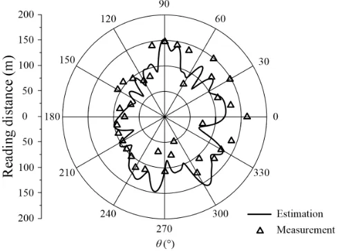
Figure 10 exhibits a comparison between the estimated reading distance, indicated by a solid line, and the measurement, indicated by triangular markers. The measured reading distance shows an average value of 110 m and is similar to the estimated value of 108 m, which implies that the proposed simulation-based approach can replace the measurement-based method with the average estimation error of 2 m.
4. CONCLUSION
We have investigated the systematic simulation-based approach to estimate the reading distance of an RKE system as a replacement for the measurement-based method. In our simulation, the RKE antenna and the vehicle structure were modeled in the EM simulation to estimate antenna characteristics, such as reflection coefficients, radiation patterns, and antenna gains. For more accurate results, we also included detailed interior structures, such as body frames, steering wheels, and vehicle audio systems. In addition, the effects of ground properties, antenna polarizations, orientations and heights of handheld devices were also considered in our approach with the two-ray propagation model. The estimated reading distance was 108 m and was similar to the open-site measurement of 110 m, which confirmed that the proposed approach was suitable for use as a replacement for the current measurement-based method with an average estimation error of less than 2 m.
ACKNOWLEDGMENT
This research was supported by Civil Military Technology Cooperation (CMTC) and the Basic Science Research Program through the National Research Foundation of Korea (NRF) funded by the Ministry of Education (No. 2015R1A6A1A03031833).
REFERENCES
1. Dar, K., M. Bakhouya, J. Gaber, M. Wack, and P. Lorenz, “Wireless communication technologies for ITS applications,” IEEE Commun. Mag., Vol. 48, No. 5, 156–162, May 2010.
2. Leen, G., D. Heffernan, and A. Dunne, “Digital networks in the automotive vehicle,” IEEE Computer Control Eng. Journal, Vol. 10, No. 6, 257–266, Dec. 1999.
3. Leen, G. and D. Heffernan, “Expanding automotive electronic systems,” IEEE Computer, Vol. 35, No. 1, 88–93, Jan. 2002.
4. Alrabady, A. I. and S. M. Mahmud, “Analysis of attacks against the security of keyless-entry systems for vehicles and suggestions for improved designs,” IEEE Trans. Veh. Technol., Vol. 54, No. 1, 41–50, Jan. 2005.
5. Brooks, R., S. Sander, J. Deng, and J. Taiber, “Automobile security concerns,”IEEE Veh. Technol. Mag., Vol. 4, No. 2, 52–64, June 2009.
6. Oh, K., B. Kim, and J. Choi, “Novel integrated GPS/RKES/PCS antenna for vehicular application,”IEEE Microw. Wireless Compon. Lett., Vol. 15, No. 4, 244–246, Apr. 2005.
7. Rabinovich, V., B. Al-Khateeb, B. Oakley, and N. Alexandrov, “Small printed meander symmetrical and asymmetrical antenna performances, including the RF cable effect, in the 315 MHz frequency band,” Microw. Opt. Technol. Lett., Vol. 48, No. 9, 1828–1833, Sep. 2006.
9. Al-Khateeb, B., V. Rabinovich, B. Oakley, and N. Alexandrov, “Compact planar antennas for short-range wireless automotive communication,” IEEE Trans. Veh. Technol., Vol. 55, No. 4, 1425–1435, Jul. 2006.
10. Galehdar, A., D. V. Thiel, and S. G. O’Keefe, “Tapered meander line antenna for maximum efficiency and minimal environmental impact,”IEEE Antenna Wireless Propag. Lett., Vol. 8, 244– 247, 2009.
11. Rabinovich, V., B. Al-Khateeb, B. Oakley, and N. Alexandrov, “A signal and noise-measurement procedure for an antenna/RF receiver combination in a short-range automotive communication system,” Microw. Opt. Technol. Lett., Vol. 47, No. 2, 116–119, Oct. 2005.
12. Abou-Jaoude, R. and E. K. Walton, “Numerical modeling of on-glass conformal automobile antennas,”IEEE Trans. Antennas Propag., Vol. 46, No. 6, 845–852, Jun. 1998.
13. Muccioli, J. P. and S. S. Awad, “The electromagnetic environment of an automobile electronic system,” IEEE Trans. Electromagn. Compat., Vol. 29, No. 3, 245–251, Aug. 1987.
14. FEKO Suite 6.2, EM Software and Systems, http://www.feko.info, accessed May 5, 2014.
15. Schaffner, J., H. Song, A. Bekaryan, H. Hsu, M. Wisnewski, and J. Graham, “The impact of vehicle structural components on radiation patterns of a window glass embedded FM antenna,” IEEE Trans. Antennas Propag., Vol. 59, No. 10, 3536–3543, Oct. 2011.
16. AWE Communications, Wave Propagation and Radio Network Planning, http://www.awe-comm unications.com, accessed May 5, 2014.
17. Bourdi, T., J. E. Rhazi, F. Boone, and G. Ballivy, “Modelling dielectric-constant values of concrete: an aid to shielding effectiveness prediction and ground-penetrating radar wave technique interpretation,” Journal of Physics D: Applied Physics, Vol. 45, No. 40, 1–12, 2012.
18. Filali, B., F. Boone, J. Rhazi, and G. Ballivy, “Design and calibration of a large open-ended coaxial probe for the measurement of the dielectric properties of concrete,” IEEE Trans. Microw. Theory Techn., Vol. 56, No. 10, 2322–2328, Oct. 2008.
19. Akka¸slı, C., Methods for Path Loss Prediction, 1st Edition, Linnaeus University V ¨AXJ ¨O, 2009. 20. Mahafza, B. R., Radar Systems Analysis and Design Using Matlab, 3rd Edition, A Chapman &
Hall book Boca Raton, 2012.