Field-Excited Flux Switching Motor Design, Optimization and
Analysis for Future Hybrid Electric Vehicle
Using Finite Element Analysis
Erwan Sulaiman1, *, Faisal Khan1, and Takashi Kosaka2
Abstract—Design, optimization, and performance analysis of a three-phase field-excited flux switching (FEFS) motor to be employed for the future hybrid electric vehicle (HEV) drive applications is investigated in this paper. The stator of designed motor made of electromagnetic steels is composed of unique field mmf source and armature coils while a rotor is made of iron stack. This design has been evaluated in order to achieve power and torque density higher than 3.50 kW/kg and 210 Nm, respectively, so as to compete with the interior permanent magnet synchronous (IPMS) motor commonly installed in HEV. Given its robust rotor structure, the maximum achievable motor speed went up to 20,000 rpm. To perfect the motor design, a deterministic optimization approach was applied to meet the stringent performance requirements. In addition, experimental analyses were carried out to confirm the effectiveness of the proposed motor. Positively, the proposed FEFS motor has proved to be a suitable candidate of non-permanent magnet motor for efficient and safe HEV drive.
1. INTRODUCTION
Driven by concern about the environment, automakers, government, and automobile users retain a keen interest in electric vehicle (EV) and hybrid electric vehicle (HEV), which makes the research in this area intriguing. As electric motors are the core of electric propulsion system, initiatives to develop advanced, state-of-the-art electric motors have been undertaken [1, 2]. So far to reduce environment pollution among other benefits, HEV is known to be the most promising green vehicle using combination of internal combustion engine (ICE) and one or more electric motors. DC motor, induction motor (IM), switch reluctance motor (SRM), and permanent magnet synchronous (PMS) motor are potential candidates of electric motors for HEV drives, as shown in Fig. 1. Among them, DC motor has the ability to operate only at DC supply and therefore widely used in HEV. Besides, the DC motor can be simply controlled based on the orthogonal disposition of field and armature mmf. However, the maintenance problem due to the use of commutator and brush, DC drive encounters renders it unsuitable for HEV and less reliable for maintenance-free drive [3–6].
Researchers have investigated the possibility of IM — a non permanent magnet (PM) motor — among brushless machine for electric propulsion system. Cage IM is acknowledged as the most possible candidate due to reliability, cost-effectiveness, ruggedness, and capability of operating in hostile environment. Nonetheless, its relatively low efficiency in the low speed, light load region of HEV may affect fuel consumption and degrade system efficiency. Additionally, IM drive has such problems of low torque density and low power factor which contradict the requirement for high electric loading. These stringent conditions particularly turn into major disadvantages of IM, thus eliminating it from being a suitable candidate for electric propulsion system of HEV [7–9].
Received 25 September 2016, Accepted 27 October 2016, Scheduled 6 December 2016 * Corresponding author: Erwan Bin Sulaiman ([email protected]).
1 Universiti Tun Hussein Onn Malaysia, Parit Raja, Batu Pahat, Johor 86400, Malaysia.2Nagoya Institute of Technology (NITech),
Armature coil
PM Stator
Rotor Rotor
Armature coil
PM
Rotor Armature coil
Stator
(a) (b) (c) (d)
Figure 1. Four major candidates for HEV drive, (a) DC motor, (b) IM, (c) SRM, (d) IPMS motor.
Meanwhile, SRM, a non-PM motor, is familiarly recognized to have great potential for HEV applications. Its merits include low manufacturing cost, fault tolerance, simple and rugged construction, simple control, and much better torque-speed characteristics than IM. Overall, SRM has the ability to operate at very wide constant power range. However, it has disadvantage and unsuitable for HEV propulsion system due to large torque ripples, vibration problem, acoustic noise which imposes excessive bus current ripple, special converter topology, and electromagnetic interference that causes additional noise [10–14].
In contrast, IPMS motor is brushless machine and has various attractive characteristics compared with other machines installed in HEV. Hitherto, IPMS motor retains its competitive advantage over other electric motors concerning HEV’s electric propulsion system. In fact, the renowned automakers such as BMW, GM, Renault-Nissan, Toyota, Honda have long adopted IPMS motor in consideration of its advantages of small size, light weight, high power density, high reliability, high torque, and high efficiency. In 2009, IPMS motor was successfully installed on Toyota Prius [15]. This can be verified by historical development in the power density of main traction motor installed on Toyota HEVs. Over the years, power density of IPMS motor has been improved by at least five times, with enhancement more conspicuous than its first appearance in Toyota Prius in 1997 [16]. Although it is very hard to ameliorate the torque density of a motor, integrating a reduction gear has enabled elevation of the axle torque necessary for propelling large vehicle. Along this line, one effective strategy to increase the power density of a motor would be to combine high-speed motor with reduction gear. For dual-excitation switched-flux (DESF) motor, the PM volume is reduced by half of that employed in IPMS motor, yet maintaining the power density at maximum value [17]. Nevertheless, compared with dual-excitation switched-flux (DESF) motor, IPMS motor is heavier because it consists of more components and materials. In this regard, dual-excitation FSM motor prides itself on lower cost and smaller size.
However, with the growing demand for EVs and HEVs, the annual consumption of rare-earth PM
by IPMS motor has increased accordingly. This causes the prices of Neodymium (Nd) and Dysprosium
(Dy) — an essential additive to provide the rare-earth PM with high coercivity — to rise markedly.
Together, they raise serious concerns about soaring cost, security matters, and supply shortages. Hence, continuous research effort to develop electric motors with robust rotor structure and high power density without relying on rare-earth magnet is of the utmost importance [18].
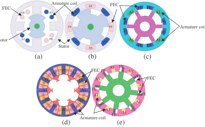
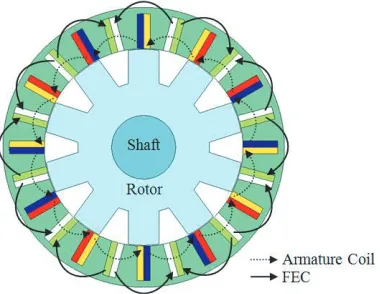
To overcome the above mentioned obstacles, PM of DESF motor can be eliminated by FE coil excitation only on the stator, to form FEFS motor as shown in Fig. 2. Briefly, the principle of operation of FEFS motor is based on switching the flux polarity linking with the armature coil windings by
altering the rotor position. Single-phase FEFS motor with 4 stator slots and 2 rotor poles
(4S-2P) composed of a FE coil, fully-pitched windings on the stator, and a toothed rotor structure is
demonstrated in Fig. 2(a) [19]. As clearly illustrated, the two armature coils and a FE coil are
FEC
Armature coil
FEC FEC
Armature coil Armature coil
FEC
FE FE
FE
FE
FE FE FE FE
A1 A1
A1
A1
A1 A1
A1 A1
Stator Rotor
FE FE
FE
FE
FE FE
A1 A1
A1
A1 A1
A1
A1 A1
A1 A1 FE
FE
FE
FE
FE FE FE
FE
(a) (b) (c)
(d) (e)
Figure 2. (a) Single-phase 4S-2P FEFS motor, (b) single-phase 8S-4P FEFS motor, (c) single-phase FEFS motor with salient rotor, (d) single-phase 12S-6P FEFS motor, (e) single-phase 8S-8P FEFS motor.
Another example of single-phase 8S-4P FEFS motor is shown in Fig. 2(b) [22]. When field current is applied to the field winding in four of the slots, four-pole magnetic field is formed. The armature winding in the remaining four slots is pitched over two stator teeth. A set of four stator poles carry flux while the rotor position is determined by current’s direction in the armature winding. As FE coil is excited by current of single polarity, it will have direct connection either in parallel or in series with DC supply of power converter which feeds bipolar current into the armature winding. The theory underlying this design is explained in [23], where single-phase 8S-4P FEFS motor is compared with IM and demonstrates higher output power density as well as better efficiency. Nonetheless, the single-phase FEFS motor has some demerits fixed direction of rotation, large torque ripple, low starting torque, and overlapping windings between FE coil and armature coil. Two single phase FEFS motor topologies with DC field and armature windings having the same pitch of two slot-pitches and different coil-pitches of one and three slot-coil-pitches, respectively, have been discussed [24]. It is shown that the iron loss of FEFS motor has been reduced, thus increasing the efficiency. Nonetheless, these topologies have problem of less efficiency due to overlap windings as illustrated in Fig. 2(c) than single-phase FEFS motor with non-overlap windings. Single-phase 12S-6P FEFS motor with segmental rotor has been designed for high density air-conditioner and discussed in [25]. Due to non-overlapping windings, the proposed motor has less copper losses as shown in Fig. 2(d) than single-phase FEFS motor with salient rotor. Although single-phase 12S-6P FEFS motor has the capability to produce high output power, it is unsuitable for high-speed applications due to non-robust segmental rotor. Performance analysis of single-phase 8S-8P FEFS motor, depicted in Fig. 2(e), is discussed in [26]. The proposed motor has high cogging torque, overlap armature and field windings which make it not suitable to be applied to any electrical equipment.
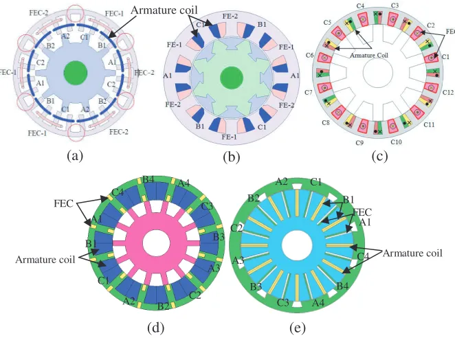
To meet the rigid performance requirements, a three-phase 24S-10P FEFS motor has been built upon the existing 24S-10P PMFS motor, by replacing PM with FE coil at the stator and arranging FE coil windings at the upper half layer of armature coil slots as illustrated in Fig. 3(a) [27]. It is noticeable that FE Coil-1 and FE Coil-2 are arrayed along with alternate DC current source polarities to produce two flux polarities, similar to PM polarity of 12S-10P PMFS motor. The main disadvantage of this configuration is that the isolated and unused stator teeth, as highlighted by red circles, decrease the overall motor performance.
Armature coil
A1 B1 C1 B2
C2
A3
B3
C3 A4 B4
C4 A2
FEC
Armature coil FEC
Armature coil A1
B1
C1
A2 B2 C2 A3
B3 C3 A4 B4 C4
(a) (b) (c)
(d) (e)
Figure 3. (a) Three-phase 24S-10P FEFS motor, (b) 12S-8P segmental rotor FEFS motor, (c) 24S-10P FEFS motor with single FE coil, (d) 12S-14P FEFS motor with toroidal DC winding, (e) outer rotor FEFS motor.
windings. This design has noteworthy gains over other designs as it consumes less conductor materials, accordingly enhances the overall efficiency due to reduction of copper loss. However, the motor is not suitable for high-speed applications due to less robust structure. FEFS motor with single polarity FE coil was discussed in [29], as illustrated in Fig. 3(c). FEFS motor with single polarity FE coil has advantages of low copper loss and less leakage flux than dual FE coil windings. The field-weakening capability of FEFS motor is improved using toroidal dc field winding, as shown in Fig. 3(d) [30]. Although the proposed machine has generated high torque, the copper losses will be high due to overlapping windings. In recent years, in-wheel motor for EV drive train system raises the challenge for motor design and is increasingly considered due to its numerous advantages of high efficiency, no mechanical axis and independent wheel controllability. Additionally, more cabin space is available due to the elimination of differential and mechanical axis conventionally used in most of existing HEV. In view of the fact that the outer-rotor configuration is more suitable for direct drive, the PMFS motor with outer-rotor has been explored only for light EV applications [31]. It provides essentially high torque at low speed and sinusoidal back-electromotive force (emf). However, it is difficult to control flux of PMFS motor which requires field weakening flux at high-speed conditions. 12S-10P outer rotor FEFS motor has been investigated conventionally and discussed in [32], as illustrated in Fig. 3(e). Salient rotor structure with high mechanical strength and less cost due to no PM are clear advantages of this machine while overlapping windings arrangements create problem of high copper losses. It can be concluded from the discussions that all motors have various problems that must be resolved for their practical implementation.
experimental outcomes confirmed that the proposed motor is a suitable candidate of non-PM traction motor for HEV drive.
2. DESIGN SPECIFICATIONS AND RESTRICTIONS FOR TARGETED HEV APPLICATIONS
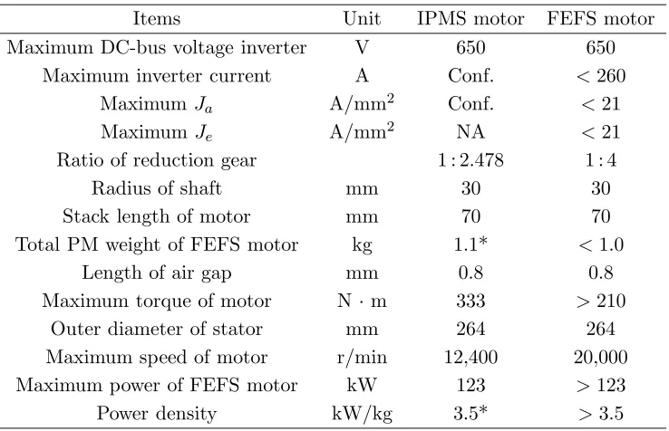
The design specifications and restrictions of FEFS motor for HEV applications are shown in Table 1, taking the estimated and available values of IPMS motor in [11] as reference. Assuming that there is only one water cooling system, the current densities of FE coils and armature windings are respectively set to the highest values of 21 A/mm2 and 21 Arms/mm2. The stack length of stator core and the outer diameter of stator are identical to those of IPMS motor. Given the laminated iron core, the rotor structure of the proposed motor is expected to be mechanically strong for high-speed rotation. Indeed, the motor is capable to operate at maximum speed up to 20,000 r/min. As for the required maximum torque of 210 Nm, it is decided by realization of maximum axle torque — comparable to that of IPMS motor — via reduction gear at a ratio of 4 : 1. Similar to that of IPMS motor, the maximum output power is set to be greater than 123 kW while the calculated weight of motor is less than 35 kg, yielding the highest power density of 3.5 kW/kg. In this investigation, a commercial FEA solver, JMAG released by JSOL Corporation, is used for 2D-FEA. The partial differential equation based on Maxwell’s equations explaining the physical behaviour of the magnetic field distribution in thex-y plane cross section of the machine solution domain discussed in [34, 35] can be stated as,
∂ ∂x
ν∂Bz ∂x
+ ∂
∂y
ν∂Bz ∂y
=−Jz (1)
whereJz,Bzare the axial(z) components of the total current density and magnetic vector potential, and ν is the magnetic reluctivity of the medium. Meanwhile, the current density, Jz, in Eq. (1) is uniformly distributed in the field and armature windings. The whole procedure to model the electric machines using finite element method is discussed in [36]. The finite element computations are performed to analyse the performance of proposed motor and further validated experimentally.
Table 1. Design specifications and restrictions of FEFS motor.
Items Unit IPMS motor FEFS motor
Maximum DC-bus voltage inverter V 650 650
Maximum inverter current A Conf. <260
Maximum Ja A/mm2 Conf. <21
MaximumJe A/mm2 NA <21
Ratio of reduction gear 1 : 2.478 1 : 4
Radius of shaft mm 30 30
Stack length of motor mm 70 70
Total PM weight of FEFS motor kg 1.1* <1.0
Length of air gap mm 0.8 0.8
Maximum torque of motor N ·m 333 >210
Outer diameter of stator mm 264 264
Maximum speed of motor r/min 12,400 20,000
Maximum power of FEFS motor kW 123 >123
3. CONFIGURATION OF INITIAL 12SLOT-10POLE FEFS MOTOR
Figure 4 displays the cross-sectional view of initial FEFS motor design, with black and dotted lines representing FE coil and armature coil, respectively. Visibly, the motor has 10 rotor poles and 12 armature coil slots in the stator. Each of the twelve FE coil slots is arranged unvaryingly in the middle of every corresponding armature coil slot. Technically, DC is applied to FE coils to create 6 south poles interspersed with 6 north poles. At a standstill, the generated magnetic fields circulate around rotor poles to form a complete cycle. As the rotor rotates, the polarity of magnetic fields is switched alternately by chasing the rotor pole position. The three-phase armature coils are quartered at regular intervals in the stator body, as represented by red-yellow-blue color in the figure. When the rotor begins rotating, the fluxes produced by mmf of FE coils start linking with armature coils. When the rotor rotates through 1/10 of a revolution, the flux linkage with armature coil makes just one electrical cycle, and thus, the induced voltage frequency in armature coil turns into ten times of the mechanical rotational frequency. As with SRM, the designed motor is suitable as well as robust for high-speed operation as long as its rotor consists only of single-piece iron core.
In this research study, the selection of 12slot-10pole motor is justified by the following reasons: First, it is considered the best minimum slot-pole combination to avoid odd rotor pole number, which leads to unbalanced pulling force [37]. Second, get around much torque ripples, as in the case of 8-pole or 4-pole machine [38]. Third, strike a good balance between stator and rotor’s tooth widths for reducing unavoidable torque pulsation. On the whole, the choice of preliminary FEFS motor design is based on the general suppositions as follows [17, 27]:
(i) The split ratio (rotor outer radius divided by stator outer radius) for an electric motor is 0.6 to 0.7. (ii) The rotor outer radius for FEFS motor is set to be 92.4 mm, that is 70% of stator outer radius of
132 mm.
(iii) The opening angles of armature coil slots, FE coil slot, and stator teeth are set identically as 7.5◦. All FE coil slot and armature coil slots are rectangular in shape having the same slot depth. These conditions avoid magnetic saturation in the teeth, ensure sufficient mmf contributed jointly by armature coils and FE coil while facilitating design optimization.
(iv) The opening angle for each rotor pole is calculated by dividing the sum of opening angles of stator teeth by the number of rotor poles. In the case of 12slot-10pole motor, the opening angle for every rotor pole is set to be 18◦, which is one-tenth of the sum of opening angles of stator teeth of 180◦. It is important to note that narrower opening angle of a rotor pole will give rise to magnetic saturation in rotor teeth. In contrast, too wide an opening angle will make fluxes flow more easily from the stator, during which some of the flux movements may create negative torque.
(v) The stator back yoke thickness is set as 6 mm — half of inner tooth width of stator — to assume that the flux flowing in the tooth is divided into two adjoining yokes.
Figure 4. Top view of initial 12slot-10pole FEFS Motor design.
(vi) The rotor pole depth is set to be 30.8 mm, that is one-third of rotor outer radius, ensuring sufficient thickness of rotor back yoke whereas avoiding flux leakage due to fringing.
4. DESIGN PARAMETERS AND PROCEDURE
Drived performance parameters of initial FEFS motor design are computed and evaluated at the
beginning of the design process. The power and maximum torque are 74.1 kW and 154.5 Nm,
respectively, which are far from the required values. In an effort to ensure that performance targets are met, free design parameters are defined as D1 to D7 (see Fig. 5). The deterministic optimization method proposed by [17] is applied to update the design parameters repetitively until all performance
targets are achieved. To start with, the rotor design parameters — D1, D2, and D3 — are updated
while the stator design parameters — D4,D5,D6, and D7 — remain unaltered.
In theory, torque is directly proportional to the square of radius of rotorD1 when specific magnetic and electric loadings are kept constant. In order to achieve the maximum torque, the radius of rotorD1 becomes the most significant parameter to be manipulated. Meanwhile, the other design parameters
— D2 to D7 — are unchanged, and they vary according to displacement of D1. Once the optimum
D1 value that generates the highest torque is found, it is kept constant while rotor pole width (D2) and rotor depth (D3) are updated. Subsequently, the optimum values ofD1,D2, and D3 that produce
the highest torque are kept unchanged, whereas the stator parameters, FE coil D4 and FE coil D5,
are altered while keeping fixed values of D6 and D7 as set initially. The finest combination of D4
and D5 that brings about target values — in terms of power capability and maximum output torque
— is determined under specific mmf of armature windings corresponding to the assigned D6 and D7.
Lastly, the design parametersD6andD7are altered though the foregoing parameters are kept constant.
These steps result in a set of seven design parameters D1 to D7 which enable FEFS motor to achieve
well-balanced performance under the limitations of the given maximum voltage, current, and current densities. For the sake of perfection, the aforementioned design procedure is repeated by varyingD1 to
D7 until the targeted power and torque are attained. Throughout the optimization process of design,
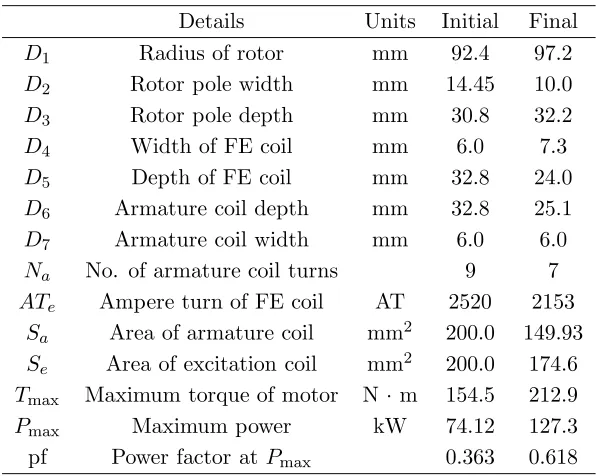
the air gap length is set as 0.8 mm. To ensure smooth flux flow around the slots and consideration of the manufacturing constraint, the circled corners in Fig. 5 are reshaped with circular line in final design. Fig. 6 shows the cross-sectional view of final FEFS motor, while Fig. 7 shows the comparison of flux vector diagram under maximum current densities of armature (Jamax) and FE coil (Jemax) between initial and final FEFS motor designs. Evidently, high flux density saturation is observed at stator back yoke as compared with the final design that has been mitigated. In reality, the stator back yoke thickness in the final motor design has been expanded in order that much flux can flow easily without any hindrance to boost the maximum torque value. Table 2 summarizes the comparison of design parameters between initial and final designs.
Figure 6. Cross-sectional view of final 12S-10P design.
(a) (b)
Flux saturation Less flux saturation
Table 2. Parameters of initial and final 12S-10P FEFS motor designs.
Details Units Initial Final
D1 Radius of rotor mm 92.4 97.2
D2 Rotor pole width mm 14.45 10.0
D3 Rotor pole depth mm 30.8 32.2
D4 Width of FE coil mm 6.0 7.3
D5 Depth of FE coil mm 32.8 24.0
D6 Armature coil depth mm 32.8 25.1
D7 Armature coil width mm 6.0 6.0
Na No. of armature coil turns 9 7
ATe Ampere turn of FE coil AT 2520 2153
Sa Area of armature coil mm2 200.0 149.93
Se Area of excitation coil mm2 200.0 174.6
Tmax Maximum torque of motor N ·m 154.5 212.9
Pmax Maximum power kW 74.12 127.3
pf Power factor at Pmax 0.363 0.618
5. PERFORMANCE PREDICTION FOR 2D-FEA-BASED FINAL FEFS MOTOR DESIGN
5.1. Distribution of Field Flux by FE Coil Excitation and Induced Voltage Waveforms
The finite element computations based on Eq. (1) are performed on the full geometry of final FEFS motor design with appropriate boundary conditions. The field flux distribution generated by FE coil excitation has the maximum current density (Jemax) at four electrical positions of rotor, as shown in Fig. 8. In accordance with rotor position displacement, the polarities of field fluxes linked with three-phase armature coils are switched, thereby realizing the term “flux switching”.
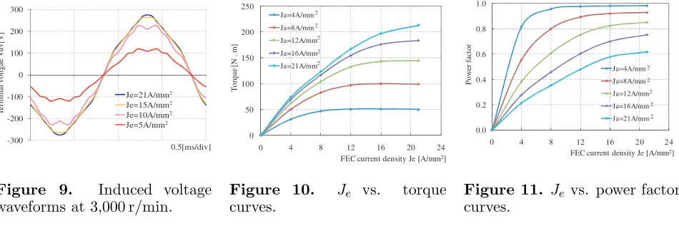
The induced EMF waveforms due to various FE coil current densities (Je), at speed of 3000 r/min,
are presented in Fig. 9. Note that waveform amplitudes at FE coil excitation below 10 A/mm2 increase
linearly with increasing current densities, whereas those at FE coil excitation above 15 A/mm2 are
highly saturated. Nonetheless, this high magnetic saturation above 15 A/mm2 contributes to power
factor improvement so that the maximum power capability is increased.
(a) (b) (c) (d)
5.2. Torque and Power Factor Versus Ja and Je Curves
Figure 10 reveals torque versus FE coil current density (Je) curves at different armature winding current densities (Ja). AtJabelow 12 Arms/mm2, the torque value becomes constant as it attains a certain value in spite of any additional increment inJe. This indicates that a sound balance between mmf of armature
winding and FE coil requires to be considered in order to obtain the desired torque and minimize copper losses in the FE and armature coils as well. A qualitative justification for this phenomenon is that when the motor is operated by high field winding mmf and less armature winding mmf, a negative torque will produce, and accordingly, the increase in FE coil mmf cancels out the increase of positive torque. Conversely, when less FE coil mmf and extremely high armature winding mmf are fed to the motor, a negative torque is developed and as a result, any increase in positive torque will oppose the increase of armature winding mmf.
Figure 11 portrays howJe changes with power factor in response to varyingJa. Firstly, the power factor is calculated by assuming that the voltage drop due to resistance is negligible relative to the induced EMF. Noticeably, the power factor is improved by larger mmf of FE coil, even when very large mmf of armature winding is supplied. As discussed before, this is an outcome of armature reactionLqiq produced by armature winding mmf being saturated in accordance with severe magnetic saturation resulting from greater FE coil excitation. As with torque curves, power factor curves manifest the same trend. Specifically, when maximizing power factor, a good balance between FE coil mmf and armature winding mmf must be maintained so as to achieve the reference torque under specified speed. Moreover, as the inverter conduction loss depends on power factor, the current commands for both armature winding and FE coil at the given operating points have to be carefully optimized so that the motor is controlled with the highest system efficiency.
-300 -200 -100 0 100 200 300 T er m in al v o lt g ae V u v [V ] 0.5[ms/div] Je=21A/mm2 Je=15A/mm2 Je=10A/mm2 Je=5A/mm2
Figure 9. Induced voltage waveforms at 3,000 r/min.
0 50 100 150 200 250
0 4 8 12 16 20 24
T o rq u e [ N . m]
FEC current density Je [A/mm2] Ja=4A/mm2 Ja=8A/mm2 Ja=12A/mm Ja=16A/mm Ja=21A/mm 2 2 2
Figure 10. Je vs. torque curves. 0.0 0.2 0.4 0.6 0.8 1.0
0 4 8 12 16 2 4
P o w er fac to r
FEC current density Je [A/mm2] Ja=4A/mm2 Ja=8A/mm2 Ja=12A/mm Ja=16A/mm Ja=21A/mm 0 2 2 2 2
Figure 11. Je vs. power factor curves.
5.3. Torque and Power Versus Speed Curves
for IPMS motor [40], while the proposed FEFS motor has power density of 127.3 kW/26.03 kg, greater than IM, SRM and IPMS motor, respectively. Moreover, the final FEFS motor design has high torque density compared to 12S-8P segmental rotor FEFS motor due to saturation of rotor segments as well as high torque density than 12S-14P FEFS motor with toroidal DC winding due to limited torque generation as the field flux produced by FE coil close to outer surface of stator goes through outside of the stator instead of the rotor. The final FEFS motor design has 67% high torque density compared to outer rotor FEFS motor [41].
5.4. Motor Efficiency and Loss Predictions
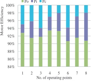
In Fig. 13, No. 1 is denoted as the operating point at base speed (with maximum torque) while No. 2 indicates the operating point at a high speed of 15,000 r/min, respectively. Moreover, to evaluate the performance at light-load driving conditions, several frequently encountered operating points, designated as No. 3 to No. 8, are marked for loss predictions and motor efficiency. The copper losses of armature windings and FE coil are analytically examined based on their geometries, by considering the end coils length effect at 100C◦ of coil temperature. Additionally, the losses of iron — including hysteresis and eddy current losses — are computed by 2D-FEA using the 35H210 loss data sheet provided by the solver.
Figure 14 shows the summary of a detailed analysis of iron losses, copper losses and predicted
efficiency for the final FEFS motor design. Briefly, Pi and Pc are the sums of iron and copper losses,
respectively, while Po is the output power. The motor efficiency reaches 92.8% at operating point
No. 1 — with an output power of 127.3 kW while the copper and iron losses are 6.75 kW and 3.09 kW, respectively. At operating point No. 2, where the output power is 130 kW, and the combined copper and iron losses are 12.1 kW at 15,000 r/min, the motor attains efficiency of 91.5%.
Furthermore, under relatively high average torque of 100 Nm mentioned as operating points No. 3 to No. 5, the average FEFS motor efficiency is slightly above 92% while for operating points No. 6 to No. 8 under 50 Nm torque, the motor efficiency is averagely 91%. This degradation in efficiency is probably contributed by high iron losses rather than copper losses. Thus, the current commands for FE coil and armature windings must be optimized through reduction of iron losses in order to achieve better motor efficiency.
0 20 40 60 80 100 120 140 160 180 0 50 100 150 200 250 300 350
0 4000 8000 12000 16000 20000 P [kW] T [Nm]
speed [r/min] Torque [FSM]
Torque [IPMSM]
Figure 12. Comparison of
torque and power vs. speed
characteristics between FEFS motor and IPMS motor.
0 35 70 105 140 175 0 50 100 150 200 250
0.0 2.5 5.0 7.5 10.0 12.5 15.0 17.5 20.0
P o we r[k W] To rq u e [N ⋅ m]
motor speed [kr/min] Operating poinits for loss and efficiency predictions
1
2 3 4 5
6 7 8
Figure 13. Efficiency and motor losses at operating points.
84% 86% 88% 90% 92% 94% 96% 98% 100%
1 2 3 4 5 6 7 8
M o to r Ef fic ie n c y
No. of operating points Po Pi Pc
Figure 14. Operating points for efficiency and loss predic-tions.
6. EXPERIMENTAL RESULTS
Test motor Torque measurement system
Dynamometer
(a) (b) (c) (d)
Figure 15. Photographs of test motor, (a) assembly of stator core, (b) assembly of stator, (c) assembly of stator and rotor, (d) Experimental bench.
24 slots. The entire motor assembly completed with the rotor core is displayed in Fig. 15(c). The prototype of the final FEFS motor is enclosed by water cooling jacket and experimental bench for data measurement is illustrated in Fig. 15(d).
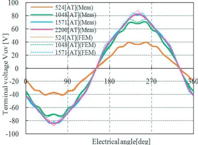
6.1. Measured Induced Voltage Waveforms at 1000 r/min
Under the conditions of all three-phase armature windings being in an open circuit and operated at a speed of 1,000 r/min, the changes of induced voltage waveforms with varying FE coil mmf are measured. The comparison between 2D-FEA-computed and measured induced voltage waveforms is shown in Fig. 16. The twelve FE coils are connected in series, and there are 44 turns per FE coil. The mmf per FE coil — in the unit of AT — is calculated from the DC current of FE coil multiplied by 44 turns. To be precise, the mmf of FE coil at 524 AT, 1048 AT, 1571 AT, and 2200 AT corresponds respectively to FE coil current density of 5 A/mm2, 10 A/mm2, 15 A/mm2, and 21 A/mm2. Positively, the 2D-FEA-computed and measured induced voltage waveforms are found to be in good agreement.
6.2. Armature Coil Current Versus Torque Characteristics
The curves of armature coil current versus measured torque are plotted in Fig. 17. During the test, the
armature current varies from 0 to 154.8 Arms, that is about 60% of the maximum armature current of
260 Arms achieved at the design stage — a constraint attributable to the limit of maximum inverter
current. As for FE coil mmf, its variation ranges from 0 to 2200 AT, as in the induced voltage
measurement. Overall, the calculated torque curve — obtained by 2D-FEA — coincides well with
Figure 16. Measured induced voltage waveforms at 1,000 rev/min.
0 20 40 60 80 100 120 140
0 40 80 120 160
T
o
rque
[N
m
]
Armature current[Arms]
524[AT] 1048[AT] 1571[AT] 2200[AT]
the actual design. The proposed final FEFS motor design has produced average torque of 122 Nm at
armature current of 154.8 Arms and FE coil mmf of 2200 AT. In slanted air-gap structure of an IPMS
motor with brushless field excitation for application in HEV [42], the output torque of 132.45 Nm was obtained during the test at maximum armature current of 200 A and FE coil mmf of 4325 AT. The IPMS motor with brushless excitation has utilized almost double FE coil mmf of FEFS motor to produce 7.8% high average torque compared to FEFS motor. Moreover, the consumption of rare earth PM and high FE coil mmf by IPMS motor with brushless field excitation has raised the cost and copper losses.
Being limited by maximum inverter current, the experimental torque curves at FE coil of 2200 AT
are estimated by extrapolating the graph up to maximum armature current of 260 Arms. The resultant
maximum torque is about 205 Nm, which is close enough to the target of 210 Nm, as calculated from 2D-FEA.
7. CONCLUSION
A three-phase 12slot-10pole FEFS motor employing salient pole rotor for traction drive applications is investigated in this paper. The design, optimization and performance analysis of low cost FEFS
motor is presented. For an accurate analysis of the proposed FEFS motor and to perform the
sensitive analysis, a 2D-FEA is used. The final design of FEFS motor is built and tested. The final motor design successfully fulfils the required power and maximum torque under specific restrictions for the targeted HEV application. Comparison between the 2D-FEA predicted values and measured results demonstrates good agreement that clearly confirms the effectiveness of design optimization and approach. Furthermore, the final design FEFS motor achieves power density of 4.8 kW/kg, greater than IM, SRM and IPMS motor, respectively. To conclude, the proposed motor is undoubtedly a good candidate of non-PM motor for future HEV drive.
ACKNOWLEDGMENT
This work was supported by FRGS (Vot 1508) under Ministry of Education Malaysia, and University Tun Hussein Onn Malaysia (UTHM), Batu Pahat, Johor, Malaysia.
REFERENCES
1. Sulaiman, E., T. Kosaka, and N. Matsui, “Design and performance of 6-slot 5-pole PMFSM with hybrid excitation for hybrid electric vehicle applications,” International Power Electronics Conference (IPEC), 1962–1968, 2010.
2. Mahmoudi, A., N. A. Rahim, and H. W. Ping, “Axial-flux permanent-magnet motor design
for electric vehicle direct drive using sizing equation and finite element analysis,” Progress In
Electromagnetics Research, Vol. 122, 467–496, 2012.
3. Chan, C. C., “The state of the art of electric, hybrid, and fuel cell vehicles,” Proc. IEEE, Vol. 95, No. 4, 704–718, Apr. 2007.
4. Zhao, W., M. Cheng, J. Ji, and R. Cao, “Electromagnetic analysis of a modular flux-switching
permanent-magnet motor using finite-element method,”Progress In Electromagnetics Research B,
Vol. 43, 239–253, 2012.
5. Emadi, J., L. Young, and K. Rajashekara, “Power electronics and motor drives in electric, hybrid electric, and plug-in hybrid electric vehicles,”IEEE Trans. Ind. Electron., Vol. 55, No. 6, 2237–2245, Jan. 2008.
6. Gao, D. W., C. Mi, and A. Emadi, “Modeling and simulation of electric and hybrid vehicles,”Proc.
IEEE, Vol. 95, No. 4, 729–745, Apr. 2007.
7. Mizutani, R., “The present state and issues of the motor employed in Toyota HEVs,” Proc. of the
29th Symposium on Motor Technology in Techno-Frontier, E3-2-1-E3-2-20, 2009 (in Japanese).
8. Chan, C. C., “The state of the art of electric and hybrid vehicles,” Proc. IEEE, Vol. 90, No. 2,
247–275, Feb. 2002.
10. Wang, T., P. Zheng, and S. Cheng, “Design characteristics of the induction motor used for hybrid electric vehicle,” IEEE Trans. Magn., Vol. 41, No. 1, 505–508, Jan. 2005.
11. Malan, J. and M. J. Kamper, “Performance of a hybrid electric vehicle using reluctance synchronous
machine technology,” IEEE Trans. Ind. Appl., Vol. 37, No. 5, 1319–1324, Sep./Oct. 2001.
12. Rahman, K. M., B. Fahimi, G. Suresh, A. V. Rajarathnam, and M. Ehsani, “Advantages of switched reluctance motor applications to EV and HEV: Design and control issues,”IEEE Trans. Ind. Appl., Vol. 36, No. 1, 111–121, Jan./Feb. 2000.
13. Xue, X. D., K. W. E. Cheng, T. W. Ng, N. C. Cheung, “Multi-objective optimization design of in-wheel switched reluctance motors in electric vehicles,” IEEE Trans. Ind. Electron., Vol. 57, No. 9, 2980–2987, Sep. 2010.
14. Geldhof, K. R., A. P. M. Van den Bossche, J. A. Melkebeek, “Rotor-position estimation of switched reluctance motors based on damped voltage resonance,”IEEE Trans. Ind. Electron., Vol. 57, No. 9, 2954–2960, Sep. 2010.
15. Kano, Y. and T. Mano, “Design of slipring-less winding excited synchronous motor for hybrid
electric vehicle,” IEEE 15th International Conference on Electrical Machines and Systems
(ICEMS), 1–5, 2012.
16. Kamiya, M., “Development of traction drive motors for the Toyota hybrid systems,”IEEJ Trans.
Ind. Appl., Vol. 126, No. 4, 473–479, Apr. 2006.
17. Sulaiman, E., T. Kosaka, and N. Matsui, “Design and analysis of high-power/high-torque density
dual excitation switched-flux machine for traction drive in HEVs,” Renewable and Sustainable
Energy Reviews, Vol. 34, 517–524, 2014.
18. Dorrell, D., L. Parsa, and I. Boldea, “Automotive electric motors, generators, and actuator
drive systems with reduced or no permanent magnets and innovative design concepts,” IEEE
Transactions on Industrial Electronics, Vol. 61, No. 10, 5693–5694, Oct. 2014.
19. Pollock, C. and M. Wallace, “The flux switching motor, a DC motor without magnets or brushes,”
Proc. Conf. Rec. IEEE IAS Annual Meeting, Vol. 3, 1980–1987, 1999.
20. Pollock, H., C. Pollock, R. T. Walter, and B. V. Gorti, “Low cost, high power density,flux switching machines and drives for power tools,”Proc. Conf. Rec. IEEE IAS Annual Meeting, 1451–1457, 2003. 21. Pollock, C., H. Pollock, and M. Brackley “Electronically Controlled flux switching motors: A
comparison with an induction motor driving an axial fan,” Proc. Conf. Rec. IEEE IAS Annual
Meeting, 2465–2470, 2003.
22. Pollock, C., H. Pollock, R. Barron, J. R. Coles, D. Moule, A. Court, and R. Sutton “Flux-switching motors for automotive applications,” IEEE Trans. Ind. Appl., Vol. 42, No. 5, 1177–1184, Sep./Oct. 2006.
23. Bangura, J. F., “Design of high-power density and relatively high efficiency fluxswitching motor,”
IEEE Trans. Energy Convers., Vol. 21, No. 2, 416–424, Jun. 2006.
24. Zho, Y. J. and Z. Q. Zhu, “Comparison of low-cost single-phase wound-field switched-flux machines,”2013 IEEE International Electric Machines&Drives Conference (IEMDC), 1275–1282, 2013.
25. Omar, M. F., E. Sulaiman, and H. A. Soomro, “New topology of single-phase field excitation flux
switching machine for high density air-condition with segmental rotor,” Applied Mechanics and
Materials, Vol. 695, 783–786, 2015.
26. Husin, Z. A., E. Sulaiman, F. Khan, M. M. A. Mazlan, and S. N. U. Zakaria, “ Design of low cost
single phase 8S-8P field excitation flux switching motor for hybrid electric vehicles,” Journal of
Applied Science and Agriculture, Vol. 9, No. 18, 126–131, 2014.
27. Chen, J. T., Z. Q. Zhu, S. Iwasaki, and R. Deodhar, “Low cost flux-switching brushless AC
machines,” Proc. IEEE Vehicle Power and Propulsion Conf., VPPC 2010, 1–6, Lille, France,
Sep. 2010.
28. Zulu, A., B. C. Mecrow, and M. Armstrong, “Topologies for three-phase wound field
segmented-rotor flux switching machines,”5th IET International Conference on Power Electronics, Machines
29. Sulaiman, E., M. F. M. Teridi, Z. A. Husin, M. Z. Ahmad, and T. Kosaka, “Performance comparison of 24S-10P and 24S-14P field excitation flux switching machine with single DC-coil polarity,”Proc. on Int. Power Eng.& Optimization Conf., 46–51, 2013.
30. Tang, Y., J. J. H. Paulides, T. E. Motoasca, and E. A. Lomonova, “Flux-switching machine with
DC excitation,” IEEE Transactions on Magnetics, Vol. 48, No. 11, 3583–3586, Nov. 2012.
31. Fei, W., P. Chi, K. Luk, S. Member, J. X. Shen, Y. Wang, and M. Jin, “A novel permanent-magnet flux switching machine with an outer-rotor configuration for in-wheel light traction applications,”
IEEE Transactions on Industry Applications, Vol. 48, No. 5, 1496–1506, 2012.
32. Othman, S. M. N. S. and E. Sulaiman, “Design study of 3-phase field-excitation flux
switching motor with outer-rotor configuration,” IEEE 8th International Power Engineering and
Optimization Conference (PEOCO2014), 230–234, Mar. 2014.
33. Lukic, S. M. and A. Emadi, “State-switching control technique for switched reluctance motor drives:
Theory and implementation,” IEEE Trans. Ind. Electron., Vol. 57, No. 9, 2932–2938, Sep. 2010.
34. Demerdash, N. A. and J. F. Bangura, “Characterization of induction motors in adjustable-speed drives using a time-stepping coupled finite-element state-space method including experimental validation,” IEEE Trans. Ind. Appl., Vol. 35, No. 4, 790–802, Aug. 1999.
35. Bangura, J. F. and N. A. Demerdash, “Simulation of inverter-fed induction motor drives with pulse-width modulation by a time-stepping coupled finite element flux linkage-based state space
model,”IEEE Trans. Energy Convers., Vol. 14, No. 3, 518–525, Sep. 1999.
36. Hameyer, K., F. Henrotte, H. V. Sande, G. Deliege, H. De Gersem, “Finite element models in electrical machine design,”Proceeding of Int. Conf. CB Mag, 13, Gramado, Brasil, Nov. 2002. 37. Sulaiman, E., T. Kosaka, and N. Matsui, “Design optimization and performance of a novel 6-Slot
5-Pole PMFSM with hybrid excitation for hybrid electric vehicle,”IEE J. Trans. on Industry Appl., Vol. 132, No. 2, Sec. D, 211–218, 2012.
38. Zulu, A., B. C. Mecrow, and M. Armstrong, “A wound-field three-phase flux-switching synchronous motor with all excitation sources on the stator,”IEEE Trans. Ind. Appl., Vol. 46, No. 6, 2363–2371, Nov. 2010.
39. Oguz, Y. and M. Dede, “Speed estimation of vector controlled squirrel cage asynchronous motor with artificial neural networks,’Energy Conversion and Management, Vol. 52, No. 1, 675–686, 2011. 40. Yang, Z., F. Shang, I. P. Brown, and M. Krishnamurthy, “Comparative study of interior permanent
magnet, induction, and switched reluctance motor drives for EV and HEV applications,” IEEE
Transactions on Transportation Electrification, Vol. 1, No. 3, 245–254, Oct. 2015.
41. Khan, F., E. Sulaiman, and M. Z. Ahmad, “Review of switched flux wound-field machines
technology,” IETE Technical Review, Jun. 2016, DOI: 10.1080/02564602.2016.1190304.
42. Lee, S. T. and L. M. Tolbert, “Study of various slanted air-gap structures of interior permanent
magnet synchronous motor with brushless field excitation,”IEEE Energy Conversion Congress and