2D Image Projection in Teleoperation System
Using Virtual Reality
Lalitha A
1
, Srinivasan R
2
, Vimal G
3
, Vishal C
4
U.G Student, Department of Computer Engineering, Valliammai Engineering College, Chennai, Tamil Nadu, India1,2,3
Assistant Professor, Department of Computer Engineering, Valliammai Engineering College, Chennai, Tamil Nadu,
India4
ABSTRACT:The use of embedded systems has a wide capabilities and features especially in smart home. Nowadays there is a demand for smart home automation access via virtual reality. This paper mainly focuses the owner to access the system via virtual reality and control the home appliances. In this paper, the design and implementation of virtual reality at a low cost yet a flexible, feasible and secure virtual reality based home automation system. These work also demonstrates the use of virtual reality in the context of the appliance control. Virtual reality can be used in a conventional manner to simulate the behavior of a system, but also in parallel with the real system to improve quality control. To validate our work, we conducted teleoperation experiments in various places. Experimental results show the effectiveness of the proposed architecture in a successful manner.
KEYWORDS:Image projection, Teleoperation, Virtual Reality, qualityof service.
I. INTRODUCTION
Virtual Reality (VR) is the use of computer technology to create a simulated environment. Unlike traditional user interfaces, VR places the user inside an experience. Instead of viewing a screen in front of them, users are immersed and able to interact with 2D worlds. By simulating as many senses as possible, such as vision, hearing, touch, even smell, the computer is transformed into a gatekeeper to this artificial world. The only limits to near-real VR experiences are the availability of content and cheap computing power. Virtual reality or virtual realities (VR), which can be referred to as immersive multimedia or computer-simulated reality,[1] replicates an environment that simulates a physical presence in places in the real world or an imagined world, allowing the user to interact with that world. Virtual realities artificially create Sensory experience, which can include sight, touch, hearing, and smell. Most up-to-date virtual realities are displayed either
On a computer screen or with an HD VR special stereoscopic displays, and some simulations include additional sensory information and focus on real sound through speakers or headphones targeted towards VR users. Some advanced haptic systems now include tactile information, generally known as force feedback in medical, gaming and military applications. Furthermore, virtual reality covers remote communication environments which provide virtual presence of users with the concepts of telepresence and telexistence or a virtual artifact (VA) either through the use of standard input devices such as a keyboard and mouse, or through multimodal devices such as a
Wired glove or omnidirectional treadmills. The immersive Environment can be similar to the real world in order to create a lifelike experience for example, in simulations for pilot or combat training or it can differ significantly from reality, such as in VR games.
intended to be simpler and less expensive than other wireless personal area networks (WPANs), such as Bluetooth or Wi-Fi. Applications include wireless light switches, electrical meters with in-home-displays, traffic management systems, and other consumer and industrial equipment that requires short-range low-rate wireless data transfer. Its low power consumption limits transmission distances to 10–100 meters line-of-sight, depending on power output and environmental characteristics. [1] ZigBee devices can transmit data over long distances by passing data through a mesh network of intermediate devices to reach more distant ones. ZigBee is typically used in low data rate applications that require long battery life and secure networking (ZigBee networks are secured by 128 bit symmetric encryption keys.) ZigBee has a defined rate of 250 kbit/s, best suited for intermittent data transmissions from a sensor or input device and output device. It is one of the most simple and efficient device.
II. RELATED WORK
A. Stereo Viewing and Virtual Reality Technologies in Mobile Robot Teleguide
Works in the paper have demonstrated how stereovision contributes to the improvement of the perception of somedepth cues, often for abstract tasks, while it is hard to find works addressing stereoscopic visualization in mobile robot teleguide applications. This paper intends to contribute to this aspect by investigating the stereoscopic robotteleguide under different conditions,including typical navigation scenarios and the use Of synthetic andreal images. This paper also investigates howUser performancemay vary when employing different display technologies. Resultsfrom a set of test trials run on seven virtual reality systems, fromlaptop to large panorama and from head-mounted display to Caveautomatic virtual environment (CAVE), emphasized few aspectsthat represent a base for further investigations as well as a guidewhen designing specific systems for telepresence.
Method Used: Stereo vision, teleoperation, telerobotics.
Disadvantage: No VR facility that performs best on all proposed parameters. The large displays facilities are more suitable for mobile robot teleguide, but some have limitations in comfort.
B. Virtual Hand-Button Interaction in a Generic VirtualReality Flight Simulator
Virtual buttons are used without a physical mock-upto make the virtual reality flight simulator independent of the aircraft type. The classic virtual hand metaphor is employedto interact with the virtual objects. This paper examines the virtual hand-button interaction in the generic virtual realityflight simulator where no haptic feed-back is provided. The effect of the collision volume of a virtual button during thevirtual hand-button interaction is determined. It is concludedthat a change in the collision volume within aircraft designlimits, does not have a significant impact on the interaction.We also investigate different virtual hand avatars. We find thatthe accuracy of hand-button interaction depends on thehandavatar rather than the collision volume. Representing a smallerpart of the hand avatar results in less efficient interaction. Thisshows the size and shape of hand avatars plays a major role inthe virtual reality simulator design. This finding contributes tothe various virtual reality applications which exploit the virtual hand metaphor.
Method Used: flight simulator, Hand button interaction, Joystick control.
Disadvantages: concealment of virtual objects by virtual hands makes interaction difficult.
C. Design of Mobile Robot Teleoperation System Based on Virtual Reality
This paper presents the remote control of a mobilerobot via internet. To solve the problem of delay time which isunpredictable, direct teleoperation architecture is proposed. Thisarchitecture allows us to minimize the trajectory error of the robotmovement which is controlled via the internet. This work alsodemonstrates the use of virtual reality in the context of the remotecontrol. Virtual reality can be used in a conventional manner tosimulate the behavior of a system, but also in parallel with the realsystem to improve quality control. To validate our work, weconducted teleoperation experiments in various places.Experimental results show the effectiveness of the proposedarchitecture.
Method Used:Virtual Reality, mobile robot, teleportation.
III. SYSTEM DESIGN
Systems design is the process of defining the architecture, components, modules, interfaces, and data for a system to satisfy specified requirements. Systems design could be seen as the application of systems theory to product development. There is some overlap with the disciplines of system analysis, system architecture and system engineering.
The following fig.1 explains the overall architectural diagram of the Virtual reality concept. It explains modules where the system consisting of both transmitter and receiver.
Fig.1: Architectural Diagram of Virtual Reality
Virtual reality projector acts as a primary system. It tends to visualize the 2D image on an object. It emphasizes the transparency of our predefined device with the operation to perform in the system. The camera located parallel to the projector senses the gesture of our user motion and transmits to the system. Embedded C language is used to define the functions that a user needs to operate in the image. The Virtual reality system is connected to the Graphical User Interface application on the Personal Computer along with a ZigBee controller which acts as a wireless transmitter. At the receiver end, ZigBee controller is located, which helps to receive the signal and sends to a step-down transformer which in turn is connected to a Peripheral Interface Controller(PIC) microcontroller and RELAY circuit composed of in-built components connected in a parallel manner. The integrated circuit IC (MAX 232) used in the embedded board integrates the microcontroller with the application relays. The Liquid Crystal Display notifies the current status of the appliances. The RELAY circuit generates voltage which is used for the devices to work. The relay circuit connected to output system.
IV. TRANSMITTER
The transmitter block diagram describes the virtual reality sensing unit, such as the image projector with a camera placed on top, connected to the GUI application to monitor and sense the projected image. It goes by the principle of motion capturing i.e. it senses the hand movement which on the other side triggers the desired loop in Embedded C programming. Then the signal is transmitted through the ZigBee controller to the receiver via a common medium.
GUI Application
Wireless Transmitter
Wireless Receiver
PIC Microcontroller
LCD Application
Control Relays Device A
Device B
Fig.2: Transmitter of Virtual Reality
V. RECEIVER
The ZigBee receiver acquires the signal from the transmitter by the means of wireless network. The signal is then transmitted to the step-down transformer where the power is reduced to the specified ratio. This transformer is further connected to two circuits namely relay circuits and PIC Microcontroller parallel. There alone mentioned two circuits are interlinked to a MAX232 IC. The relay circuit is responsible for the operation of various devices connected to it.
Fig.3: Receiver of Virtual Reality
VI. SPECIFICATION
A. PIC 16F877A MICROCONTROLLER
In this project work the basic and essential concepts of radio communication were utilized to create a wireless
Step Down
Transformer PIC Microcontroller
ZigBee Controller
Relay
Device 1 Device 2 Device 3
Virtual Reality sensing unit
Camera
GUI Application
Image Projection
ZigBee Controller
D1 D2
ON
O N
O F F
O F F
TRANSMITTER
can see the display of the parameter values. The second computer is placed at the receiving end, where the maintenance persons are monitoring the system. Here we can monitor the parameters condition continuously. A PIC micro-controller (16f877A) and MAX232, RS232 are used as interfacing units between the system and RF transmitter and also at the receiver section. The program code is written in Assembly language and the serial communication concept is used to transfer the data. This project can be used as an alternate to wireless communication.
Fig.4: Pin Diagram PIC 16F877A
The project report describes on the design development and fabrication of one demo unit of the project work “Implementation of wireless communication between computers”. Now a day, with the advancement technology, particularly in the field of Micro-controllers, all the activities in our daily living have become a part of Information Technology and we find micro-controllers in each and every application. Thus, trend is directing towards Microcontrollers Based Project works. However, in this project work, the transferring of data serially is monitored. Subsequently, after serial processing, these signals are encoded. This information is transmitted through RF transmitter. The received information (using suitable RF receiver) is again decoded into digital signal at the receiver end. Then the decisions are taken with the help of micro-controllers and associated software. The micro-controller block is playing a major role in this project work. The Micro-controller chip is used in this project work is PIC 16f877A, and this is like heart of the project work. The PIC micro-controller is 40 pin IC. Microcontrollers are “embedded” inside some other device so that they can control the features or actions of the product. Another name for a micro-controller, therefore, is “Embedded Controller”. Micro controllers are dedicated to one task and run one specific program. The program is stored in ROM (read only memory) and generally does not change. Micro controllers are often low-price devices. A battery operated micro-controller might consume 50 mille watts. A micro-controller has a dedicated input device and often (but not always) has a small LED or LCD display for output.
Features
High performance RISC CPU.
ONLY 35 simple word instructions.
All single cycle instructions except for program branches which are two cycles.
Operating speed: clock input (200MHz), instruction cycle (200nS).
Up to 368×8bit of RAM (data memory), 256×8 of EEPROM (data memory), 8k×14 of flash memory.
B. POWER SUPPLY
Fig.5: Power Supply
A 230v, 50Hz Single phase AC power supply is given to a step down transformer to get 12v supply. This voltage is converted to DC voltage using a Bridge Rectifier. The converted pulsating DC voltage is filtered by a 2200uf capacitor and then given to 7805 voltage regulator to obtain constant 5v supply. This 5v supply is given to all the components in the circuit. A RC time constant circuit is added to discharge all the capacitors quickly. To ensure the power supply a LED is connected for indication purpose.
Input Specifications:
Power Supply: DC +12v 1Amp.
USB : CAMERA driver installation
Output Specifications:
Output : UART RS232 Baud rate: 9600
C. UNIVERSAL ASYNCHRONOUS RECEIVER/TRANSMITTER
A universal asynchronous receiver/transmitter is a type of "asynchronous receiver/transmitter", a piece of computer hardware that translates data between parallel and serial forms. UARTs are commonly used in conjunction with other communication standards such as EIA RS-232.
A UART is usually an individual (or part of an) integrated circuit used for serial communications over a computer or peripheral device serial port. UARTs are now commonly included in microcontrollers. A dual UART or DUART
combines two UARTs into a single chip. Many modern ICs now come with a UART that can also communicate synchronously; these devices are called USARTs.
The Universal Asynchronous Receiver/Transmitter (UART) controller is the key component of the serial communications subsystem of a computer.
The UART takes bytes of data and transmits the individual bits in a sequential fashion. At the destination, a second UART re-assembles the bits into complete bytes. Serial transmission of digital information (bits) through a single wire or other medium is much more cost effective than parallel transmission through multiple wires. A UART is used to convert the transmitted information between its sequential and parallel form at each end of the link. Each UART contains a shift register which is the fundamental method of conversion between serial and parallel forms. According to image touched a single character will be sent to the UART. It will be easy to connect to the controller or can directly connect any UART wireless transmitter.
D. MAX232
The MAX232 is an integrated circuit that converts signals from an RS-232 serial port to signals suitable for use in TTL compatible digital logic circuits. The MAX232 is a dual driver/receiver and typically converts the RX, TX, CTS and RTS signals.
The receivers reduce RS-232 inputs (which may be as high as ± 25 V), to standard 5 V TTL levels. These receivers have a typical threshold of 1.3 V, and a typical hysteresis of 0.5 V.
The later MAX232A is backwards compatible with the original MAX232 but may operate at higher baud rates and can use smaller external capacitors – 0.1 μF in place of the 1.0μF capacitors used with the original device.
E. ZIGBEE
ZigBee is a specification for a suite of high level communication protocols using small, low-power digital radios based on the IEEE 802.15.4-2003 standard for wireless personal area networks (WPANs), such as wireless headphones connecting with cell phones via short-range radio. The technology defined by the ZigBee specification is intended to be simpler and less expensive than other WPANs, such as Bluetooth. ZigBee is targeted at radio-frequency (RF) applications that require a low data rate, long battery life, and secure networking.
Features of ZigBee MRF24J40MA:
IEEE Std. 802.15.4™ Compliant RF Transceiver
Supports ZigBee®, MiWi™, MiWi™ P2P and
Proprietary Wireless Networking Protocols
Small Size: 0.7” x 1.1” (17.8 mm x 27.9 mm),
Surface Mountable
Integrated Crystal, Internal Voltage Regulator,
Matching Circuitry and PCB Antenna
Easy Integration into Final Product – Minimize
Product Development, Quicker Time to Market
Radio Regulation Certification for United States
(FCC), Canada (IC) and Europe (ETSI)
Compatible with Microchip Microcontroller
Families (PIC16F, PIC18F, PIC24F/H, dsPIC33
and PIC32)
Up to 400 ft. Range
Pin Diagram:
Fig.6: Pin Diagram for ZigBee
F. KEIL Compiler
The Cx51 Optimizing C Compiler is a complete implementation of the American National Standards Institute (ANSI) standard for the C language. Cx51 is not a universal C compiler adapted for the 8051 target. It is a ground-up implementation dedicated to generating extremely fast and compact code for the 8051 microprocessor. Cx51 provides you the flexibility of programming in C and the code efficiency and speed of assembly language.
Since Cx51 is a cross compiler, some aspects of the C programming language and standard libraries are altered or enhanced to address the peculiarities of an embedded target processor.
G. SOFTWARE ANALYSIS
The main purpose of using the microcontroller in our project is because high-performance CMOS 8-bit microcontroller with 8K bytes of in-system programmable Flash memory. By combining a versatile 8-bit CPU with in-system programmable Flash on a monolithic chip, the Atmel AT89S52 is a powerful microcontroller which provides a highly-flexible and cost-effective solution to many embedded control applications.
The programs of the microcontroller have been written in Embedded C language and were compiled using KEIL, a compiler used for microcontroller programming. The communication between PC and the microcontroller was established MAX 232 standard and those programs were also done in C language.
The following programs are used at various stages for the mentioned functions. Serial communication in this program, the various special function registers of the microcontroller are set such that they can send and receive data from the PC. This program uses the serial library to communicate with the ports.
H. Support for all 8051 Variants
The 8051 Family is one of the fastest growing Microcontroller Architectures. More than 400 device variants from various silicon vendors are today available. New extended 8051 Devices, like the Philips 80C51MX architecture are dedicated for large application with several Mbytes code and data space. For optimum support of these different 8051 variants, Keil provides the several development tools that are listed in the table below. A new output file format (OMF2) allows direct support of up to 16MB code and data space. The CX51 compiler is a variant of the C51 compiler that is design for the new Philips 80C51MX architecture.
VII. EXPERIMENTAL RESULTS
In the present day scenario, the world has become fast moving hence forth, a new invention, every second, becomes mandatory. Another such major problem is time management.Now a days, people find it difficult to even operate devices manually. In such a case 2d image projection in teleoperation system using virtual reality comes into play. Initially, a GUI application runs on the system, which stimulator the functioning of the virtual reality projector and the camera. One needs to pre-define the necessary operational functions in order to make use of it while performing an action on the desired device.
VIII.
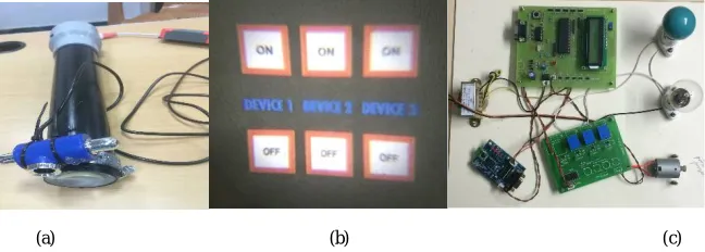
Fig. 7 Text Detection and In painting (a) Projector of Virtual Reality (b) Image projection of Virtual Reality (c) Receiver mechanism of Virtual Reality
When the virtual reality projector is ready to use, it projects the 2d image on any surface. The projected is image can be Viewed by the user from a greater distance. The image would be crystal clear. The user by default, interrupts the ray falling on the surface by hand movement in order to perform any kind of operation. The camera then captures the action made by the user. The GUI application recognizes the sudden interruption and there by insisting the ZigBee controller to transmit the signal ones a network. The ZigBee receiver placed on a far-away end, receiver the transmitted signal.The signal is then transmitted to a circuit board consisting of a step-down transformer, bridge rectifier, capacitor, voltage regulator, MAX 232 IC, relay circuit, reset switch and PIC microcontroller. In the circuit, the signal first passes through a step-down transformer. The step-down transformer is basically used to cut down power from 230v to the required 12v dc. After passing through the step-down transformer, the signal passes through a bridge rectifier which rectifies the voltage from 12v to 15 dc. The signal further passes through the capacitor, a change storage device, which filters the 5v dc. The voltage regulator then regulator the filtered voltage to a 3-volt dc. The reset switch is used to reset the board. The signal then passes through the MAX 232 IC which integrates the relay component to the microcontroller. The PIC microcontroller integrated with the relay component consists of an embedded c program to control the board. The signal then passes through the RELAY circuit which connects the 3v dc to 230v and ends to the other devices. The PN diode in RELAY circuit is used to avoid reverse bias in the circuit. Many devices can be accessed by connecting them to the RELAY circuit
IX. CONCLUSION
An operating a system manually would definitely consume the user’s energy and their time. In the previous system, we found that the systems were operated using remote control which does not exhibit transparency there by not providing an interactive experience. In our work, we have developed a system based on virtual reality. This is a novel concept of image accessing and functioning which gives us an interactive experiences
Introduction of 3D image processing to this system would like up the operating experience to a supreme level. Our system is a basic level implementation. Henceforth, implementing through 2D image is the only possibility
REFERENCES
[1] The official Bluetooth website from Bluetooth SIG: http://www.bluetooth.com
[2] Neng- Shiang Liang; Li-Chen Fu; Chao-Lin Wu. “An integrated, flexible, and Internet-based control architecture for home automation system in the internet era”. Proceedings ICRA `02. IEEE International Conference onRobotics and Automation, Vol. 2, pp.1101-1106, 2002.
[3] E. Yavuz, B. Hasan, I. Serkan and K. Duygu. “Safe and Secure PIC Based Remote Control Application for Intelligent Home”. International Journal of ComputerScience and Network Security, Vol. 7, No. 5, May 2007.
[4] B. Koyuncu. “PC remote control of appliances by using telephone lines”. IEEE Transaction on ConsumerElectronics, Vol. 41, Issue 1, pp.201-209, 1995.
[5] S. Schneider, J. Swanson and Peng-Yung Woo. “Remote telephone control system”. IEEE Transaction on ConsumerElectronics, Vol.43, Issue 2, pp.103-111, 1997.
[6] K.Tan, T.Lee and C.Yee Soh. “Internet-Based Monitoring of Distributed Control Systems-An Undergraduate Experiment”. IEEE Transaction on Education, Vol. 45, No. 2, May 2002.
[7] N. Swamy, O. Kuljaca and F. Lewis. “Internet-Based Educational Control Systems Lab Using Net-meeting”. IEEE Transaction on Education, Vol. 45, No. 2, pp.145- 151, May 2002.
[8] P. Lin and H. Broberg. “HVAC Applications”. IEEE Industry Applications Magazine, pp.49-54, January 2002.