Dynamic Vibration Analysis of Gear Box Casing
Using ANSYS Software
Ganesha.B
1, Dr. K N Umesh
2, G Raghavendra Setty
3, Santhosh Naik
4Associate Professor, Dept. of Mechanical Engineering, Ballari Institute of Technology & Management, Bellary, Karnataka, India. 1
Former Dean & Professor, Department of Mechanical Engineering, P E S College of Engineering, Mandya, Karnataka, India. 2
Assistant Professor, Dept. of Mechanical Engineering, Ballari Institute of Technology & Management, Bellary, Karnataka, India. 3
Jr. Manager, Central Maintenance Department, JSW Steel Ltd, Vijayanagar Works, Bellary, Karnataka. India. 4
ABSTRACT: This technical paper contains the application of ANSYS software and also FFT analyzer to determine natural frequency and mode shapes of industrial gearbox casing. In order to prevent the resonance of the gearbox casing it is necessary to find the natural frequency and mode shapes. From the result, this analysis can show the range of the frequency that is suitable for gearbox casing which can prevent maximum amplitude.
KEYWORDS: Gearbox casing, Natural frequency, Finite element analysis, Ansys, Mode shapes, FFT Analyzer.
I. INTRODUCTION
II. PROBLEM DEFINITION
A high vibration is observed in the Gear box running at 1100-1200 rpm. It was identified from vibration analysis spectrum (FFT analyzer) gearbox casing was operating dangerously close to resonance. Hence dynamic analysis was taken up on the gear box to identify the causes of high vibration. It was found that the natural frequency of the gear box casing was close to gear meshing frequency.
In order to eliminate this problem the gear box casing natural frequency/frequencies should be shifted away from the operating gear meshing frequency range by suitable modifications. Various trials were done and the most suitable and optimal solution is recommended.
III. VIBRATION LIMITS
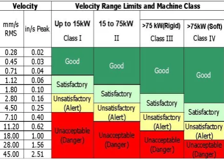
Machines were classified according to Vibration severity criteria standard ISO-10816-1.
Table 1: Classification of Machines and there vibration limits as per ISO Standard-10816-1
In order to determine the vibration amplitude in the gear box casing of mill house the vibration limits for the same has to be find based on the power rates shown in the table 1.Since the power rating of gear box drive is > 75 KW with rigid foundation to ground, so this gear box casing is coming under Class III and operating up to 4.5 mm/s beyond which increasing vibration level.
The design of the component should incorporate a methodology for dealing with factors causing unacceptable levels of vibration or to promote any scientific means of problem solving that would minimizing the harmful effects of resonance [7].
Directions of vibration measurement
There are three universal directions of vibration measurements, they are [1] Horizontal
Fig.1 Vibration spectrum of gearbox input horizontal direction
From the graph shown in fig 1 it is reveal that there is high vibration of 7.835 mm/s peak. Hence, gear box is running in unsatisfactory condition in horizontal direction requires monitoring [8] [9].
Fig.2 Vibration spectrum of gearbox input axial direction
From the graph shown in fig 3 it is reveal that there is vibration of 3.562 mm/sec peak. Hence, gear box is running in satisfactory condition in vertical direction.
From above three figures it is found that there is high vibration in horizontal and axial directions indicates high vibration level. It is found that gearbox casing running in resonance condition and in order to minimize this problem it is necessary to redesign/modify the existing gear box casing and check for dynamic analysis [10] [11].
IV. 3D CAD MODEL OF GEAR BOX CASING
FEM analysis is a powerful tool and its reliable results can be used for product performance. FEM based free vibration analysis of gearbox casing for noise and vibration reduction and vibration absorption of gearbox is plays a vital role. This work highlights on dynamic vibration response with fixed constraints. Noise and vibration of transmission system can be reduced by the structural optimization for better performance.
Solid Edge (V19) and Nastran (NX8) softwares are used for designing the gear box casing. The solid CAD model is shown in figure 4. The designed casing consisting of 14 holes at the both side of base used for constraining on ground.
Fig.4 3D model of Existing Gear Box Casing Fig.5 Meshed model of Existing Gear Box Casing
ANSYS 15.0 is FEA based analysis tool for structures. ANSYS 15.0 work on concept of nodes and elements. Elements are connected at a point known as node. This process is known as meshing. The fine meshing ensures more accurate results but increases calculation time. Fig 5 shows the meshed model of industrial gear box casing. The meshed model has 30749 nodes and16535elements.
The .iges file of casing is imported in Ansys 15.0 FEA based software used for free vibration analysis. The present study provides the strong base for optimizing the resonance problem of a casing by finding the mode shapes and natural frequencies of existing and modified casing [12]. Obtained first 10 natural frequencies and mode shapes of gearbox were considered.
Fig 6 shows the 3 dimensional model of modified gear box casing. Modification Details as follows
[1] 2 rods of diameter 120 mm & length 1900 mm with 2 nuts of diameter and side is 120 mm and thickness of the each nut is 100 mm fitted in two sides of the casing (attached near to the base).
[2] 2 rods of diameter 60 mm & length 1900 mm welded in two sides of the casing (attached near to the top). [3] 10 holes of diameter 50 mm made in supporting strips in top face of the casing.
[4] There are 4 different dimensions of the plates are welded in both sides of the casing body. The dimensions are (271x694) mm, (279x694) mm, (341x694) mm and (364x694) mm.
Fig 7 shows the meshed model of Modified industrial gear box casing. The meshed model has 42014 nodes and 20708 elements.
V. MATERIAL PROPERTIES AND BOUNDARY CONDITIONS
Grey Cast Iron FG200 a damping material has been selected as casing material. It was good on both criteria of vibration and manufacturing prospectus. The Mechanical properties Elastic modulus, Poisson ratio and density were required for free vibration analysis. The grey cast iron FG200 material properties are elastic modulus 1.4e11 Pa, Poisson ratio 0.26, density 7200 kg/m3 [13].
Gear box casing base is constrained on ground using connecting bolts. There are two types of predefined boundary conditions are available in Ansys for modal and free vibration analysis [14]. These are free-free and fixed-fixed boundary conditions. In free-free boundary conditions all degrees of freedom are unconstraint. Fixed-fixed boundary condition is suitable for the casing analysis since it is constraint on ground by bolts. To provide the fixed-fixed boundary condition we have fixed the base part of the casing in software environment.
In actual condition casing is tightly fixed on the ground using connecting bolts. Fixed-fixed constraint boundary condition is suitable for the gearbox casing analysis; it is constraint the motion of holes positions. First 10 natural frequencies and corresponding vibration modes were evaluated for two cases. Natural frequencies vary from 294.97 Hz to 316.76 Hz.
VI. DYNAMIC ANALYSIS OF EXISTING GEARBOX CASING
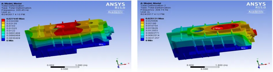
The FEM numerical simulation presents the first 10 mode shapes and corresponding natural frequencies for existing gear box casing shown in below figures from fig.8 to fig.17
Fig.10 3rd Frequency mode range at 228.18Hz Fig.11 4th Frequency mode range at 294.97Hz
Fig.12 5th Frequency mode range at 314.28Hz Fig.13 6th Frequency mode range at 361.43Hz
Fig.16 9th Frequency mode range at 489.61Hz Fig.17 10th Frequency mode range at 497.44Hz
VII. DYNAMIC ANALYSIS OF MODIFIED GEARBOX CASING
The FEM numerical simulation presents the first 10 mode shapes and corresponding natural frequencies for modified gear box casing shown in below figures from fig.18 to fig.27
Fig.22 5th Frequency mode range at 343.93 Hz Fig.23 6th Frequency mode range at 379.54 Hz
Fig.24 7th Frequency mode range at 387.88Hz Fig.25 8th Frequency mode range at 442.59Hz
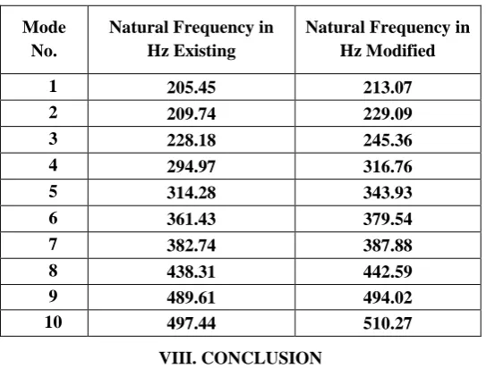
Table 2: Comparison of natural frequencies of existing and modified gearbox casing
Mode No.
Natural Frequency in Hz Existing
Natural Frequency in Hz Modified
1 205.45 213.07
2 209.74 229.09
3 228.18 245.36
4 294.97 316.76
5 314.28 343.93
6 361.43 379.54
7 382.74 387.88
8 438.31 442.59
9 489.61 494.02
10 497.44 510.27
VIII. CONCLUSION
The following solution is recommended, after the detailed dynamic analysis conducted on the gear box casing. Gearbox casing was operating dangerously close to resonance, so dynamic analysis was carried to shift the natural frequencies of the gear box casing. Different modification was tried and the best feasible modification is suggested to shift the natural frequencies of the gearbox casing. The gearbox casing natural frequency of 4th gear meshing frequency 294.97 Hz is shifted to 316.76 Hz by giving external stiffness. As a result of this modification the stiffness of the gear box casing is increased and the natural frequency is shifted away from the resonance band.
REFERENCES
[1] Bhavin Gajjar, Finite Element Analysis of Gearbox Housing, International Journal for Scientific Research and Development (IJSRD), Vol.02, ISSUE 03,2014, ISSN (online): 2321-0613.
[2] M.Davis, Y.S. Mohammed, A.A. Elmustafa, P.F. Martin, C. Ritinski, Designing for Static and Dynamic Loading of a Gear Reducer Housing with FEA. ISBN: 978-1-55589-962-2.
[3] Y. Shivraj Narayan, K. Karumanchi, Modeling and Core Cavity Preparation of Side Engine Cover of a Gear box Casing Using PRO/E Software. National Conference on Advances in Mechanical Engineering (NCAME)-2010, 18th December 2010.
[4] SOLIDEDGE Version 19.0 (2006)
[5] ANSYS R15.0 Academic, Dynamic & Structural Analysis guide (2016)
[6] V. B. Maner, M.M. Mirza, ShrikantPawar, Design Analysis And Optimization For Foot Casing Of Gear-Box. Proceedings of 3rd IRF International Conference, 10th May-2014, Goa, India, ISBN: 978-93-84209-15-5.
[7] D. Bently, Bently Nevada Co. Predictive maintenance through the monitoring and diagnostics of rolling element bearings, Applications Note ANO44 (1989) 2-8. [8] Jiri Tuma , “ Gearbox Noise and Vibration Prediction and Control” ,International Journal of Acoustics and Vibration Vol. 14, pp 1-11, 2009.
[9] P.D. McFadden, "Condition monitoring of rolling element bearings by vibration analysis". Proceedings of the I.MECH.E. Machine Condition Monitoring Seminar, January 9th, 1990, pp 49-53.
[10] N. Sawalhi, R.B. Randall, Gear Parameter Identification In Wind Turbines Using Diagnostic Analysis Of Gear-Box Vibration Signals. Springer – Verlag Berlin Heidelberg 2014.
[11] P. Czech, “Diagnosis of industrial gearboxes Condition by vibration and time-frequency, Scale-frequency, frequency-frequency analysis” Metalurgija, Vol. 51 pp. 521-524, 2012.
[12] P. Czech, “Diagnosis of industrial gearboxes Condition by vibration and time-frequency, Scale-frequency, frequency-frequency analysis” Metalurgija, Vol. 51 pp. 521-524, 2012.