Dual Function Refrigeration System
Dr. Ajoy Kumar
Principal, Chhatrapati Shivaji Maharaj Institute of Technology, Panvel, University of Mumbai, India
ABSTRACT
:
This paper describes the design, construction, and testing of an integrated heat recovery system which has been designed to enhance the performance of a residential refrigerator as a waste heat recovery unit as well as itsnormal purpose of cooling. As a necessary modification, the condenser tube located at the back side of normal
refrigerator has been removed and relocated in the hot case being wrapped around it. In this way a new path to refrigerant flow from compressor to expansion device via tube of the hot case, is given .The refrigerator was housed in a controlled-environment chamber, and it was instrumented so that its performance could be monitored carefully. The system has been tested under a variety of hot air usage protocols and the resulting data set has provided significant
insight into issues associated with commercial implementation of the concept.C.O.P of the hot case system located on
the top considerably increases by almost one unit without much change in the original design and without affecting the
input energy as well.The temperature achieved by the hot case is about 56°C.
KEYWORDS: Refrigerator , Hot case ,Refrigerating effect ,C.O.P
.
I. INTRODUCTION
Refrigeration is the action of cooling and in practice this requires the removal of heat and rejecting it at a higher temperature from within a given space for the purpose of chilling foodstuffs, preserving certain substances ,storing perishable foodstuffs, furs, pharmaceuticals, or other items that require cold storage [1].The principle of the Vapor Compression system employed requires evaporation and condensation to occur when liquid refrigerant is receiving and rejecting the specific enthalpy of vaporization and the specific enthalpy of condensation respectively. These processes are at constant temperature and pressure respectively [2]. Almost all refrigeration systems in the world today employ the vapor compression system. Wolf [3] in 1913 patented a Refrigeration Apparatus that was the first attempt at domesticating the vapor compression system. His work consisted a Motor and Compressor combination that worked both as a pressure pump and as a pressure relief valve to transfer refrigerant. He used Sulphur IV oxide as refrigerant. Betchold and Mellowes [4] in 1915 patented a Cooling Apparatus whose elements were encased in a singular unit as is the case in modern refrigerators. They used a liquid condenser and employed Sulphur IV oxide as a refrigerant. Carrier [5] in 1913 patented a system for maintaining the humidity and air quality inside a factory by the use of atomizing sprays, steam injectors, and fan ducts. Ledbetter [6] in 1989 patented an Air Conditioning Refrigerator. His work consisted of a freezer that could also work as an air conditioner. It consisted of two vapor compression systems which were both kept indoors and his condenser was water cooled in nature. A machine that possess two vapor compression systems is hardly energy efficient and a water cooled condenser is not feasible in a place where water is scarce. The work of Wei et al [7] concluded that correlation used in obtaining heat transfer coefficients used for condenser design proposed by Akers e t a l, showed acceptable predictions for mass fluxes employed in domestic systems.
While we begin our journey in new millennium with several hopes and challenges, it is very timely to utilize the wastage heat for the benefit of mankind and to meet the increasing demands of energy for mankind .The objective should be to extract, convert, transform, transport, distribute and reconvert different types of energy with least pollution and with highest economy. So a process and its analysis are involved regarding transformation of energy into exergy (useful energy) and energy (worthless energy).
In normal operation cycle of refrigerator, condenser tubes loose heat to atmosphere by natural convection method and it is considered as wastage heat.
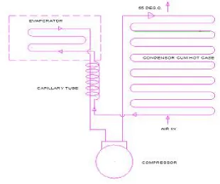
The objective of the device is to utilize this wastage heat energy. For this purpose a thermal storage device named as hot case has been employed to recover the wastage heat. As a necessary modification, the condenser tube located at the back side of normal refrigerator has been removed and relocated in the hot case being wrapped around it. In this way a new path to refrigerant flow from compressor to expansion device via tube of the hot case, is given .While passing through this tube of hot case refrigerant looses heat and increases the temperature of hot case. The temperature achieved by the hot case is about 56°C.
This temperature of hot case can be used for keeping the food (tea, coffee, sliced bread, samosa etc) warm. Thus from refrigerator with hot case, two totally opposite phenomenon i.e. cooling and heating in one device are fulfilled ,which is very much useful to domestic houses and restaurant in particular.
II. WORKING OF REFRIGERATOR WITH THE HOT CASE
A refrigeration process indicates the change of thermodynamic properties of the refrigerant and the energy transfer between the refrigerant and the surroundings. In normal refrigerator, the refrigerant vapor coming out from evaporator or freezer box is compressed by the compressor to high pressure and temperature than that of atmospheric values so that after heat rejection from the condenser into atmosphere, it gets condensed as shown in Fig.1.
Fig. 1 .Working Cycle Diagram
Fig. 2. Cycle Analysis
Here after compression, the refrigerant while passing through condenser coil rejects heat to atmosphere. Since this condenser coil is relocated around an aluminum box the heat transfer takes place from hot refrigerant passing through the condenser to the box by means of conduction process. Therefore temperature of aluminum box increases. This aluminum box has been placed inside the hot case with proper insulation of glass wool and thermocol. Here the refrigerant loses heat, not to the atmosphere but is stored in hot case for better utilization. Rest of the working of the refrigerator is same.
III. HOT CASE DESIGN AND CONSTRUCTION
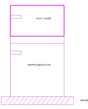
Fig. 3. Refrigerator with Hot Case
Hot case is basically a thermal storage device. Thermal storage device is used to store energy which is basically of two types as given below:
a) Sensible heat storage b) Latent heat storage
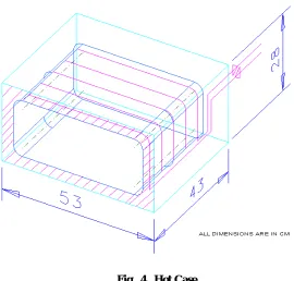
There is a change in phase during condensation of the vapor refrigerant in hot case; it is of sensible heat storage device. The heat is rejected to the air present inside the hot case (Fig. 4). It consists of following
:
Aluminum box
Copper box
Thermocol
Glass wool
Outer box made of color-coated steel
Handle, cock, hinges etc.
Fig. 4 . Hot Case
Approximately same condenser heat transfer area removed from the back side has been considered as a new heat transfer area inside the hot case.
Total length of condenser coil = 866 cm
Total length of the condenser coil wrapped on an aluminum box inside the hot case =872cm. The aluminum box is the hot compartment of the hot case having dimension = 40 x 30 x 18 cm. The hot case located over the top of the refrigerator has dimension as 53 x 43 x 28 cm.
A lock with magnetic rubber (gasket) has been provided to the door of the refrigerator for having perfect insulation.
IV. OBSERVATION TABLE FOR DOMESTIC REFRIGERATOR
Initial temperature of water (Ta): 29°C
Table 1:
C.O.P of domestic refrigerator of 165 L capacity without any modificationTime S.N. Te
(°C) Pe (Psi) Tc (°C) Pc (Psi) Enthalpies (KJ/kg) C.O.P
h1 h2 h3
10.00 1 1.1 40 48 125 149 218 80 3.75
11.00 2 -3.8 40 51 125 190 220 80 3.66
12.00 3 -3.9 40 50 125 190 219 80 3.79
13.00 4 -3.8 40 50.5 125 190 219 80 3.79
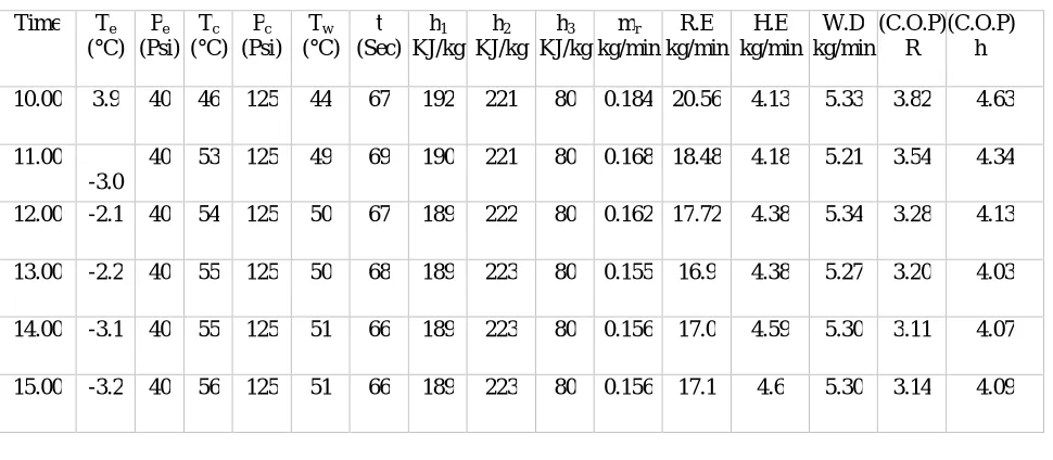
Table 2:
C.O.P. of modified system of domestic refrigerator of 165 L capacityTime Te (°C) Pe (Psi) Tc (°C) Pc (Psi) Tw (°C) t (Sec) h1 KJ/kg h2 KJ/kg h3 KJ/kg mr kg/min R.E kg/min H.E kg/min W.D kg/min (C.O.P) R (C.O.P) h
10.00 3.9 40 46 125 44 67 192 221 80 0.184 20.56 4.13 5.33 3.82 4.63
11.00 -3.0
40 53 125 49 69 190 221 80 0.168 18.48 4.18 5.21 3.54 4.34
12.00 -2.1 40 54 125 50 67 189 222 80 0.162 17.72 4.38 5.34 3.28 4.13
13.00 -2.2 40 55 125 50 68 189 223 80 0.155 16.9 4.38 5.27 3.20 4.03
14.00 -3.1 40 55 125 51 66 189 223 80 0.156 17.0 4.59 5.30 3.11 4.07
15.00 -3.2 40 56 125 51 66 189 223 80 0.156 17.1 4.6 5.30 3.14 4.09
Te Temperature of refrigerant leaving evaporator Pe Pressure of refrigerant leaving evaporator Tc Temperature of refrigerant entering condenser Pc Pressure of refrigerant entering condenser
k Energy meter constant
h1 Enthalpy of refrigerant entering compressor h2 Enthalpy of refrigerant leaving compressor h3 Enthalpy of refrigerant entering the capillary tube h4 Enthalpy of refrigerant entering evaporator mw Mass of water kept in hot case to be warmed mr Mass flow rate of refrigerant
(C.O.P.)R C.O.P. of refrigerator alone
(C.O.P.)h C.O.P. of refrigerator considering hot case Cpw Specific heat of water
Taking the observation set from first row of the Table. 2.
mr = W.D/((h2-h1)x60) Kg / min = 1/t x n/(k x 3600 ) x1/{(221-192) x 60} =0.184 Kg / min
Refrigerating effect (R.E.) = mr(h1-h4) = 0.184(192-80) = 20.60 KJ/min Heating effect (H.E.) = mwCpw(Tw-Ta) = 3X4.187X (44-29)/60 = 3.14 KJ/min Work done (W.D.) = mr(h1-h2) = 0.184(221-192) = 5.33 KJ/ min
(C.O.P)R = R.E./W.D. = 3.82 (C.O.P)h = (R.E.+H.E.)/W.D. = 4.59
V. EXPERIMENTAL RESULTS
1. C.O.P. of a domestic refrigerator is found to be 3.74 which remain almost constant 2. C.O.P. of modified system considering only refrigerating effect = 3.5
3. C.O.P. of the same modified system considering heating effect as well = 4.35 4. R.E. = 17.96 KJ/min
5. H.E. = 4.21 KJ/min
VI. CONCLUSION
A method to recover and utilize waste heat, in refrigerators is studied. The presented project, attempted to recover the waste heat from a 165 L refrigerator, for domestic purposes. The upper chamber of the refrigerator was developed as a hot chamber, by extension of the condenser coils, and the attachment of the upper portion, towards the top surface of the lower chamber of the refrigerator. The temperature variation in the hot chamber and the cold chamber is studied considering the various parameters like time, capacity of chamber and load. From the results obtained, it is concluded that the temperature in the hot chamber increases and that in the cold chamber decreases with increase in time. As the atmospheric temperature increases, since the loss of heat from the hot chamber to the atmosphere decreases, the maximum temperature within the hot chamber increases. The variation in capacity of hot chamber was obtained by employing the use of thermocol, and from the obtained observations, we understand that the temperature within the hot chamber increases, with decrease in cubic capacity. The time taken for the hot chamber to attain any particular temperature, without load, was lesser than with load in the hot chamber. The COP calculated, may be higher than the actual value, because of leakage of heat whilst the door is opened or closed, the age of the refrigerator, and the physical condition of the gasket. From the results, it has been established that the above mentioned method of heat recovery, can be designed and developed for every household refrigerators, with the minimal cost. Hence the reuse of waste heat paved way for maximum energy conservation. This work can be enhanced by providing better insulation which in turn minimizes the heat loss and increases the efficiency of the system.
C.O.P of the hot case system considerably increases without much change in the original design and without affecting the input energy as well.
VII. APPLICATION
The following are some of the applications of the heat recovery system: 1. Space heating.
2. Industrial drying.
3. Maintaining temperature of substances up to 50 0C. 4. Keep snacks and food warm.
5. Used in health care centers, school etc. 6. To wash the cans in dairy by hot condensate. 7. To dry clothes, grains etc.
8. Any other application requiring warm air.
REFERENCES
1. Hundy, G. F., Trott, A.R. and Welch, T. C. “Refrigeration and Air Conditioning”, Butterworth Heinenmann, Amsterdam, 2008. 2. Oddiah, P.A., “Refrigeration “. GET 222: SWEP, University of Ilorin, 1997/1998 Session.
3. Wolf, W.F., “Refrigerating Apparatus”. US Patent: US 1,126,605 1913. 4. Bechtold and Mellowes, “Cooling Apparatus”. US Patent: US 1,276,612A. 1915.
5. Carrier, W.H., “Method of Humidifying Air and controlling the humidity and temperature there of”. US Patent: US 1,085,971A. 1913. 6. Ledbetter, R. G. “Air Conditioning Refrigerator”. US Patent: US 4,821,530. 1989,
7. Wei, W, Fang, X. and Shi, R, “A Comparative Study of Heat Transfer Coefficients for Film Condensation”, Energy Science and Technology, Vol. 3 (1) 1 – 9 , 2012.
8. Reay, D.A. “Low Temperature Waste Heat Recovery in the Process Industry”. Good Practice Guide No. 141. 1996:35-36.
9. Clark, Robert A, Smith, Richard N.; Jensen, Michael K. “An experimental study of waste heat recovery from a residential refrigerator” Energy Conversion Engineering Conference Volume: 3, 1996: 1887 – 1892.
10. I. W. Eames, S. Aphornratana. "The Jet-Pump Cycle-A Low Cost Refrigerator Option Powered By Waste Heat”, Heat Recovery Systems and CHP November 1995, 15 (8): 711-721.
11. Wu Zhijiang , Wang Nan; Zhu Gongsheng. “Application Research of Evaporative Cooling in the Waste Heat Recovery”, Digital Manufacturing and Automation (ICDMA), International Conference on, 18-20 Dec. 2010: 275 – 277.