Transactions of the 17th International Conference on
Structural Mechanics in Reactor Technology (SMiRT 17)
Prague, Czech Republic, August 17 –22, 2003
Paper # C02-6
Modeling of the Cold Work Stress Relieved Zircaloy-4 Cladding Tubes
Mechanical Behavior under PWR Operating Conditions
Fabrice Richard1), Patrick Delobelle1), Sylvain Leclercq2), Pol Bouffioux2), Gilles Rousselier2)
1) Laboratoire de Mécanique Appliquée, Besançon, France
2) EDF R&D, Département MMC, Les Renardières, Ecuelles, France
ABSTRACT
This paper proposes a damaged viscoplastic model to simulate, for different isotherms (320, 350, 380, 400 and 420°C), the out-of-flux anisotropic mechanical behavior of cold work stress relieved Zircaloy-4 cladding tubes over the fluence range 0-85.1024 nm-2 (E>1MeV). The model, identified from uni and biaxial tests conducted at 350 and 400°C,
is validated from tests performed at 320, 380 and 420°C. This model is able to simulate strain hardening under internal pressure followed by a stress relaxation period (thermal creep), which is representative of a pellet cladding mechanical interaction occurring during a power transient (class 2 incidental condition). Both the integration of a scalar state variable, characterizing the damage caused by a bombardment with neutrons, and the modification of the static recovery law allowed us to simulate the fast neutron flux effect (irradiation creep).
KEY WORDS: constitutive equations, Zircaloy-4, cladding tubes, viscoplasticity, creep, hardening, relaxation, irradiation, temperature effect, anisotropy, PCMI.
INTRODUCTION
Today, more than 70 percent of French electric power has a nuclear origin, generated by 58 pressurized water reactor (PWR). The research conducted by Electricité de France and dedicated to the fuel assembly life extension and the production adaptability to the network demand brings about more severe mechanical loadings of the cladding. To prevent the risk of failure of a cladding tube without excessive conservatism, it became consequently necessary to simulate the anisotropic mechanical behavior of Zircaloy-4 with non-linear models predicting realistic fields of stress and strain for all cases. Such a model should also be able to take into account the irradiation effects upon the mechanical behaviour at cladding operating temperatures (ranging from 320°C to 420°C), fluences (which may reach 100.1024 nm-2, E>1MeV), and fast neutron flux.
An anisotropic viscoplastic model at 350°C was developed during a first phase from multiaxial tests conducted on Zircaloy-4 tubes [1]. In a second phase, the model has been expanded to describe the effect of variable temperatures (between 350 and 400°C),) before taking into account irradiation effect out-of-flux from non irradiated state to high fluence (0 to 85 1024 nm-2, E>1MeV) [2]. This paper presents the last phase of the project during which the model has
been improved to describe the effects of long term creep, a larger temperature range (from 320°C to 420°C) and fast neutron flux (irradiation creep).
MODELLING OF THE NON IRRADIATED MATERIAL
Isotherm (T=350°C)
The equations of the model are given in Table 1. The different parameters of the equations are initially constant and therefore do not depend on temperature, irradiation state and neutron flux.
In the case of small strains, the total strain [ε] can be split up into two terms: an elastic strain [εe], assumed to be isotropic and a viscoplastic strain [εvp], which is anisotropic.
Three kinematical variables are necessary to simulate the strong non-linearity of the stress-strain curves. The mechanical behavior is completely defined by the evolution laws of the kinematical hardening variables [X′], [X′(1)] and [X′(2)]. The first term of these equations is the linear part of the hardening, the second term represents the dynamic recovery and the last one represents the time-dependent static recovery.
Table 1. Equations of the model. Voigt matrix notations:1≡r,2≡θ,3≡z
[
1 1 2 22 3 33 4 23 5 13 6 12]
T , , , , ,
]
[σ = σ =σ σ =σ σ =σ σ =σ σ =σ σ =σ
[
1 11 2 22 3 33 4 23 5 13 6 12]
T , , , 2 , 2 , 2
]
2 Constitutive equations (with classical notations)
] [ ] [ ]
[ε& = ε&e + ε&vp
] ][ [ ] [ ] [ 1 ]
[ε& σ& ∆T σ& ∆ E
E
e = +ν −ν
X vp vp − ′ − ′ = σ ε [ ][ ] 2 3 ]
[ε& & M σ X
n vp N X σ ε − =ε&0 sinh
&
2 1
T[ ][ ]
] [ 2 3 ′− ′ ′− ′ =
−X σ X M σ X
σ ] ][ [ ] [ 3 1 ] [ ]
[σ′ = σ − ∆ T σ ∆ , [ ] [ ][ ]
3 1 ] [ ]
[X′ = X − ∆ T X ∆ with [∆]T =
[
1,1,1,0,0,0]
Equations of the three kinematical hardening variables :
X X X r ε Y p m m vp
vp] [ ]([ ] [ ]) sinh [ ][ ]
][ [ 3 2 ] [ 0 0 ) 1 ( 0 X R X X Q ε N X ′ − − ′ − ′ =
′ & &
& − ′ − ′ =
′ p Y &vp ε&vp
& [ ][ ] [ ]([ ] [ ])
3 2 ]
[ (1) (2)
0 1 ) 1
( N ε Q X X
X − ′ =
′ p Y vp ε&vp
&
& [ ][ ] [ ][ ]
3 2 ]
[ (2)
0 2 ) 2
( N ε Q X
X
[
0,0,0,0,0,0]
] [ T (0) ) ( = ′i X 2 1 T[ ][ ]
] [ 2 3 ′ ′
= X R X
X
Anisotropy is introduced in the model through the four fourth order tensors affecting the flow direction [M], the linear part of the kinematical hardening [N], and the dynamic and static recovery, [Q] and [R], of these hardening variables, respectively. The symmetry of the crystallographic texture in the tubing reference system (r,θ,z) induces orthotropic properties, which explains the form of the anisotropy matrix : the matrices [M] [N], [Q], and [R] have an orthotropic symmetry. For example, for [M]:
[ ]
= 66 55 44 33 23 13 23 22 12 13 12 11 0 0 0 0 0 0 0 0 0 0 0 0 0 0 0 0 0 0 0 0 0 0 0 0 M M M M M M M M M M M M M (1)The relations of incompressibility lead to :
0 33 23 13 23 22 12 13 12
11+M +M =M +M +M =M +M +M =
M (2)
0 1 2 3 4 0
100 200 300 400 500 600
εz(
σz(MPa)
2 10-1 %
2 10-2 %
2 10-3 %
2 10-4 %
0 1 2 3 4
0 100 200 300 400 500 600
εθ(%
σθ(MPa)
0.71 0.468 0.233 0 -0.243 -0.471
a) b)
Fig. 1 a) Longitudinal tensile tests performed at 350°C for different strain rates ε&z b) Biaxial tensile tests at %/s
10 . 2 −2
=
θ
4
0 20 40 60 80 100 12
0 0.5 1 1.5 2 2.5
εvp z (%)
40 38 35 27
0 100 200 300 400
0 0.2 0.4 0.6 0.8 1
1.2 εvpθ (%)
275 200 170 140 100
a) b)
0 2000 4000 6000 8000 10000 12000 14000 0
0.5 1 1.5 2 2.5 3 3.5 4
t (h εvp
θ (%)
180 MPa 150 MPa 120 MPa 80 MPa
0 0.2 0.4 0.6 0.8 1
0 100 200 300 400 500 600
t (h)
σθ(MPa) 2 10-2 %/s
2 10-3 %/s
a) b)
Fig. 3 a) Long term biaxial creep tests (α = 0.5) performed at 350°C for different stress σθ b) Biaxial relaxation tests (α = 0.5) performed at 350°C for different strain rates ε&θ. Experimental results and simulations.
The model is in good agreement with the results of the tensile and creep tests (Fig 1a and 2a), of the biaxial tests at different biaxiality ratio α (Fig 1b), and of the biaxial creep tests with α = 0.5 and different stress levels (Fig 2b-3a). At this stage of the model development and of its identification on non irradiated claddings, the formulation is validated by comparing the model predictions and the tensile tests performed under internal pressure and followed by a relaxation phase (Fig 3b). These tests simulate a pellet-cladding mechanical interaction type loading. The results can be considered satisfactory.
Temperature effect
Only the parameters E, N, ε&0, X0, rm, Y0 and R22 have been considered as temperature-dependent:
T E E T
E( )= 0− 1
T N N T
N( )=− 0+ 1
n
T N kT H A
T) exp( / )[ ( )]
( 0
0 = ε −∆
ε& &
) exp( )
( 0
0 T A sT
X = X −
0 )] ( )[ / exp( )
( r 0 m
m T A H kT X T
r = m −∆ ∗
T Y Y T
Y0( )= 1− 2
{
2}
3 2 1
2 23
22(T)=(3/2)R +η exp−0.5[(T−η )/η ] R
(3)
Let us emphasize that the anisotropy matrix [R] depends on the temperature through the coefficient R22. k is the Boltzmann constant, ∆H and ∆H∗ the apparent creep activation energies.
6
between the calculation results and the experimental tests performed at 380°C and 420°C (Fig 7) as well as the use of the pellet-cladding mechanical interaction type loading (hardening-relaxation test - Fig 6b).
0 1 2 3 4
0 100 200 300 400 500
εz(%
σz(MPa)
2 10-1 %/
2 10-2 %/
2 10-3 %/
0 0.5 1 1.5 2 2.5
0 100 200 300 400 500
εθ(%)
σθ(MPa) 2 10-2 %/s
2 10-3 %/s
a) b)
0 100 200 300 400 500 0
0.5 1 1.5 2
t (
εvpz (%) 200 M
175 M 140 M
0 50 100 150 200 250 300 350 400 4
0 0.5 1 1.5 2 2.5 3 3.5 4
t (h)
εvpθ (%) 200 MPa
170 MPa 140 MPa 100 MPa
a) b)
Fig. 5 Longitudinal an biaxial creep tests performed at 400°C for different stress: a) σz and b) σθ =2σz.
8
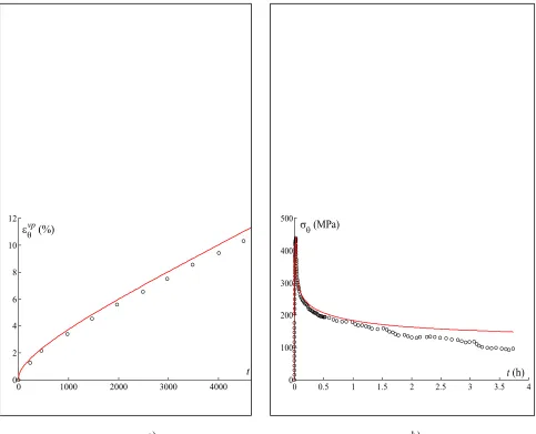
0 1000 2000 3000 4000
0 2 4 6 8 10 12
t
εvp
θ (%)
0 0.5 1 1.5 2 2.5 3 3.5 4
0 100 200 300 400 500
t (h) σθ(MPa)
a) b)
0 500 1000 1500 2000 2500 3000 35 0 0.5 1 1.5 2 2.5 3 3.5 4 εvp
θ (%) 11
9
0 100 200 300 400
0 0.5 1 1.5 2 2.5
t (h
εvp
θ (%) 420°C400°C
350°C
a) b)
Fig.7Predictive character of the model at 380 C and 420°C : a) Biaxial creep tests performed at 380°C for different stress σθ . b) Biaxial creep tests performed at σθ−σr =100MPa for different temperatures.
Experimental results and simulations (α = 0.5)
MODELING OF THE IRRADIATION EFFECT (OUT-OF-FLUX)
The irradiation state induces a marked hardening as well as a decrease of the creep rate (Fig 8). These effects are particularly apparent during two operating cycles in PWR (~45.1024 nm-2, E>1 MeV) and become less perceptible for
higher values of the fluence φ. To take into account the saturation observed in the evolution of the mechanical properties, we use an isotropic damage variable D such as:
{
1 exp[ ( ) ]}
)
( 1
0 ∗ − − ∗ φ
=D T D T
D (4)
where T∗is the irradiation temperature which may be different from the temperature T of the test. In this part of the study, T∗ is nearly constant (~335°C). A possible anisotropy of the damage might be easily integrated into the model by introducing a second order tensor [A] such that [D]=[A]D.
The experimental results show that the static recovery of the material during creep tests is a decreasing function of the fluence. According to this result, we propose to rewrite the evolution law of the kinematic strain hardening variable
]
[X′ by assuming the parameters X0 and rm of the static recovery term to depend on the irradiation damage. To take into account the strain-rate dependent stress evolution with irradiation, the parameters ε&0,
l l ∆ − = ε and []
( ) ( )( ) ( ) ( )( ) ( ) ( ) ( ) ( ) ( )( ) ( ) ( )( ) ( ) ( ) ( ) ( ) ( ) ( ) ( ) ( ) ( ) ( )( ) ( ) ( ) = ∑ ∑ ∑∑∑ ∑∑∑ ∑ jjjj jjjjj jjjj jjjjj jjjj jjjj jjjj jjjj jjj xA E y x A E x A E y x A E y A E y A E xA E y A E A E 2 2
C also depend on
10
0 0.5 1 1.5 2 2.5
0 100 200 300 400 500 600 700 800
εθ(%)
σθ(MPa)
45 1024 n/m2 5.1 1024 n/m2 0
0 10 20 30
0 0.5 1 1.5 2 2.5 3 3.5 4
t
εvp
θ (%) 4.4 10
24 n/m
20.8 1024 n 45 1024 n/m 80 1024 n/m
a) b)
Fig. 8 a) Biaxial tensile test performed ε&θ =2.10−2 %/s and 350°C on post-irradiated tubes b) Biaxial creep tests performed at σθ =410MPaand 350°C for different fluences. Experimental results and simulations (α = 0.5)
Let us recall that the five parameters N, ε&0, X0, rm and Y0, which depend on damage, also depend on the temperature. The evolution equations of these parameters are strongly non-linear, like the phenomena to be modeled :
)] exp( 1 [ )
,
(T D N0 N1T D
N =− + +µ − −τ
) exp( )] , ( )[ / exp( )
,
( 0
0 ε χ γ
ε& T D = A& −∆H kT N T D n − D
) exp( ) exp( )
,
( 0
0 T D A sT ηDβ
X = X − −
) exp( )] , ( )[ / exp( )
,
( 0
0 m w
r
m T D A H kT X T D D
r = m −∆ ∗ −ξ
] exp( 1 [ )
,
( 1 2 1 2
0 T D Y Y T g g D
Y = − + − −
(5)
The model parameters linked to irradiation through the variable D, as well as those which control the kinetics of
D, are identified numerically on biaxial tensile and creep tests made at 350°C.
MODELING OF THE NEUTRON FLUX EFFECT
In order to incorporate irradiation creep due to fast neutron flux in the model and according to equation (4), the damage evolution with respect to fast neutron flux is written as follows :
φ&
& D1(T )[D0(T ) D]
whereφ& is the neutron flux and T∗ the irradiation temperature. Fig 9a shows that the saturation of the damage D0
depends on the irradiation temperature.
D0 and D1 are identified at T∗=335°C (irradiation temperature of the material for the post irradiated
experimental tests – T* corresponds to the mean temperature of the fuel rod during base operating conditions). During a test under fast neutron flux, the irradiation temperature is equal to the temperature of the test. The temperatures under study are in the range of the significant hardening decrease (Fig 9a). Thus, according to Fig 9a, we propose a linear evolution of the saturation of the damage with the irradiation temperature, allowing the cancellation of the damage effects for temperatures above ~380°C:
cste D T D A T A T
D ∗ = − Dp ∗+ D ∗ = =
1 1
0( ) 1 , ( ) (7)
0 5 10 15 20 25 30 35 40 45
0 100 200 300 400
% YS
ZR2 (Howe) fluence = 9.5 10e23 nm ZR4 fluence = 4.5 10e23 nm-2 ZR4 (Baroch) fluence = 10e25 ZR4 (Baroch) fluence = 10e25
nm-EDF fluence = 8 10e25 nm-2
-18 -17 -16 -15 -14
4.0 4.2 4.4 4.6 4.8 5.0 5.2
under flux 2500-4000h
out-of-flux 2500h
[
(%/s)]
ln vp
θ
ε&
(
)
[
MPa]
lnσθ−σr
a) b)
Fig. 9 a) Yield Stress versus irradiation temperature during tensile test performed on post-irradiated material b) Evolution of the steady creep rates versus stress at 380°C.
12
-19.5 -17.5 -15.5
1.40E-03 1.50E-03 1.60E-03 1.70E-03
1/T (K-1) under flux (3000h)
out-of-flux (2500-3000h)
[
(%/s)]
ln vp
θ
ε&
-19 -18 -17 -16 -15
4 4.5 5 5.5
out- of-flux 5000h under flux 3000h
[
(%/s)]
ln vp
θ
ε&
(
)
[
MPa]
lnσθ−σr
out- of-flux 2000h
a) b)
Fig. 10 Fast neutron flux effect (φ&≈2.1014n/cm2/s, α = 0.5) on the steady creep rates versus a) temperature b) stress (350°C)
To take these observations into account, we propose to rewrite the evolution of the static recovery equation :
[
( , )]
[
exp( )exp( / )) ( , )]
) , , ,
( 0
0 ξ φ
φ& ∗ ∗ &
∗ = X T D A − D −∆H kT +r T
T D T
rm m rm w irr (8)
with
) / exp( )
,
(T∗ =A − ∆H kT∗
rirr rirr irr
κ
φ
φ& & (9)
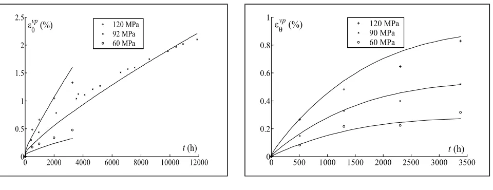
The tests used for the identification of the effects of the temperature correspond to all the available tests under the neutron flux φ&≈2.1014n/cm2/s. Fig 11 shows the ability of the model to simulate biaxial irradiation creep.
0 2000 4000 6000 8000 10000 12000 0
0.5 1 1.5 2 2.5
t (h)
εvpθ (%) 120 MPa 92 MPa 60 MPa
0 500 1000 1500 2000 2500 3000 3500 0
0.2 0.4 0.6 0.8 1
t (h)
εvpθ (%) 120 MPa 90 MPa 60 MPa
a) b)
Fig. 11 Biaxial creep tests (α = 0.5) under fast neutron flux φ&≈2.1014n/cm2/s. a) 350°C b) 320°C. Experimental results and simulations.
CONCLUSION
In order to include irradiation creep due to fast neutron flux, the damage variable is integrated and the static recovery term is modified to simulate a larger static recovery.
Future work to be done on this model will lead to incorporate irradiation creep due to fast neutron flux directly in the kinetic law of the damage, using a static recovery term.
REFERENCES
[1] Delobelle P., Robinet P. and Geyer P., “A model to describe the anisotropic viscoplastic behaviour of Zircaloy-4 tubes”, J. Nucl. Mater., 238 (1996), pp. 135-162.
[2] Schäffler I., Geyer P., Bouffioux P. and Delobelle P., “Thermomechanical behaviour and modelling between 350°C and 400°C of Zircaloy-4 cladding tubes from an unirradiated state to high fluence”, J. Eng. Mater. And Techn., 122