Study on Load Sensing Method by Speed of
PMSM
Donghoon Ban1, Sungho Jin1, Changhee Yoo2, Seongwook Ju2
Convergence Research Center for Future Automotive, DGIST, Korea1 R&D Center, Sangsin Brake Co. Ltd, Korea 2
ABSTRACT:The PMSM is widely used in industry. In order to detect faults and to monitor the system, it is important to detect changes in load for systems in which the PMSM is installed.However, the price of sensors is high and it is difficult to install sensors because of space limitations. Therefore, a method is proposed to detect the load using the speed of the motor in a system without sensors. An FOC method for operating the motor and a detection method using speed fluctuation have been studied; however, the speed includes many error components such as motor inertia and measurement error. To improve the accuracy of the speed measurement, the pulse count method has been studied and implemented. Actual experiments were performed to verify the proposed algorithm. The proposed algorithm detects the load variation at approximately the same time as the actual load is applied.
KEYWORDS:PMSM, FOC, inverter, speed, motor.
I. INTRODUCTION
A PMSM (Permanent Magnet Synchronous Motor) is often used to operate a mechanical system or actuator. Generally, position sensors such as encoders and hall sensors, speed sensors, or current sensors are used to drive the PMSM. A load cell is installed in the system to measure the torque generated by the motor or the torque acting on the motor. When faults occur in the system, or when an external force is applied to the system, or when an actuator is hit or removed from an object during operation, the torque that is required for the system varies. So, for accuracy control, it is necessary to detect that point accurately. Therefore, it is necessary to decide when to change the control method by measuring the torque acting on the system using the load cell.It is difficult to measure the load acting on the motor when the system is moving; this difficulty is compounded because a load cell cannot be installed in the system due to space constraints. Therefore, various methods of measuring the load acting on the motor have been studied.
II. RELATED WORK
In this paper, the speed is used to detect the point at which the load is applied. When a constant current flows through the motor, the motor rotates at its highest speed under no-load conditions. When a load is detected, the speed drops. Therefore, if the decelerating point can be accurately detected, it will be possible to accurately grasp the time at which the load acts.
III.FOCMETHOD
The common method for driving PMSM is 6 step control. However, since such control is performed six times per rotation of the motor, the driving efficiency of the motor is low, and noise such as vibration is generated. FOC is used to solve this problem. A block diagram of the FOC method is presented in Fig. 1. The FOC method is used due to its two advantages of smooth and efficient operation with fast dynamic response at both low and high speeds. When the PMSM rotates, a back-electromotive force is generated. The current of the generated back-electromagnetic force is measured using phase current sensors. Using the CLARK transformation, the current measured at three phases of the motor is converted to two-phase stationary coordinates. Using the rotor position and the PARK transformation, the converted 2-phase stationary coordinates are converted to 2-phass rotational coordinates. Thus, the 3-phase AC component is converted to a 2-phase DC component. And, PI control of the d and q axes is performed using the 2-phase DC component. The d-axis represents the magnetic flux component, and the q-axis represents the torque component. The d and q axis voltages resulting from PI control are converted to 3-phase voltages using PARK and Inverse-CLARK transformations. There are several techniques that can be used to generate the PWM (Pulse Width Modulation) for the inverter. In this paper, a space vector modulation method is used. The 6 switches in the inverter are operated depending on the PWM signals to apply 3-phase power to the motor.
Fig. 1: Block diagram of FOC method
IV.DETECTING THE TORQUE DEPENDING ON THE SPEED
When the q-axis current is constant, the motor generates a constant torque. Equation (1) presents the torque. Equation (2) presents the power acting on the motor.Equation (3) presents the torque and motor speed.
= ∅ (1)
where is the torque, is the pole of the motor, is the q-axis current, and ∅ is magnetic flux.
= × (2)
where P is the power of the motor, is the torque, and is the speed.
× = ( + ) × (3)
PI PI
3-Phase Bridge
PMSM ia
ib iα
iβ
Vα
Vβ
Vq
Vd Iqe_ref
Ide_ref = 0
Iqe_real
Ide_real
d. q
α. β a. b. c
α. β
a. b. c
α. β α. β
d. q
rotor position speed
where is the torque of motor with no load, and are the speed of the motor, and is the torque of the load. When the torque generated by the motor is constant, the speed of the motor is . At this time, if a load is applied to the motor, the motor speed drops to . Therefore, the torque acting on the motor can be sensed using the motor speed. Since the motor speed contains many noise components due to the inertia of the motor, it is necessary to measure the speed accurately.
V. SPEED MEASURE METHOD
There are three methods including the Pulse count, Time measurement, and Pulse & Time combined methods.
The Pulse count method calculates the speed using the number of pulses counted during a given sampling time. It exhibits accurate performance at relatively high speed. It also has the advantage of low computational complexity. Equation (4) presents the speed calculated by the pulse count method.
= ∙ (4)
where N is the speed, is the sample time(s), is the pulse count, and PPR is the pulses per revolution.
The time measurement method calculates the speed using the time of one pulse. Although it is possible to measure the speed accurately in a relatively low speed range, there is a disadvantage that the number of calculations increased. Also, since the speed calculation period varies depending on the speed, it is difficult to apply to a system with rapidly varying speed. Equation (5) shows the speed calculated using the time measurement method.
= ∙
∙ (5)
where PPR is the pulses per revolution, m is the pulse count, and is the pulse time.
The pulse & time combined method is an appropriate combination of the above two methods. It is more accurate than the other methods, but its implementation is complicated. In addition, the measurement delay time becomes longer than the sampling time at extremely low speeds, at which the number of pulses becomes small. Therefore, there is a disadvantage in that the speed measurement period fluctuates. Equation (6) shows the speed calculated using the time measurement method.
= ∙ (6)
where PPR is the pulses per revolution, is the pulse count, is the reference clock pulse count, is the sampling time, and is the clock pulse time.
Because of the high encoder resolution, the speed is calculated using the pulse count method. The encoder resolution of the motor is 4,000 pulses per cycle. The speed is calculated using the pulses measured during the unit time, which is 10ms. Equation (7) presents the speed calculated in this paper. The moving average method is used as Equation (8) to reduce the inertia and measurement errors.
= × (7)
where is the pulses measured.
= ∑ ( = 5)(8)
where v is the speed(rpm) value resulting from Equation (7). VI.EXPERIMENT
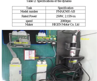
the tachometer. The CANoe monitoring equipment is used to monitor the motor speed, the current value of the q-axis, and the torque detection time. The motor and controller specifications are presented in Table 1. The dynamo specifications are presented in Table 2.
Table 1: Specifications of the motor and controller Task Specification
MOTOR
Model number MAXON EC-4Pole Electric resistance 0.386Ω
Inductance of d-axis 0.0653mH Inductance of q-axis 0.0653mH Torque Constant 0.0276Nm/A
Rotor Inertia 0.00000333㎏㎡
Pole Pair 2 Magnetic flux 0.0092V.S CONTROLLER
Operating type Sinusoidal control rated phase current 100A
DC Link Voltage 48V Table 2: Specifications of the dynamo
Task Specification Model number FMAKN05-AB
Rated Power 250W, 2.15N-m speed 2000rpm Maker HIGEN Motor Co. Ltd
Fig. 2: Picture of the experimental system environment
2) Result The proposed algorithm was verified by measuring the time to detect various loads applied under various conditions such as low speed and high speed. The detecting time depending on the motor speed when a load is
Motor
Load
Debug Controller
SW Panel
Canoe
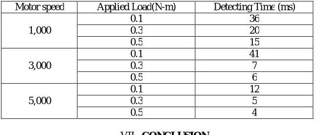
applied to the motor, is presented in Table 3. If a speed PI controller is used, the speed does not change due to the performance of the speed PI controller. So, the motor speed was adjusted according to the current reference of the q-axis. That is, the motor speed is the result of the current PI control.
Since the speed fluctuation is large when the motor rotates fast, the load detection time of the system drops. At low speed, the load detection was good, but load detection time was long. At high speed, the load detection was not good because of the variation range of the speed, which includes noise components such as inertia and production deviations of the motor.
Table 3: Detecting time depending on speed and load
Motor speed Applied Load(N-m) Detecting Time (ms) 1,000
0.1 36 0.3 20 0.5 15 3,000
0.1 41
0.3 7
0.5 6
5,000
0.1 12
0.3 5
0.5 4
VII. CONCLUSION
The PMSM is widely used in industry. For the detection of faults and monitoring of the system, it is important to detect changes in the load in systems in which a PMSM is installed. However, the price of sensors is expensive and it is difficult to install sensors because of space limitations. Therefore, a method to detect load using the speed of the motor in a system without a sensor is proposed. The FOC method for operating the motor is studied and a detecting method using the speed fluctuation is studied. However, the speed includes many error components such as motor inertia and measurement errors. To improve the accuracy of the speed measurement, the pulse count method is implemented. Actual experiments were performed to verify the proposed algorithm. The proposed algorithm detects load variation at approximately the same time as an actual load is applied.
VIII.ACKNOWLEDGEMENT
This research was supported by the Ministry of Trade, Industry & Energy(MOTIE), Korea Institute for Advancement of Technology(KIAT) through the Encouragement Program for The Industries of Economic Cooperation Region) R0003913
REFERENCES
[1] D. H. Ban, S. H. Jin, and J. S. Hong, “The study about the load sensing method of BLAC motor,” 2016 Proceeding of IEMEK, 304-306. [2] D. H. Ban, J. S. Hong, and S. H. Lee, “Diagnostic of the inverter / the motor using DC current,” 2016 Proceeding of ICROS.
[3] B. J. Lim, and C. D. Park, “Development of Load apparatus for Motor,” KSFM journal, 12(6), 2009, 26-32.
[4] C. H. Jo, S. H. Hwang, and H. S. Kim, “Estimation of Clamping-force and Development of Gap-distance Control Algorithm for Electro-Mechanical Brake,” 2009 Proceeding of KSAE, 665-670.
[5] Y. D. Kiran, P. S. Puttaswamy, “Field Oriented Control of a Permanent Magnet Synchronous Motor using a DSP,” International Journal of Advanced Research in Electrical, Electronics and Instrumentation Engineering, 3(10), 12364-12378, 2014.
[6] D. H. Ban, S. H. Lee, and J. S. Hong, “Rotor Position Estimation of Permanent Magnet Synchronous Motors Using Low-Resolution Sensors”, International Journal of Fuzzy Systems,Vol. 19, No. 1, pp. 78-85,2016
[8] X. G. Yan, and C. Edwards, “Nonlinear robust fault reconstruction and estimation using a sliding mode observer”, Automatica 43, pp.1605-1614, 2007
[9] J. I. Ha, K. Ide, T. Sawa, and S. K. Sul, “Sensorless Rotor Position Estimation of an Interior Permanent-Magnet Motor From Initial States”, IEEE TRANSATIONS ON INDUSTRY APPLICATIONS, Vol.39,No.3, pp.761-767, 2003
[10] R. Wu, and G. R. Slemon, “A Permanent Magnet Motor Drive Without a Shaft Sensor”, IEEE TRANSACTION ON INDUSTRY APPLICATIONS,Vol.27,No.5, pp.1005-1011, 1991
[11] C. S. Li, and M. Elbuluk,“A Sliding Mode Observer for Sensorless Control of Permanent Magnet Synchronous Motors”, Industry Applications Conference, 2001. Thirty-sixth IAS Annual Meeting Conference Record of the 2001 IEEE,Vol.1,pp.1273-1278,2001
[12] Y. Feng, J. Zheng, X. Yu, and N. V. Truong, “Hybrid Terminal Sliding-Mode Observer Design Method for a Permanent-Magnet Synchronous Motor Control System”, IEEE TRANSACTIONS ON INDUSTRIAL ELECTRONICS,Vol.56,No.9, pp.3424-3431, 2009
[13] B. K. Kim, W. K. Chung, and K. Ohba, “Design and Performance Tuning of Sliding-Mode Controller for High-Speed and High-Accuracy Positioning Systems in Disturbance Observer Framework”, IEEE TRANSACTIONS ON INDUSTRIAL ELECTRONICS,Vol.56,No.10, pp.3798-3809, 2009
BIOGRAPHY
Donghoon Ban He received the B. S. degrees in electrical engineering from Donga University, Busan, Korea in 1999; the M.S. degree in electrical engineering from Pusan University, Busan, Korea in 2006; and the Ph. D. degree in electrical engineering from Donga University, Busan, Korea in 2013. He is a senior research engineer at Daegu Gyeongbuk Institute of Science & Technology(DGIST). He is developing the components of vehicles such as Body Control Module, Electronic Parking Brake, and Electronic Mechanical Brake base on AUTOSAR. His research interests are Fuzzy control, PMSM control, inverters and AUTOSAR.