Semiautomatic Drilling Machine Controller
Vishal Shinde1, Prof. R. N. Panchal2, Prof. J.R.Panchal3
Student, Department of Electronics and Telecommunication, Siddhant College of Engineering, Savitribai
Phule Pune University, Pune, India1
Professor, Department of Mechanical Engineering, JSPM'S Rajarshi Shahu College of Engineering, Tathawade,
Savitribai Phule Pune University, Pune, India2
Guide, Department of Electronics and Telecommunication, Siddhant College of Engineering, Savitribai Phule
Pune University, Pune, India3
ABSTRACT: For precise job manufacturing, system should possess good dimensional accuracy and surface finish. In applications like drilling, punching, marking, boring, tapping work piece is positioned firstly and then cutting tool performs its action while motion axes are kept stationary. In traditional approach for such applications, manufacturer uses highly expensive CNC machine for programming job cycle and executing the same. Big scale manufacturer can afford such highly expensive machines but for small scale mechanical job manufacturing industry we have to think of low cost solution that can deliver high class output. In this paper we are trying to propose low cost design using which similar functionality as that of CNC can be achieved. This examination depicts control arrangement of a programmed boring machine. Three engines are utilized to move the tomahawks, for example, X, Y, and Z. They are set fit as a fiddle on the casing. PIC16F1939 is utilized to look at the yield voltage from the engine driver circuit. PIC creates yield sign to the LCD and engines. LCD (16x4) is utilized to show the estimations of X, Y, Z arranges that mean to bore. By utilizing LCD, client can know which focuses are bored on the item. DC engine is utilized to penetrate the item when directions achieve their qualities. This framework is, particularly, used to make (PCB) printed circuit board in industry. By applying this machine underway industry, it can acquire the multi generation brief time.
KEYWORDS: Microcontroller, Stepper Motor, DC motor, Embedded C
I. INTRODUCTION
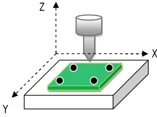
Y, Z hub arrives or not in their positions to begin the boring procedure. In the event that the three tomahawks are at zero position, it will be begun to move and bore. The drill down to the item to make the gap on the craved position and after that penetrating procedure is finished. This operation can make the production line mechanization to be a finished procedure. The LCD (16x4) is utilized as the yield show. It can be presentation the name of the machine, the X, Y, Z values and penetrate result. Appropriate penetrating procedure is expected to guarantee their position maintainability is really being come to. Coordinate system of a programmed drilling machine is appeared in Figure 1.
Figure 1: Co-ordinate Systems of Machine
Explanation-
In proposed design operational unit will have three operating modes
1. Program Mode – Unit will be programmed with predefined operation cycle for drilling or boring process. Programming can be done offline on the PC.
Program Mode involves following actions.
a. Creating a program on PC using software utility. Here user can set the sequence of XY coordinates for various drill positions.
b. Downloading the created programs into flash memory over UART
2. Run Mode – Here drilling process can be automated or can be done manually. In semi auto mode operator will select the program for job for the execution. In manual mode, user manually sets XY coordinates or adjusts drill tool’s position using keys provided on panel.
3. Configuration Mode – Here machine’s configuration related parameters can be set manually.
II. PRINCIPLE OF POSITIONING
By mechanical means viz. racks and pinions or lead screws and stepper motor, one can measure straight-line or linear motion. Here we will be using lead screw for translating turning motion into linear motion. It is often assumed that the pitch (threads per linear distance) is precisely known. This assumes the pitch is constant at every location along the lead-screw.
Z
X
Figure 2: Motor and Lead Screw Coupling
Based on the Pitch of the lead screw &No of steps generated per revolution by the stepper motor used in the system can be calculated using formula below.
Resolution = (Pitch) / (Steps per Revolution)
III. SYSTEM OPERATION
In this research, the control system of an automatic drilling machine actuated with DC motor and stepper motors are designed and implemented; and driven from program developed for controlling the designed drill machine. The keypad is used to control system of an automatic drilling machine. Firstly, the object must be placed on the board. The sensor will sense the X, Y, Z axis arrives or not in their positions to start the drilling process. If the three axes are at zero position, it will be started to drill. It has main three modes of operation,
(a) Program Mode – Program job drill positions
(b) Run Mode – Execute the program for taking drills at desired positions (c) Configuration Mode – Configuration of machine parameters.
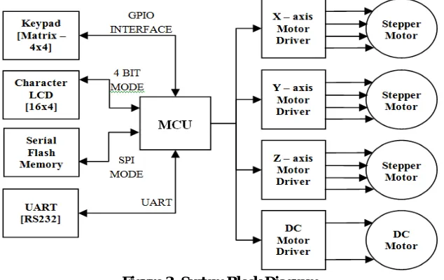
IV. SYSTEM BLOCK DIAGRAM
Drilling machine controller is developed on the embedded platform. Refer the Figure 3 for block details of block diagram.
Stepper Motors and DC motor: Three motors will be coupled to lead screw in order to provide linear motion to Drill System along XYZ plane. DC motor is used to actuate drilling tool. For home position sensing limit switch inputs are given to controller.
CPU: This block is the heart of the system. It takes care of all controlling actions required in order to position the drilling machine. It manages external world peripheral interfaces like LCD, Keypad, Flash Memory, UART etc.
LCD DISPLAY: LCD display provides interactive user interface. It shows all selected program parametric information also alert messages during program cycle mode.
FLASH: It is used to store the programs containing XY position details of the Job to be drilled..
KEYPAD: It is used for screen navigation and manual drill machine position control.
UART: To copy programs developed offline on the PC into Flash Memory.
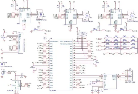
V. HARDWARE COMPONENTS OF THE SYSTEM
The control system of an automatic drilling machineintends to use in manufacturing industry.. In control system of an automatic drilling machine, the simple case includes the drill tool, drill holder, PIC16F1939, keypad, DC motor, stepper motor, andLCD. The drill tool consists of the driven mechanical devices attached to the end of the holder, by which objects can bedrilled. In the manufacturing system, three steppers motorand one DC motor are existed. One stepper motor is mountedin X axis, second is attached to the Y axis, the third one isimplemented in Z axis and a dc motor attached to the axis ofthe drill manipulator is used to drill hardboardprogrammatically. Drill tool works as a method of work partdrilling. Model of drilling machine is constructed to drill the object from the drill hardboard. Refer the schematic given in figure 4 for more details.
A.PIC16F1939 Microcontroller
Microcontroller is a computer on a chip that is programmed to perform almost any control, sequencing,monitoring and display the function. Because of its relatively low cost and its great advantage is no other externalcomponents are needed for its application because allnecessary peripherals are already built into it. Thus we cansave the time, space and cost which is needed to constructlow cost devices.
B. Stepper Motor
A stepper motor (or stepping motor) transforms appliedvoltage pulses into discrete motions called steps. It allowsprecise control of position and speed without, generally, theneed of feedback. This reduces the complexity of the control.The rotation director is decided by the order of windingexcitation. In this operation system , to move along X axisfrom rear to front, Y axis from south to north and Z axisfrom up to down and down to up, stepper motor is installedfor each in this control system of an automatic drillingmachine. L298 driver is operated to drive the stepper motor.The operating voltage of stepper is chosen as the 12V toaffect powerfully the whole system.
C. Brushed DC Motor
Brushed DC motor types have some performanceadvantages over direct-current, excited, synchronous types,and have become predominant in fractional horsepowerapplications. They are smaller, lighter, more efficient andreliable than other electric machines. In this research, one DCmotor is used for drill. The motor selected for MSR is the12V DC motor. To drive motor with limited voltage andcurrent, there are many drivers. But this motor is driven withone transistor for one direction from output PIC controller GPIO pin.
D. L298 Motor Driver
The L298 is an integrated monolithic circuit in a 15 lead Multipart. It is a high voltage, high current dual full-bridgedriver and drive inductive loads such as relays, solenoids, DCand stepping motors. In this drilling system, three
L298drivers are used to drive three stepper motors which for X, Y,Z coordinates. In this driver, 1KΩ resistors are used
toconnect with pin 6 and 11. Pin 9 feed +5V and pin 4 feed+12V. Pin 1,8,15 are ground pin and pin 2, 3, 13, 14 areconnected for each stepper motor winding.
E. LCD Display
The LCD (16x4) characters is used to display the values ofX, Y, Z coordinates. The pins of LCD (16x4) are connectedwith the PIC output pins. RS pin is the register select signalwhich is connected to the PIC output pin RE1. E pin is usedto connect with RE0 from PIC output. D4, D5, D6 and D7 arethe Data bus pins of LCD. They are used to connect withRA4, RA5, RA6 and RA7 from PIC output. Pin diagram ofLCD (16x4) is shown in Fig.3.
This operation can make the machine automation to be acompleted process. The LCD (16x4) is used as the outputdisplay. It can be display the name of the machine, the X, Y,Z values and drill result. The microcontroller controls themotors to reach for drill to specified position. Firstly, usercommand the position for X and Y axis by using keypad.Thesensor will sense the signal to the microcontroller for startingposition of X, Y axis. When they reach their position, Z axisdown to the workplace and start to drill the object. Then the drilling process is completed. LCD displays the values of X,Y, Z coordinates.
VI. SOFTWARE IMPLEMENTATION OF THECARTESIAN TYPE DRILLING SYSTEM
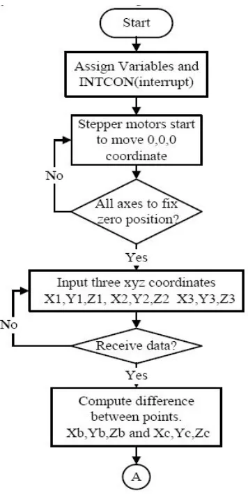
In software execution, after power up all variables and flags are set to their default values.
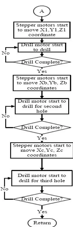
MCU peripheral like UART, SPI, GPIO, Timer are initialized. In the program, signed the variables which are used forvarious data, sensor data and USART data. Then all axes are moved to home position using stepper motor drive and limit switch sense mechanism. Once system is calibrated (home positioning is completed), the controllerwaits for drill position X, Y, Z. User either selects the program for coordinate input or he manually sets the values. Then X, Y, Z-axes are moved from zero position to the desire position to create the hole on the object which is situated on themachine. And the drill tool is drilled the object and back tithe up position. In semiautomatic mode these three stepper motors start again to drill another hole on the object. Then all X, Y, Z motors move to home position after finishing the drilling process. And the program is looping for next process. Overall flowchart of the system is shown in Figure 7 and Figure 8
Figure 8. Overall flow chart of the system.
In this operation system, embedded C programming language is used for the firmware development. MPLAB IDE and cross complier for PIC16FXXXX are used for the software development.
VII. DISCUSSION AND CONCLUSIONS
programming dialect. For future result, the outline and development can be enhanced by making auto composing circuit lines. Understanding this control framework, other engine control framework can be created in commercial ventures. In cutting edge gadgets, this control arrangement of a programmed penetrating machine can be redesigned with other control framework for more accuracy and more conservativeness.
REFERENCES
[1]. May PhuePhueLwin ,KyawThiha “Control System of An Automatic Drilling Machine” International Journal Of Scientific Engineering and Technology Research Issn 2319-8885, Vol.03,Issue.19, September-2014, , Pages:3951-3955.
[2] A.Karthik 1, R.Krishnaraj “Single Axis Semi-Automatic Drilling Machine WithPlcControl” International Journal of Innovative Research In Science, Engineering And Technology (An Iso 3297: 2007 Certified Organization) Vol. 4, Issue 3, March 2015.
[3] P.A.Mehta “Automatic Drilling System Using Plc” International Journal For Technological Research In Engineering Volume 1, Issue 7, March-2014.
[4] GautamJodh “Design Of Low Cost Cnc Drilling Machine” International Journal Of Engineering Research And General Science Volume 2, Issue 2, Feb-Mar 2014 Issn 2091-2730.
[5] ShaikhNoorfarooque “Automated Pcb Drilling Machine With Efficient Path Planning” International Journal Of Advanced Research In Computer And Communication Engineering Vol. 4, Issue 4, April 2015
[6]. H. Ferdinando, I. N. Sandjaja, G. Sanjaya, “Automatic DrillingmachineFor Printed Circuit Board” Proceedings Of The 6thsymposium On
Advanced Intelligent Systems, Surabaya Indonesia2005, Pp. 218-222.
[7]. N. Balasubramanyam_And Prof. Smt. G. Prasanthi “Design Andfabrication Of An Automatic Pc-Based Drilling Machine”,Hctlopen International Journal Of Technology Innovations Andresearch, Volume 7, January 2014.
[8]. ShrikantBhange, LochanaAhire, Madhuri Gadkari, Asmitabhosale, MansiShrimali Pc Controlled PcbDrillingmachine” International Journal Of Engineering Technology Andcomputer Research (Ijetcr), Volume 3; Issue 1; Page No. 64-66.
[9] Hu Van Thoi, ―Design And Build an Automatic PCB Drilling Machine
[10]Yung C. Shin, Henry Chin, Michael J. Brink, ―Characterization Of Cnc Machining Centers, Journal Of Manufacturing Systems, Volume 10,
Issue 5, 1991, Pages 407-421.
[11] Kirtikumar, ―Research On Operating Of CncMachinIjtre, Vol. 1.
[12]Jaju, H. T. K. D. S. A Review On Material Handling & Clamping System For Wear Plate Welding Machine.TableOfcontent Topics Page No, 85.