WEI, BIN. Modification of Polymer/Polymer Interfaces Using Block Copolymers and Microgels. (Under the direction of Jan Genzer and Richard J. Spontak.)
A guest macromolecule, consisting of either a block copolymer (BCP) or core-shell microgel (MG) particles, has been used to stabilize a polystyrene (PS) film positioned atop a substrate of poly(methyl methacrylate) (PMMA) homopolymer, which is immiscible with PS. Modification of the PS/PMMA interface due to interfacial partitioning of the guest macromolecule significantly increases the stability of the PS film by either slowing down or completely eliminating dewetting of the top PS layer. It has been established that the PS dewetting rate depends on (i) the concentration of guest macromolecule, (ii) the PS film thickness and (iii) the annealing temperature. In general, the dewetting rate is observed to decrease with increasing BCP or MG concentration. The temperature dependence of dewetting can be expressed in Arrhenius form wherein the apparent activation energy is nearly independent of the molecular weight of PS and the concentration of BCP at low BCP loading levels (< 3 wt%). The stability of the PS films likewise increases with increasing film thickness. Near-equilibrium (late-stage) morphologies of dewetted films depend sensitively on the BCP concentration and PS film thickness.
PS/PMMA interface. At relatively low BCP and MG concentrations, high-temperature dewetting occurs by nucleation and growth of circular holes. Within this regime, accelerated hole growth is also observed as the BCP concentration is increased. A further increase in BCP concentration yields spinodal-like dewetting due to modification of the PS/PMMA interface by individual BCP molecules and micelles. At still higher BCP concentrations, the dewetting mechanism switches back to nucleation and growth of holes, albeit of irregular (non-circular) shape. The top film completely stabilizes (no dewetting is observed) when a sufficiently high level of BCP is added.
Due to the shape retention of the MG, autophobicity is observed between the MG particles with a PS-like core and PMMA arms and a chemically identical long-chain PMMA homopolymer. This behavior is attributed to entropic exclusion of the PMMA matrix polymer from the high graft density of PMMA arms. In agreement with theoretical predictions, the change in free energy (∆Fauto) due to autophobic segregation
of MG from the PMMA matrix is of the same order as typical polymer/polymer interfacial energy (γAB), but about an order of magnitude lower than typical polymer surface energy (γA or γB). By positioning a thin layer of PS on top of a PMMA/MG film,
we have demonstrated that autophobicity is strong enough to overcome the resistance of γAB so that the MG could be pushed from the PMMA matrix to the PS/PMMA interface.
surface roughening that accompanies autophobic segregation. Such MG-induced interfacial patterning in areas in contact with PS is completely reversible. Further annealing the PMMA/MG after the PS is removed permits the surface energy of PMMA to force the MG back into the PMMA substrate.
MODIFICATION OF POLYMER/POLYMER INTERFACES
USING BLOCK COPOLYMERS AND MICROGELS
by
Bin Wei
A dissertation submitted to the Graduate Faculty of North Carolina State University
In partial fulfillment of the requirements for the Degree of Doctor of Philosophy
Chemical Engineering
Raleigh, NC 2005
Approved by:
Dedicated to
Biography
Bin Wei was born on May 17th, 1971 in Huodekeng, a small village located in the mountains of Longyan County, Fujian Province, China. In 1978 he started his education at the local elementary school. Four years later he was transferred to Zhongjie Elementary School in the city of Longyan, thanks to his parents’ foresighted determination to provide him with the best education opportunity available. To this end, this decision of his parents has been the most critical turning point of his life. It gave him the possibility to compete and win the precious opportunity to attend Longyan No. 1 Middle-High School, one of the only two secondary schools in the city where hope of higher education existed.
Acknowledgments
From the bottom of my heart, I am grateful for my advisors, Dr. Jan Genzer and Dr. Richard J. Spontak. I feel fortunate to have the opportunity to work with them for the past few years. They are exemplary models of creative and enthusiastic researchers that I hope to emulate one day. I have benefited from them far more than their academic advice. Their sense of humor makes research work in the lab enjoyable.
I am thankful for my other advisory committee members, Dr. Alan Tonelli and Dr. John van Zanten, who have always been ready to help me. I would like to acknowledge the professors in the Department of Chemical & Biomolecular Engineering. They are a team of outstanding scientists whom I never had to hesitate to ask for advice or guidance. Particularly, I would like to thank Dr. Carol K. Hall, Dr. Saad A. Khan, Dr. Peter K. Kilpatrick and Dr. Gregory N. Parsons, in particular, for their kindness in encouraging and helping me.
I thank Dr. Paul A. Gurr, Dr. Gregory G. Qiao and Dr. David H. Solomon in the Polymer Science Group, Department of Chemical & Biomolecular Engineering, University of Melbourne, Australia. Cooperation with them on the investigation of microgel nanoparticles has been my great pleasure.
nice and helpful through the years. They have always given me smiles in addition to providing excellent service. The Graduate Secretary Ms. Sandra S. Bailey, assumes the role of a caring mother for the graduate students.
I want to acknowledge the members of my two research groups — the Genzer Research Group and the Polymer Morphology Group. Working alongside them has been truly enjoyable. They have been so very helpful in experiments, discussions, and presentation critiques. Specifically, I’d like to thank Rajendra R. Bhat, Julie A. Crowe, David J. Frankowski, James J. Semler, Michael R. Tomlinson, and Tao Wu, who have given me tremendous help and shared with me a lot of fun. Dr. Kirill Efimenko in the Genzer Research Group has been valuable resource of experience and skills.
I enjoyed the association with many of the graduate students and post-doc’s inside and outside the Department. Angelica M. Sanchez and Dr. Lauriane F. Scanu in Dr. Khan’s Rheology Group tutored me in rheometry, a significant part of my Ph.D. work, and have always been there to help whenever needed. Changwoong Chu in Dr. Parsons’ group has patiently tutored me in AFM. Shane E. Harton in the Department of Materials Science & Engineering has always quickly responded to my questions about polymers and characterization techniques.
Kuk Jhon, Xiangming Li, Changqing Lin, Haiqing Lin, Tao Liu, Deming Mao, Jason L. Stone, Xiaolei Sun, Xiaoyu Sun, Guangquan Wang, Yang Wang, Dawei Xu, Haiou Yang, Qian Zhang, and Li Zhou. My fellow club members in Toastmasters International have been invaluable mentors in helping me improve my communication skills, and International Bible Study at NCSU has been like my extended family.
Table of Contents
List of Figures ...ix
1
Introduction and Overview ... 1
1.1 Motivation and strategy ... 1
1.2 Wetting and dewetting ... 8
1.3 Structure and properties of microgels ... 15
1.4 Autophobicity ... 15
1.5 Surface patterning ... 18
References:... 22
2
Overview of Microgels ... 28
2.1 Introduction... 28
2.2 Stimuli-responsive Microgels ... 35
2.3 Core-Shell Microgels ... 39
2.4 Synthesis ... 41
2.5 Characterization ... 44
2.6 Applications ... 47
References:... 62
3
Dewetting Behavior of a Block Copolymer/Homopolymer Thin Film on
an Immiscible Homopolymer Substrate... 73
3.1 Introduction... 73
3.2 Experimental ... 76
3.2.1 Materials ... 76
3.2.2 Methods... 77
3.3 Results and discussion ... 78
3.3.1 Film stability and dewetting kinetics ... 78
3.3.2 Block copolymer and dewetting morphologies ... 88
3.4 Conclusions... 91
Appendix... 93
References:... 107
4
Tunable Instability Mechanism of Polymer Films by Molecular
Self-Assembly ... 109
References:... 122
5
Instability of Polymer Films on a Polymer Substrate with
Copolymer-Induced Interfacial Heterogeneities ... 124
5.1 Introduction... 124
5.2 Experimental ... 128
5.3 Results and discusion... 130
5.4 Conclusions... 141
References:... 149
6
Dewetting of Star Nanogel/Homopolymer Blends from an Immiscible
Homopolymer Substrate... 152
References:... 165
7
Patterning of Microgel Particles on Polymer Surface by controlling the
Autophobicity and Interfacial Tension ... 167
References:... 179
8
Conclusions and Recommendations ... 182
8.1 General remarks ... 182
8.2 Conclusions... 183
8.2.1 Compatibilization of immiscible homopolymer films with block copolymer .... 183
8.2.2 Effects of block copolymer on dewetting mechanism ... 186
8.2.3 Microgel used as stabilizer ... 187
8.2.4 Autophobicity and surface patterning... 188
8.3 Recommendations for Future Work... 190
8.3.1 Dewetting ... 190
8.3.2 Microgel... 190
List of Figures
Chapter 1
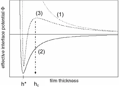
Figure 1-1 Schematic illustration of the dependence of effective interface energy φ(h) on film thickness. Three scenarios are shown: (1) Dotted curve, the minimum is at infinity and the film is stable. (2) Solid line, there is a minimum of energy at h*. The film is unstable and dewets via spinodal route. A thin layer of hequil is left on the solid substrate. (3) Dashed line, the film is unstable with low thickness (h < hc) and dewets spinodally. With relatively higher film thickness (h > hc), the film is metastable. Only nucleation and growth of holes can overcome the energy barrier and lead to film dewetting ………...……….. 21
Chapter 2
Figure 2-1 (a) Microgel particle collapsed in a poor solvent (χ12 > 0.5); (b) Microgel particle swollen in a good solvent (χ12 = 0). χ12 is the interaction parameter between the microgel and the solvent. ……… 56
Figure 2-2 Monomers most frequently used to synthesize microgel particles. The above monomers are (a) methylmethacrylate, (b) methacrylic acid, (c) styrene, (d) divinylbenzene, (e) acrylic acid, (f) N-isopropylacrylamide, (g) N,N′-methylene bisacrylamide and (h) ethyleneglycol dimethacrylate. ……….………. 57
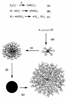
Figure 2-3 Process of SFEP to prepare microgels. (a) thermo decomposition of initiator; (b) initiation of polymerization; (c) propagation of chains; (d) particle nucleation; (e) particle growth; (f) collapse in and precipitation from the poor solvent of the polymer. …….……. 58
x
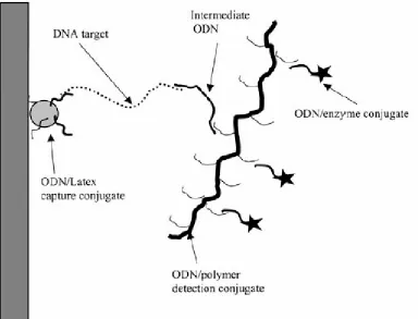
Figure 2-5 Schematic illustration of specific capture and detection of target DNA (or RNA) using latex-oligonucleotide (ODN) capture conjugates and copolymer-ODN detection conjugates. The ODN/latex conjugates are adsorbed on a 2-dimension solid support such as the inner wall of a pipette tip. The ODN hybridize with a part of the target DNA, which hybridize with an intermediate probe ODN. ……….. 60
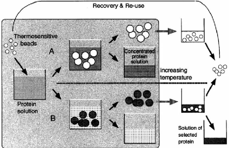
Figure 2-6 Protein concentration (A) and separation (B) using thermoresponsive polymer particles (e.g., PNIPAM). Process (A): Water swells the microgels so that the protein is concentrated in the substrate. The swollen microgel collapses when it’s exposed to a temperature above LCST after separated from the substrate. Water is squeezed out of the network in this recycle processing and the microgel is reusable. Process (B): Protein molecules are selectively adsorbed into the microgel particles, which are separated from the solution. After separation, e.g., by changing pH or salinity, from the protein, the microgel is reusable. ………. 61
Chapter 3
Figure 3-1 Illustration of the PS/SM+PMMA double-layer assemblies investigated in this work. The as-cast PS/SM layer depicted in (a) is presumed to possess a non-equilibrium morphology. Upon annealing at temperatures in the melt (b), this morphology is refined as (i) the copolymer molecules self-organize into micelles and migrate to the PS/PMMA interface and (ii) the PS top layer simultaneously dewets from the PMMA substrate. Individual SM molecules and SM micelles adsorbed to the PMMA substrate remain on the dry PMMA surface upon dewetting. ………. 96 Figure 3-2 Schematic depiction of the hot-stage set-up employed here showing the specimen area continuously illuminated by visible light or UV radiation during extended annealing times. ……….. 97
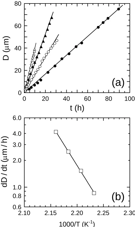
Figure 3-4 In (a), dependence of dewetted hole size (D) on time (t) for neat PS200 on PMMA281 at four temperatures (in °C): 175 (z), 180 ({), 185 (S) and 190 (U). The solid lines in (a) denote linear regressions to the data and yield the isothermal dewetting rate constant (dD/dt) at each temperature. In (b), dewetting rate constants as a function of temperature (T) illustrating Arrhenius-type behavior. The solid line in (b) is a fit of Eq. 4 to the data, which yields an apparent activation energy (Ea) of ≈180 kJ/mol. ……… 99
Figure 3-5 In (a), dewetting kinetics of PS200/SM (WSM = 0.12) on PMMA281 at three temperatures (in °C): 180 ({), 185 (S) and 190 (U). The solid lines in (a) denote linear regressions to the data in early- and late-stage dewetting regimes and yield dD/dt in each regime at each temperature. In (b), the temperature dependence of the early- and late-stage dewetting rate constants. The solid line in (b) corresponds to Eq. 4 in which Ea is set equal to 180 kJ/mol, whereas the dashed line serves to connect the data. ……… 100
Figure 3-6 The dewetting kinetics of (a) neat PS50 on PMMA226 at 180°C and (b) PS50/SM (WSM = 0.01) on PMMA226 at three temperatures (in °C): 180 ({), 185 (S) and 190 (U). The solid lines in (a) and (b) denote linear regressions to the data and yield dD/dt in at each temperature. Values of dD/dt are presented for the neat PS50 () and PS50/SM ( ) layers as a function of temperature in (c), wherein the solid line corresponds to Eq. 4 with Ea = 180 kJ/mol. ………. 101 Figure 3-7 The dewetting kinetics of (a) PS50/SM (WSM = 0.02) and (b) PS50/SM (WSM = 0.03) on PMMA226 at 180°C. The solid lines in (a) and (b) denote linear regressions to the data in early- and late-stage dewetting regimes and yield dD/dt in each regime at each temperature. Values of dD/dt for single and late-stage dewetting ({), as well as early-stage dewetting (z) are presented as a function of WSM at 180°C in (c), wherein the solid line is a fitted exponential function to the data. ……… 102
Figure 3-8 Representative AFM images of holes formed after annealing the PS50/SM layer (WSM = 0.03) on PMMA226 for 30 min at 180°C. The image in (a) displays the initial film rupture, whereas the one in (b) reveals a fully formed rims around the holes. The image sizes are 20 and 50 µm in (a) and (b), respectively. ………. 103
xii
micelles/brushes residing at the dry PMMA281 surface appear as dark features due to the RuO4-stained PS corona. ……….. 104
Figure 3-10 Experimental morphology diagram (expressed in terms of L and WSM) of the PS200/SM layer on the PMMA281 substrate after annealing at ≈180°C for 7 days: non-dewetted PS200/SM layer with bulk SM micelles (z), weakly dewetted PS200/SM layer with bulk SM micelles (S), finely connected PS200/SM filaments (), connected PS200/SM islands with surface SM micelles ({), isolated PS200/SM islands with surface SM micelles (U) and discrete PS200/SM islands with bulk and surface SM micelles ( ). ………. 105 Figure 3-11 Profilometry of dewetted PS200/SM islands on PMMA281 (a) with and (b) without exposure to visible light during annealing for 6 days at 180°C. ……….. 106
Chapter 4
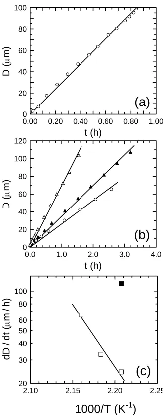
Figure 4-1 Optical images of a PS/SM5 thin film on PMMA at 180°C after different times (t, in min): (a) 2, (b) 10, (c) 20, and (d) 95. The scale marker in (d) corresponds to 20 µm. An AFM height image of the PS film surface (inset) shows holes measuring 0.7-1.0 µm across after 2 min. ……….… 118
Figure 4-2 In (a), the time dependence of the fastest-growing wave vector (qt*), normalized relative to qt* at 2 min (q0*), for PS/SM4 and PS/SM5 thin films on PMMA at 180°C. The solid line is a power-law fit to the data. The inset in (a) is an AFM height image of the stripped PS/PMMA interface and displays interfacial elements measuring 90-300 nm across after 2 min. In (b), a TEM image of a PS/SM5 thin film on PMMA after 5 min at 180°C confirms the existence of copolymer structures measuring ca. 90-280 nm across. The inset in (b) is a 3x enlargement. ………..…………. 119
Figure 4-3 Variation of D(t) for thin PS and PS/SM7 films dewetting on PMMA at 180°C (note the different upper and lower time scales). The optical image with a 20 m scale marker shows a flower-like hole in the PS/SM7 film after ~40 h. The solid lines are regressions of Eq. 1 to the PS and early-stage PS/SM7 data, whereas the dashed lines are linear regressions to all the data sets. ………... 120
PS/PMMA interface before accelerated dewetting. Accelerated dewetting rates are also included when relevant ( ), and the solid line is a guide for the eye. AFM height images of the PS-stripped PS/PMMA interface display copolymer elements measuring 50-300 nm across after 18 h (Regime I), 24 h (Regime II) and 100 h (Regime III). The illustrations are discussed in the text. ………. 121
Chapter 5
Figure 5-1 (a) Schematic double-layer structure of a film before annealing, with PS50k and SM blend in the top layer (~ 67 nm thick) and PMMA 226k in the bottom layer; (b) Schematic cross-section illustration of a dewetting hole, with micelles, surface micelles and interfacial SM patches shown. ……….. 143
Figure 5-2 Dependence of dewetting morphology on block copolymer concentration. SM1wt% (a) – (e), nucleation and growth of circular holes with sporadic SM patches along the PS/PMMA interface, the annealing time is 10, 30, 65, 145, and 195 minutes, respectively; SM 5wt% (f) – (j), spinodal-like dewetting pattern due to heterogeneities of SM formed along the PS/PMMA interface, the annealing time is 2, 20, 62, 109, and 1219 minutes, respectively; SM 7wt% (k) – (o), nucleation and growth of irregular holes due to high population of SM patches along the interface, the annealing time is 15, 20, 36, 42, and 46 hours, respectively. ……….. 144
Figure 5-3 Dependence of hole size on time for dewetting of PS50k, PS50k+SM1wt%, and PS50k+SM7wt%, respectively, from PMMA 226k. The Black solid lines are fitted with partial-slip equation (1), which gives marginally better fitting than linear fitting of the dashed lines. ……….. 145
Figure 5-4 (a) Fast Fourier Transform of a dewetting pattern of SM 5wt%; (b) Exponential dependence of wave vector of the dewetting pattern on annealing time (for t < t’). The slope of the linear fitting is -0.332±0.004. ………. 146
xiv
patterning with medium concentration of SM (4-5wt%); and Regime III, nucleation and growth of irregular holes due to high population of SM molecules along the PS/PMMA interface. There is another Regime IV, which corresponds to completely stabilized film by SM of high enough concentration. ... 147
Figure 5-6 (a)-(c) AFM images of PS/PMMA interface scanned after washing away the top layer of PS; (a) SM 2wt%, sporadic SM patches; (b) SM 5wt%, pattern formed by SM patches; and (c) SM 7wt%, high population of SM patches. (d)-(e) TEM’s of SM 5wt%, annealed for 5 minutes and 15 minutes, respectively. In (d) and (e) micelles as well as SM patches are visible. (PS is stained to enhance the contrast.) Distribution of micelle size demonstrates that formation of block copolymer micelles in a homopolymer matrix is a kinetic process. (f) Tilt-sample TEM of SM 5wt%, annealed for 15 minutes. This type of image allows analyzing distribution of objects in z direction. Image (f) verifies the location of micelles and SM patches along the PS/PMMA interface. ……… 148
Chapter 6
Figure 6-1 Time-resolved optical microscopy images (using phase-contrast and Nomarski optics) acquired from PS/PMMA double-layer assemblies possessing different concentrations of NG particles (in wt%) in the top PS layer: 0 (top row), 3 (middle row) and 20 (bottom row). The corresponding annealing times (in min) at 180°C are 5, 30, 60, 90 and 120 in the top and middle rows, but only 5, 10, 15, 20 and 25 in the bottom row. ………... 161
Figure 6-2 Dependence of hole diameter (D) on annealing time (t) at 180°C for PS/PMMA double-layer assemblies containing different concentrations of NG particles (in wt%) in the top PS layer: 0 ( ), 3 ({) and 20 (U). Included for comparison are data collected from assemblies with different concentrations of SM diblock copolymer (in wt%) in the top PS layer: 1 (S) and 3 (z). The solid and dashed lines are linear regressions to the data, and the corresponding slopes yield the dewetting rate (dD/dt) discussed in the text. ... 162
and appears rough, whereas those displayed in (c) and (d) are obtained from a PS island, located between the dark lines evident in (c), and an adjacent hole (t = 90 min). Each image measures 10 m across, and the scan height is 20 nm/division. ………. 163
Figure 6-4 Schematic illustration of the mechanisms by which (a) NG particles and (b) block copolymer micelles residing in the top polymer layer reduce the rate at which the top layer dewets from the bottom polymer layer. In (a), we assume that the dangling arms comprising the coronal brush are much lower in molecular weight than the substrate polymer to ensure autophobicity so that the NG particles locate at the polymer-polymer interface. ………..………. 164
Chapter
7Figure 7-1 (a) Schematic illustration of dewetted PS islands and microgel aggregates at the PMMA/PS interface; (b) – (e) AFM images, scanned on the PMMA-MG surface after the sample had been annealed at 180°C and then the PS layer was washed. The scan size of each image is 5x5 µm2
and the height bar corresponds to scanning depth of 30 nm. (b) PMMA-MG free surface, with no PS coverage originally; (c) PMMA-MG area under a PS island, of which the sample had been annealed for 80 hours; (d) PMMA-MG area under a PS island, of which the sample had been annealed for 20 hours; (e) PMMA-MG area under a PS island, the sample had been annealed for 80 hours and was further annealed for 40 hours after the PS islands were washed away………..………...177
1
1
Introduction and Overview
1.1
Motivation and strategy
In nearly every technological field, the creation of stable thin films is of crucial importance for a variety of applications, including, but not limited to, paints, coatings, membranes, lithographical films, lubricants, surfaces in microfluidics, and biosensors.1-6 While most of these applications require complete wettability of the substrate by the coating material, non-wettability may be desirable in other applications such as in the development of self-cleaning surfaces capable of removing water and dust particles.7 Hence, achieving tunable control of surface wettability is necessary for the proper functioning of many technologies. Such control therefore requires a fundamental understanding of the mechanisms, as well as the dynamics, of wetting/dewetting processes.
Second, the glass transition temperature (Tg) of various polymers facilitates characterization of the wetting/dewetting process. When heated to temperatures above Tg, polymers behave as viscoelastic liquids so that wetting/dewetting processes can transpire and their dynamics can be studied. When cooled down to temperatures below Tg, wetting/dewetting processes are halted and the non-equilibrium morphology of the polymers can be “frozen” in place so that ex situ analyses can be conveniently performed. This liquid/solid duality has already been exploited in numerous studies designed to elucidate wetting/dewetting phenomena in thin polymer films.2-4
Early studies of polymer dewetting typically involved probes of a single-component polymer film on a solid substrate.4 Presently, more complicated dewetting systems have come under investigation. One such system involves the dewetting of a homopolymer (hA) film from a “liquid” substrate composed of an immiscible homopolymer (hB). These studies are motivated by numerous applications involving the stability of multilayer polymer films utilized in several technological applications, e.g., printing picture paper and coatings. As a consequence of previous efforts that have examined such systems, the dewetting rate, as well as the dewetting mechanism, are known to depend on factors such as film thickness, surface energies of the two components, interfacial energy between the two polymers, and viscosities of the homopolymers.
3
In addition to the block copolymer, core-shell microgel (MG) particles are also explored as an alternative compatibilizer for the homopolymer films in our dewetting investigation. The MG is a nanoparticle with a crosslinked core of divinylbenzene (DVB) and an outer shell composed of short PMMA arms. Due to their three-dimensional structure, MG particles possess unusual rheological properties and have been widely used as additives to adjust the rheological properties of paint and personal care products. More recently, the responsiveness of microgels to environmental conditions has attracted much attention. It has been established that microgels can undergo sharp volumetric changes (i.e., a volume phase transition, VPT) when environmental conditions such as pH, temperature, and ionic strength are altered. Their responsiveness to external stimuli makes MG particles excellent candidates as “smart materials,” thus showing promise in potential applications as controlled drug-delivery vehicles and as immobilization/separation biomaterial substrates.
5
stretched chains that are anchored to the core-shell interface. This high-density MG “brush” may not mix, and therefore remains immiscible, with long-chain PMMA, despite their identical chemical composition. This behavior is analogous to the autophobicity that occurs between a long-chain homopolymer and a brush of the same polymer grafted to a flat solid surface. Due to an increase in translational entropy in confined systems, the brush chains must stretch away from the confining substrate to accommodate the matrix homopolymer within the brush. However, an additional entropy penalty associated with such stretching does not allow for such stretching, in which case only limited (if any) mixing occurs between the brush and free homopolymer chains. This entropy-induced immiscibility is referred to as the autophobic effect, in which two chemically identical macromolecules do not mix. Autophobicity is unique to polymeric materials and can be one of the mechanisms that promotes the instability of polymer films. While autophobicity between a polymer brush anchored to a flat solid surface and a homopolymer has been well studied, so far there are no reports regarding autophobic behavior between a brush anchored to a curved surface, as in the case of a MG particle, and a homopolymer.
resistance from strong polymer surface energy, γPMMA, to polymer/polymer interfacial energy, γPS/PMMA, which is an order of magnitude weaker. Utilizing the aforementioned liquid/solid duality in polymers, we anneal the system at elevated temperatures above the highest Tg and then cool the system below the lowest Tg. Removal of the sacrificial PS layer is achieved by using a selective solvent (cyclohexane) so that the PS/PMMA interface can be exposed and the interfacial topography can be established via techniques such as atomic force microscopy (AFM). Reproducible AFM scans of specimens after PS removal reveal the presence of MG particles and aggregates that have segregated from the PMMA matrix to PS/PMMA interfacial areas below the dewetted PS islands. The PS/PMMA interface is significantly roughened due to the weak resistance of γPS/PMMA, whereas the dewetted “dry areas” remain smooth because of the strong resistance of γPMMA. Our experiments also demonstrate that the interfacial roughening by MG particles is reversible. By further annealing a sample with the PS layer removed, we can force the MG particles to “dive” back into the PMMA matrix so that the film surface smoothness is recovered. In short, it is reported herein that MG particles and long-chain PMMA are incompatible due to autophobicity. By simply switching the resistance between surface energy and interfacial energy, we can reversibly control the ability of the MG particles to be either “pushed” out of the matrix by autophobicity or “pressed” back into the matrix by surface energy.
7
the ridges of the wrinkles in the stamp could be easily transferred onto the surface PMMA/MG films. While the weak interfacial energy γPMMA/PDMS allows MG particles to protrude from the PMMA layer and roughen the interface in the “stamped” areas, the free surface areas (corresponding to the valleys in the stamps) remain free of MG particles. This observation may open a simple, low-cost route to controlled surface patterning of nano-scaled microgel particles. By using a stamp with an arbitrary pattern, the MG particles can be distributed on the homopolymer surface in the same pattern. Moreover, the segregation of MG particles to the PMMA/PDMS interface is again found to be totally reversible. As achieved previously, annealing the film with the PDMS stamp removed results in MG particles that are pressed back into the bottom layer of the PMMA matrix so that the surface again smoothens. This reversible surface patterning of MG particles warrants further investigation. Considering the robust structure of the MG particles, it seems feasible that they can be chemically altered. For example, one could load the crosslinked cores of the patterned MG particles with semiconducting (Cd-based) nanoparticles and obtain controlled patterning of quantum dots.
segregation, we can reversibly control the ability of the MG particles to migrate to the film surface and return back into the matrix. A stamping route is developed to provide proof-of-concept for controlled reversible patterning of MG particles on homopolymer film surfaces.
1.2
Wetting and dewetting
The stability of a liquid film on a solid substrate is determined by the effective interface potential ∆G(h) (per unit area), which is defined as the excess free energy required to bring the liquid surface from infinite distance to the film thickness (h).1,8-10 The excess free energy ∆G(h) is determined by the combined effects of long-range van der Waals attraction force and short-range polar repulsion. Quantitatively, ∆G(h) is defined as11-16
p pe d hl
S h A h
G ( )
12 )
( =− 2 + 0−
∆
π (1)
where A is the Hamaker constant, h is the film thickness, Sp is the strength of polar repulsion, d0 is the Born repulsion distance, and lp is the hydrophobic attraction distance (for polymer films, lp≈Rg, where Rg is the radius of gyration of the polymer coil). The first term in equation (1) is the van der Waals force, and the second represents the polar repulsion force.
9
the case when the film is stable, since ∆G > 0 for all thicknesses and the global minimum of ∆G locates at infinite distance. For curve (2), there is a global minimum of ∆G at a
thickness of h*, and ∂2∆G/∂h2
< 0 for all the thicknesses wherein h > h*. The excess free energy can be minimized if the film changes thickness from h to h*. If the initial film thickness is h > h*, the film is unstable and dewets from the substrate by a spinodal dewetting mechanism. In case (3), there exists a local maximum of ∆G at hc, as well as a global minimum at h*. For a film with h* < h < hc, one finds that ∂2∆G/∂h2
< 0 and thus the film is unstable and can likewise dewet by a spinodal mechanism. If h > hc, however, an energy barrier develops and the film becomes metastable. Nucleation and growth of holes around heterogeneous defects (dust or trapped gas) or thermal (homogeneous) nucleation can overcome the energy barrier and promote film dewetting by nucleation and growth of circular holes.17
In terms of “macroscopic” surface topography, the polymer depleted from the holes accumulates along the hole perimeter and forms a rim around the hole during nucleation and growth. The holes continue to grow until the rims of neighboring holes merge into each other, and the film evolves into a network composed of polygonal holes. This regime is followed by the breakdown of network ribbons into isolated droplets due to Rayleigh instability. Eventually the droplets becomes spherical caps at equilibrium and hence the equilibrium contact angle θ can be measured by AFM.4,18-20
In fact, the excess free energy ∆G can be related to measurable macroscopic parameters. As early as 1938, Frumkin21
θ
γ 1 cos
*) ( = − ∆ l h G (2)
where γl is the surface energy of the liquid. From a macroscopic viewpoint, the Young’s contact angle is defined as
sl l s γ γ γ θ)= −
cos( (3)
where γs, and γl represent the surface energies of the solid substrate and the liquid, respectively, and γsl is the solid/liquid interfacial energy. Using the surface/interfacial energies, a macroscopic counterpart of ∂2∆G/∂h2
is defined as the “spreading parameter” (S) where S = γs − (γl + γsl). This parameter can be conveniently used to judge the stability of a film. If S < 0, the film is unstable and dewets from the substrate. Otherwise, the film remains stable.6
Other than the contact angle, the free excess energy ∆G can also be linked to the wave length (λs) and relaxation time (ts) of a film undergoing spinodal dewetting, two other “macroscopically” accessible parameters:8,22
) /( 8 ) ( 2 2 h G h l s ∂ ∆ ∂ − =π γ
λ (4)
2 2 2 3 ) ( / 12 h G h
ts l ∂
∆ ∂
= µγ (5)
11
taking the fast Fourier transform (FFT) of a spinodal pattern, which results in the primary wave vector (q*) of the surface modulation. Subsequently, q* can be related to λs by 2π/q*.12,23-25 If a film undergoes spinodal dewetting (∂2∆G/∂h2
< 0), the amplitude of the primary capillary-wave fluctuation of the film surface, with a wavelength λs determined by Eq. 4, exponentially increases with time.18,22,26,27 The spatiotemporal evolution of the surface modulation can then be represented by12,22,28-31
iqx
he h t x
h( , )= 0 + (6)
where x is the in-plane coordinate, h0 is the initial film thickness and q is the wave vector. When the depth of the fluctuation valley reaches the film thickness at time ts, the film ruptures in the depressions and dewets from the substrate. After the film ruptures and holes form, the dewetting process proceeds in the same way as nucleation and growth of holes. The topology of a spinodal-dewetting film can also be described by the Navier-Stokes equation:32,33 0 ) ( )] ( [
3 +∇⋅ 3∇ ∇2 −∇⋅ 3∇ = ∂
∂ γ φ
η h h h
t h
(7)
nucleation centers.18,34,35 Only very recently, spinodal dewetting has been observed in very thin (< 10 nm thick) metallic films,9,34 liquid crystal films9 and polymer films12,35. By changing film thickness, Limary et al.3,11 reported on the existence of hierarchical patterning (holes or spinodal dewetting) formed by films of a symmetric PS-b-PMMA block copolymer dewetting from a silicon wafer.
If the dewetting substrate is not homogeneous, chemical heterogeneity along the surface may promote another instability of the film, driving the material to flow along the gradient of wettability (from less to more wettable regions). In this case, Eq. 7 can be rewritten as32,33
3η ∂ψ/∂t +γh3∇4ψ
– h3∂φ/∂h
|
h = h∇2ψ– h3∇2φ|
h = h= 0(8)
where h is the mean film thickness and h(x,y,t) is given by h + ψ(x,y,t). The last term of
Eq. 8 permits thin film dewetting even if ∂φ/∂h > 0 and is responsible for directed pattern development via mesoscale templating.36-38 Simulations by Sharma and co-workers established that the time scale of dewetting induced by interfacial chemical heterogeneity can be orders of magnitude shorter than that of the spinodal dewetting (ts).13 Artificially induced substrate patterns of chemical or physical heterogeneities have been predicted to affect the final pattern of a dewetted polymer film, which may be a novel low-cost method to achieve ordered distributions of polymer in large areas.39,40
13
molecular-level processes involving the dewetting of one liquid (A) from another liquid (B) is much more complicated due to the deformability of the bottom layer and the fact that the A/B dewetting interface may not always remain flat.6,42 Still, however, the stability of the liquid film A can be determined by the spreading parameter, which is defined as S = − γ θE2 / 2, where γ is an effective surface energy determined by γ = (1/γA + 1/γB)−1 and θE is the equilibrium Newman contact angle at the three-phase contact line of the dewetting front.31 For polymer film A dewetting from a “substrate” of immiscible polymer B, Wyart et al.31 found that the deformation of the polymer/polymer interface is negligible if the condition that ηB > ηAθE is satisfied. Thus, the dewetting process can be largely simplified and analyzed as a liquid/solid dewetting process23,30,43,44. If the viscosity of the bottom layer is not very high, the thermal fluctuations (“curvature”) of the liquid/liquid interface is much easier to be amplified, compared to the liquid/gas surface, which leads to rupture of the top layer.40,45-47 This behavior is attributed to the fact that polymer/polymer interfacial energy (~30 mJ/m2) is typically an order of magnitude lower than the polymer surface energy (~1-3 mJ/m2).
viscous dissipation in the rims around the dewetting holes and dissipation by friction along the interface.48 When friction dissipation is negligible in the extreme case of no-slip, the size (diameter D) of the dewetting holes grows linearly with time (t) and the dewetting rate (dD/dt) is a constant equal to 2S/Kv, where S is the spreading parameter and Kv is the friction coefficient due to viscous dissipation and is dependent on contact angle.52 At the other extreme, the energy dissipation is completely dominated by interfacial slip, in which case D ~ t2/3 and dD/dt = (18S2t/Ks2)1/3, where Ks is the friction coefficient due to slip.23,44 Jacobs et al.48 developed a “partial slip” model to take into account both viscous dissipation and friction dissipation in general situations:
t = Kv
2S D – 2β 2D + 4β
2
ln 1 + D
β 2 +τo
(9)
15
1.3
Structure and properties of microgels
Besides the PS-b-PMMA block copolymer, nanoscale MG particles have been used in our endeavor to stabilize PS/PMMA double-layer thin films. The crew-cut MG is a type of polymer synthesized with a crosslinked core of divinylbenzene (DVB) and an outer shell of short PMMA arms. In general, microgels are classified as crosslinked polymer particles that measure submicron in size. Due to their three-dimensional nano/microstructure, MG particles possess a wide diversity of interesting properties compared to conventional linear polymers. We will devote a separate chapter in this work to briefly review the properties, synthesis, characterization and applications of MG particles. Autophobicity between the MG used here and a long-chain homopolymer matrix is studied as well. Moreover, as documented later in this work, we succeeded in developing a simple and low-cost process to achieve controlled surface patterning of the MG particles.
1.4
Autophobicity
Polymer chains anchored to a solid surface by grafting or adsorbing lose their lateral mobility, which leads to (i) a special conformation of the polymer chains limited within the space close to the solid surface and (ii) particular properties distinguishable from those of bulk, unconfined polymers.53 Depending on the number of chains anchored per unit area (termed the “brush density”, σ), the chains can assume different conformations.54,55
low-density brush, there is enough space for chains to conform as random-walk coils, which can be envisaged as isolated “mushrooms.” In a high-density brush, on the other hand, the chains are forced to stretch away from the surface to avoid overlap. With the limited free volume available, the polymer brush can only be swollen by a good solvent (if the brush is immersed in a solvent) or penetrated by short polymer chains (if in contact with a polymer melt) so that the brush chains would not be further stretched. Long polymer chains, however, cannot penetrate the brush even if the brush and the long chain possess the same chemical constitution.53,56,57 This type of autophobic behavior is induced by the entropy cost to stretch the brush chains. The pioneering studies of Leibler et al.58,59 predicted the threshold of chain length (P*) that promotes autophobicity to be P*=(Nσ/a2
)2/3, where P* is the number of repeat units of a free polymer chain of “critical length,” and N, σ and a denote the number of repeat units of a brush chain, the grafting density, and the statistical length of a repeat unit, respectively. In their experiments on autodewetting of a polymer film from a brush of identical composition, Liu et al. found the threshold to be P > 5N , where P is the number of repeat units of a free polymer chain.56
The phenomenon of “autophobicity” between a dense polymer brush and its long-chain polymer melt analog is attributed to the entropy, also energy possibly, penalty arising from further stretching of the brush chains, if the brush is penetrated by long free polymer chains. The entropic cost is sufficiently high to offset the free energy gain due to increased entropy incurred by chain mixing.57-62 Theoretically, the change in free energy due to autophobicity (∆Fauto) is found to scale as kBT/(N1/2
17
constant and absolute temperature, respectively.58,63 It is worth mentioning that ∆Fauto is on the same order as the typical interfacial energy (γAB) between two immiscible homopolymers, which, as mentioned earlier, is in general about an order of magnitude lower than the polymer surface energy (which are on the order of kBT/a2) because N >> 1.58,63
While autophobicity between a dense polymer brush anchored to a flat solid surface and a polymer melt has been extensively studied,56,57,63-74 new working principles may be needed to interpret the interaction between a brush anchored on a curved interface and a polymer matrix.75-81 As a matter of fact, the autophobicity between the dense outer shell of a spherical nanoscale MG particle and a chemically identical polymer melt has not yet been investigated. The closest experimental analog to such a system is the segregation of block copolymer micelles to polymer film surfaces.82 In this study, we address the issue of autophobic dewetting between polymer brushes confined to a convex surface (MG particles) and free matrix polymers for the first time.
1.5
Surface patterning
19
economically prohibitive to achieve controlled patterning on large areas such as large-area display devices or low-cost labeling. Intensive research efforts have been invested to develop alternative low-cost and flexible techniques to realize controlled surface patterning. Using a substrate with a chemically modified pattern8,18 or a patterned soft mold rendering physical confinement90, polymer film dewetting can be used to guide a polymeric material to self-assemble and replicate the patterns. Microphase separation of block copolymer films affords a route to realize controlled nanoscale patterning of surfaces.86-88 Furthermore, external (electric) field(s) can be applied to align the orientation, increase the ordered grain size and improve the organization of nanoscale features.86-88 Soft lithography represents a novel technique which has been successfully developed to create micro- or nano-scale patterns.91-93 Soft lithography replicates the pattern of a mold to a stamp prepared from soft material (e.g. PDMS), followed by “inking” the stamp and stamping the inked material onto a substrate. Such methodologies are typically used to imprint distinct chemical and/or topographical patterns on surfaces.94 The original pattern of the mold used in soft lithography can be fabricated by several methods including, but not limited to, replica molding (REM),83,95 micromolding in capillaries (MIMIC),96,97 microtransfer molding (µTM),98 solvent-assisted microcontact molding (SAMIM) 99
and microcontact printing (µCP)100
and self-assembly of supramolecules (SAS).4
21
Figure 1-1 Schematic illustration of the dependence of effective interface energy φ(h) on film thickness. Three scenarios are shown: (1) Dotted curve, the minimum is at infinity and the film is stable. (2) Solid line, there is a minimum of energy at h*. The film is unstable and dewets via spinodal route. A thin layer of material remains on the solid substrate. (3) Dashed line, the film is unstable at low thickness (h < hc) and dewets spinodally. As the film thickness is increased (h > hc), the film becomes metastable. Only nucleation and growth of holes can overcome the energy barrier and lead to film dewetting.1,8
(1)
(2)
(3)
References:
(1) Seemann, R.; Herminghaus, S.; Neto, C.; Schlagowski, S.; Podzimek, D.; Konrad, R.; Mantz, H.; Jacobs, K. Journal of Physics-Condensed Matter 2005, 17, S267. (2) Muller-Buschbaum, P. Journal of Physics-Condensed Matter 2003, 15, R1549. (3) Green, P. F.; Limary, R. Advances in Colloid and Interface Science 2001, 94, 53. (4) Bucknall, D. G. Progress in Materials Science 2004, 49, 713.
(5) Geoghegan, M.; Krausch, G. Progress in Polymer Science 2003, 28, 261. (6) Krausch, G. Journal of Physics-Condensed Matter 1997, 9, 7741.
(7) Sun, T. L.; Feng, L.; Gao, X. F.; Jiang, L. Accounts of Chemical Research 2005, 38, 644.
(8) Seemann, R.; Herminghaus, S.; Jacobs, K. Physical Review Letters 2001, 86, 5534. (9) Herminghaus, S.; Jacobs, K.; Mecke, K.; Bischof, J.; Fery, A.; Ibn-Elhaj, M.;
Schlagowski, S. Science 1998, 282, 916.
(10) Koplik, J.; Banavar, J. R. Physical Review Letters 2000, 84, 4401. (11) Limary, R.; Green, P. F. Macromolecules 1999, 32, 8167.
(12) Xie, R.; Karim, A.; Douglas, J. F.; Han, C. C.; Weiss, R. A. Physical Review Letters 1998, 81, 1251.
(13) Sharma, A.; Khanna, R. Physical Review Letters 1998, 81, 3463. (14) Kaya, H.; Jerome, B. European Physical Journal E 2003, 12, 383. (15) Sharma, A.; Khanna, R. Journal of Chemical Physics 1999, 110, 4929.
(16) Reiter, G.; Sharma, A.; Khanna, R.; Casoli, A.; David, M. O. Journal of Colloid and Interface Science 1999, 214, 126.
(17) Jacobs, K.; Herminghaus, S.; Mecke, K. R. Langmuir 1998, 14, 965.
23
(19) Rayleigh, L. F. R. S., London, 1878; p 4. (20) Reiter, G. Physical Review Letters 1992, 68, 75.
(21) Frumkin, A. N. Journal of Physical Chemistry 1938, 12, 337. (22) Vrij, A. Discussions of the Faraday Society 1966, 42, 23.
(23) Brochardwyart, F.; Redon, C.; Sykes, C. Comptes Rendus De L Academie Des Sciences Serie Ii 1992, 314, 19.
(24) Muller-Buschbaum, P.; Gutmann, J. S.; Lorenz-Haas, C.; Wunnicke, O.; Stamm, M.; Petry, W. Macromolecules 2002, 35, 2017.
(25) Reiter, G. Langmuir 1993, 9, 1344.
(26) Mitlin, V. S. Colloids and Surfaces a-Physicochemical and Engineering Aspects 1994, 89, 97.
(27) Mitlin, V. S. Journal of Colloid and Interface Science 1993, 156, 491.
(28) Vrij, A.; Overbeek, J. T. Journal of the American Chemical Society 1968, 90, 3074. (29) Milchev, A.; Binder, K. Journal of Chemical Physics 1997, 106, 1978.
(30) Brochard-Wyart, F. Canadian Journal of Physics 1990, 68, 1084. (31) Wyart, F. B.; Martin, P.; Redon, C. Langmuir 1993, 9, 3682.
(32) Konnur, R.; Kargupta, K.; Sharma, A. Physical Review Letters 2000, 84, 931. (33) Zope, M.; Kargupta, K.; Sharma, A. Journal of Chemical Physics 2001, 114, 7211. (34) Bischof, J.; Scherer, D.; Herminghaus, S.; Leiderer, P. Physical Review Letters 1996,
77, 1536.
(35) Segalman, R. A.; Green, P. F. Macromolecules 1999, 32, 801. (36) Kargupta, K.; Sharma, A. Langmuir 2003, 19, 5153.
(38) Thiele, U.; Jonas, A. M.; Sharma, A.; Kaya, H.; Jerome, B. European Physical Journal E 2003, 12, 395.
(39) Herminghaus, S.; Fery, A.; Schlagowski, S.; Jacobs, K.; Seemann, R.; Gau, H.; Monch, W.; Pompe, T. Journal of Physics-Condensed Matter 2000, 12, A57. (40) Higgins, A. M.; Jones, R. A. L. Nature 2000, 404, 476.
(41) Qu, S.; Clarke, C. J.; Liu, Y.; Rafailovich, M. H.; Sokolov, J.; Phelan, K. C.; Krausch, G. Macromolecules 1997, 30, 3640.
(42) Lambooy, P.; Phelan, K. C.; Haugg, O.; Krausch, G. Physical Review Letters 1996, 76, 1110.
(43) Redon, C.; Brochardwyart, F.; Rondelez, F. Physical Review Letters 1991, 66, 715. (44) Brochardwyart, F.; Dimeglio, J. M.; Quere, D. Comptes Rendus De L Academie Des
Sciences Serie Ii 1987, 304, 553.
(45) Pototsky, A.; Bestehorn, M.; Merkt, D.; Thiele, U. Physical Review E 2004, 70, 224711.
(46) Sferrazza, M.; Heppenstall-Butler, M.; Cubitt, R.; Bucknall, D.; Webster, J.; Jones, R. A. L. Physical Review Letters 1998, 81, 5173.
(47) Higgins, A. M.; Sferrazza, M.; Jones, R. A. L.; Jukes, P. C.; Sharp, J. S.; Dryden, L. E.; Webster, J. European Physical Journal E 2002, 8, 137.
(48) Jacobs, K.; Seemann, R.; Schatz, G.; Herminghaus, S. Langmuir 1998, 14, 4961. (49) Fetzer, R.; Jacobs, K.; Munch, A.; Wagner, B.; Witelski, T. P. Physical Review
Letters 2005, 95, 127801.
(50) Neto, C.; Jacobs, K. Physica a-Statistical Mechanics and Its Applications 2004, 339, 66.
(51) Herminghaus, S.; Seemann, R.; Jacobs, K. Physical Review Letters 2002, 89, 056101.
(52) Brochardwyart, F.; Degennes, P. G.; Hervert, H.; Redon, C. Langmuir 1994, 10, 1566.
25
(54) Wu, T.; Efimenko, K.; Genzer, J. Journal of the American Chemical Society 2002, 124, 9394.
(55) Wu, T.; Efimenko, K.; Vlcek, P.; Subr, V.; Genzer, J. Macromolecules 2003, 36, 2448.
(56) Liu, Y.; Rafailovich, M. H.; Sokolov, J.; Schwarz, S. A.; Zhong, X.; Eisenberg, A.; Kramer, E. J.; Sauer, B. B.; Satija, S. Physical Review Letters 1994, 73, 440. (57) Ge, S. R.; Guo, L. T.; Rafailovich, M. H.; Sokolov, J.; Overney, R. M.; Buenviaje,
C.; Peiffer, D. G.; Schwarz, S. A. Langmuir 2001, 17, 1687.
(58) Leibler, L. A., A.; Mourran, A.; Coulon, G.; Chatenay, D. Ordering in Macromolecular Systems; Springer-Verlag, Berlin, 1994.
(59) Kerle, T.; YerushalmiRozen, R.; Klein, J. Europhysics Letters 1997, 38, 207. (60) Long, D.; Ajdari, A.; Leibler, L. Langmuir 1996, 12, 1675.
(61) Shull, K. R. Faraday Discussions 1994, 203. (62) Shull, K. R. Macromolecules 1996, 29, 2659.
(63) Kerle, T.; Yerushalmi-Rozen, R.; Klein, J. Macromolecules 1998, 31, 422. (64) Muller, M.; MacDowell, L. G. Europhysics Letters 2001, 55, 221.
(65) Reiter, G.; Khanna, R. Physical Review Letters 2000, 85, 2753. (66) Reiter, G.; Auroy, P.; Auvray, L. Macromolecules 1996, 29, 2150. (67) Reiter, G.; Khanna, R. Langmuir 2000, 16, 6351.
(68) Leermakers, F. A. M.; Maas, J. H.; Stuart, M. A. C. Physical Review E 2002, 66, 051801.
(69) Voronov, A.; Shafranska, O. Langmuir 2002, 18, 4471. (70) Voronov, A.; Shafranska, O. Polymer 2003, 44, 277.
(73) Matsen, M. W. Journal of Chemical Physics 2004, 121, 1938. (74) Yerushalmirozen, R.; Klein, J.; Fetters, L. J. Science 1994, 263, 793. (75) Roan, J. R. Physical Review Letters 2001, 86, 1027.
(76) Raphael, E.; Pincus, P.; Fredrickson, G. H. Macromolecules 1993, 26, 1996. (77) Bansal, A.; Yang, H. C.; Li, C. Z.; Cho, K. W.; Benicewicz, B. C.; Kumar, S. K.;
Schadler, L. S. Nature Materials 2005, 4, 693.
(78) Ball, R. C.; Marko, J. F.; Milner, S. T.; Witten, T. A. Macromolecules 1991, 24, 693. (79) Klos, J.; Pakula, T. Macromolecules 2004, 37, 8145.
(80) Klos, J.; Pakula, T. Journal of Chemical Physics 2003, 118, 7682. (81) Klos, J.; Pakula, T. Journal of Chemical Physics 2003, 118, 1507.
(82) Shull, K. R.; Winey, K. I.; Thomas, E. L.; Kramer, E. J. Macromolecules 1991, 24, 2748.
(83) Quist, A. P.; Pavlovic, E.; Oscarsson, S. Analytical and Bioanalytical Chemistry 2005, 381, 591.
(84) Kane, R. S.; Takayama, S.; Ostuni, E.; Ingber, D. E.; Whitesides, G. M. Biomaterials 1999, 20, 2363.
(85) Whitesides, G. M.; Ostuni, E.; Takayama, S.; Jiang, X. Y.; Ingber, D. E. Annual Review of Biomedical Engineering 2001, 3, 335.
(86) Segalman, R. A. Materials Science & Engineering R-Reports 2005, 48, 191. (87) Park, C.; Yoon, J.; Thomas, E. L. Polymer 2003, 44, 6725.
(88) Lazzari, M.; Lopez-Quintela, M. A. Advanced Materials 2003, 15, 1583. (89) Service, R. F. Science 1997, 278, 383.
27
(91) Brehmer, M.; Conrad, L.; Funk, L. Journal of Dispersion Science and Technology 2003, 24, 291.
(92) Xia, Y. N.; Whitesides, G. M. Annual Review of Materials Science 1998, 28, 153. (93) Zhao, X. M.; Xia, Y. N.; Whitesides, G. M. Journal of Materials Chemistry 1997, 7,
1069.
(94) Chen, P. Colloids and Surfaces a-Physicochemical and Engineering Aspects 2005, 261, 3.
(95) Xia, Y. N.; Whitesides, G. M. Langmuir 1997, 13, 2059. (96) Kim, E.; Xia, Y. N.; Whitesides, G. M. Nature 1995, 376, 581.
(97) Xia, Y. N.; Kim, E.; Whitesides, G. M. Chemistry of Materials 1996, 8, 1558. (98) Zhao, X. M.; Xia, Y. N.; Whitesides, G. M. Advanced Materials 1996, 8, 837. (99) Kim, E.; Xia, Y. N.; Zhao, X. M.; Whitesides, G. M. Advanced Materials 1997, 9,
651.
2
Overview of Microgels
2.1
Introduction
Core-shell microgel (MG) particles will be used in the dewetting, autophobicity, and surface patterning work described later in this study. Given the structure and unique properties possessed by MG particles, it is necessary to provide an overview of these emergent materials. The MG we used in our research consists of a shell composed of poly(methyl methacrylate) (PMMA) arms and a core cross-linked with divinylbenzene (DVB). The PMMA arms are each linked at one end to the cross-linked DVB core and therefore form a brush.
Due to their inherent three-dimensional structure, MG particles possess properties that can differ substantially from those of their linear analogs. Compared to linear polymers of the same composition and same molecular weight, MG particles have: (i) a decreased mean-square gyration radius, <Rg2>; (ii) a reduced intrinsic viscosity, [η]; (iii) an enhanced translational diffusion coefficient, D; and (iv) a decreased second virial coefficient, A2.7 Based on their unique set of structure and properties, MG particles have been used in diverse applications in the membrane, painting, coating, adhesives, ink, and cosmetics industries.2,8 Other potential technological applications of MG particles have been proposed for controlled drug delivery, immobilization of biological materials, high-density memory devices, sensors, and soft acuators.6 In fundamental research, MG particles constitute ideal candidates for investigating theories regarding the stability of colloidal systems, because their Hamaker constants are tunable by adjusting the composition of the particles.9 Microgel particles likewise represent excellent synthetic models capable of mimicking globular biological materials such proteins, viruses, cells, and DNA, which are neither linear and flexible (like most conventional polymer chains) nor hard and densely packed (like solid inorganic particles).10
makes aqueous microgels ideally suited for applications that retain water in cosmetics, coatings11 and food industries.6 The degree of swelling is exquisitely sensitive to environmental conditions. While poly(N-isopropyl acrylamide) (PNIPAM) is the most extensively studied water-swellable MG,12 polystyrene (PS) and poly(methyl methacrylate) (PMMA) represent the most widely investigated MG swellable by organic solvents, such as ethyl benzene and toluene.2 It has been long established that MG particles can undergo a sharp change in their degree of swelling (volume) when environmental conditions, such as temperature, are changed. This responsive change in MG volume is termed13 a “volume phase transition.” Besides temperature, MG particles have been found to respond to many other external stimuli, such as pH, electric field, ionic strength, and solvency, depending on the chemical composition and physical structure of the MG particles. Due to their generally responsive nature, MG particles are often considered “smart” materials.
The degree of swelling can be quantified by the volume fraction of polymer within a swollen particle (ϕp). Another important parameter is the total volume fraction of all the swollen MG particles in a given dispersion (ϕm). The value of (ϕm) is proportional to the volume concentration of polymer (ϕv) in the dispersion and is independent of particle size. The relation between these parameters is2
p v
m
ϕ
ϕ
where s s p p p p v m m m
ρ
ρ
ρ
ϕ
+= (2)
and mp and ms represent the mass of the polymer and solvent, respectively, and ρp and ρs are the density of the polymer and solvent, respectively.
lattice-fluid-hydrogen bonding (LFHB) theory, affords a better description of MG swelling when it was applied to PNIPAM swollen by a water-alcohol mixed solvent.17 The theory provides qualitative agreement with experimental data by incorporating different hydrogen bonding interactions among the PNIPAM, water, and alcohol.
While the swelling kinetics of macrogels have been extensively studied, there are only a limited number of reports regarding the kinetics of MG swelling. On the one hand, the major difficulty stalling the study of MG swelling may reside in the fact that the VPT of MG particles is generally short, requiring as little as a few milliseconds.18 On the other hand, the very short time needed to achieve large (de)swelling offers an important advantage of MG particles in applications such as cosmetics, chemical sensors, biosensors or drug delivery vehicles.19 Macrogels may take hours or even days to complete (de)swelling/.20-22 Tanaka et al.23,24 found that, contrary to conventional wisdom, the rate of VPT is determined by the diffusion of the gel network into the solvent matrix, rather than by that of solvent molecules into the polymer network. The characteristic (de)swelling relaxation time (tc) for a spherical gel particle is proportional to the square of the radius (r) of the particle:
D r tc /
2
∝ (3)
thus large surface area, MG particles facilitate network diffusion, resulting in very short relaxation times required for the MG particles to reach their equilibrium swollen state.25
Microgels composed of polyelectrolyte moieties are responsive to the ionic strength and, in some instances, also the pH of the solution in which they are dispersed. The swelling behavior of MG particles containing strong acid groups (e.g., sulfuric acid) or base groups (e.g., sulfurate), of which dissociation is independent of pH, is strongly dependent on solution ionic strength. At high ionic strength, the particles collapse because the electric repulsion between dissociated groups within the particles is screened out. For those microgels containing weak acid (e.g., alkyl acrylic acid) or base groups (e.g., amide), the swelling behavior is also pH-dependent.2 A change in pH affects the dissociation of the acid or base groups, which, in turn, regulates the electric repulsion in the particles. Concurrently, a change of pH inevitably promotes a corresponding change in the ionic strength of the solution, which, in turn, screens electric repulsion.
forces and electrostatic interactions.28 If the potential energy between suspended particles is larger than 15 kBT, where kB denotes the Boltzmann constant and T is absolute temperature, colloidal particles are predicted to be stable against flocculation and can be stored over a long time period (e.g., months).29 In the fully swollen state, MG particles contain a large volume fraction of solvent, in which case the effective Hamaker constant for the swollen particles is similar to that of the solvent. This similarity results in a negligible van der Waals attraction between particles so that fully swollen MG particles are inherently stable.2
2.2
Stimuli-responsive Microgels
Stimulus-responsive MG particles have attracted considerable research interest, due to their extensive applications such as controlled drug delivery vehicles, sensors, and concentration media for biomaterials, such as proteins and DNA.2,19,30 Among stimulus-responsive MG particles, temperature-responsive materials have been the most extensively studied. A number of MG systems possessing thermo-responsiveness have been synthesized: poly(N-isopropyl acrylamide) (PNIPAM),31 poly(acryloyl pyrrolydine) (PAPr),32 poly(acryloylpiperidine) (PAPp),32 and poly(oligooxyethylene methacrylate) (PEOMA).33 Each of these polymers exhibits LCST behavior in an aqueous environment. When the temperature is increased above or decreased below the LCST, MG particles undergo sharp volumetric change, in which case they can be loaded with other species for temperature-induced delivery. For this reason, the LCST is considered a VPT transition. Dramatic temperature-induced changes in particle size are accompanied by sharp changes in other properties of MG particles such as dispersion stability, permeability in shell layer, electrophoretic mobility, adsorbability of proteins, and cell activating effect.29,34,35 This well-defined thermo-responsiveness of MG particles makes these materials attractive for a wide variety of potential applications in diverse fields, which will be summarized in a later section devoted to contemporary technologies.
with the most well-known example being PNIPAM (dry density36 of 1.269 g/cm3) due to its versatile responsiveness to external conditions, including temperature,6 pH,35 ionic strength,37 solvency,20 electric field,38,39 and antibody-antigen interactions.40,41 At ambient temperature, PNIPAM dissolves in water due to hydrogen bonding between the amide groups and water molecules. It immediately follows that PNIPAM MG particles dispersed in water are fully swollen. Upon increasing temperature, the extent of hydrogen bonding between water molecules and amide groups in PNIPAM becomes increasingly disrupted and, as a result, the MG particles start to deswell. Concurrently, the distance between amide groups within the deswelling MG decreases, thereby facilitating "intramolecular" bonding between neighboring amide groups and further promoting deswelling.42 At temperatures above ≈32°C, the MG particles become insoluble in water and undergo a sharp volume contraction (up to 90%).43 During this VPT, ~94% of the water molecules originally trapped within the PNIPAM network are excluded from the MG particles. Even in its completely collapsed state, however, each particle still contains about 70 vol% water.18 An important feature of PNIPAM MG particles is that the temperature-induced (de)swelling is completely reversible.
discrepancy, Wu25 attributed the continuous VPT of PNIPAM MG particles to the broad distribution of subchain mass (or length) existing within the MG network. Here, subchain refers to the part of a polymer chain between two consecutive cross-link sites. In this scenario, the VPT of each MG particle can be considered as the cumulative result of the coil-to-globule transition of each subchain in the network. This conceptual model is consistent with the observation that the temperature of the coil-to-globule transition decreases when the molecular weight increases for linear PNIPAM chains.25 Thus, different parts of the MG network undergo their VPT at different temperatures due to the variety of subchain lengths comprising the MG particle. Hence, the wide distribution of subchain lengths is deemed responsible for the continuous, yet sharp, VPT of MG particles. On the basis of this model by Wu, it is reasonable to expect that the cross-link density of MG particles affects the VPT temperature, while the uniformity of cross-linking governs the sharpness of the VPT.
hydrophobic butyl methacrylate (BMA) with NIPAM at different MG particle locations yields two important outcomes: (i) trace hydrophobic moieties along the periphery of the particles drastically reduced the deswelling rate, whereas (ii) those restricted to the particle core had no discernible effect on the deswelling rate. This observation confirms that the chemical arrangement of MG particles strongly influences their swelling behavior.
2.3
Core-Shell Microgels
precursor core-shell MG particles due to the small thickness and high porosity of the capsule wall.71 If the corona of the original core-shell microgel is composed of a stimuli- (e.g., pH,66 temperature73, or ionic strength74) responsive polymer such as a polyelectrolyte, the responsive feature can be maintained as an intrinsic property of the polymer nanocapsule, which would greatly facilitate loading and release of encapsulated materials (e.g., drugs or enzymes) in a controlled manner.67
particular core-shell MG structure.81 Sun et al.83 constructed a core-shell MG system by alternating self-assembly of cationic and anionic PNIPAM onto PS latex. They established that the onset of the VPT shifted to higher temperatures as the number of shells increased.
2.4
Synthesis
intermolecular cross-linking and the formation of macroscopic networks, the solution concentration must be lower than the critical overlap concentration, c*, which limits the productivity of the process. Another disadvantage of solution polymerization is that it is difficult to form particles of low polydispersity.
The cross-link density, which dictates the swellability of the MG, can be controlled by varying the concentration of cross-linker added to the reaction batch.
2.5
Characterization
Knowledge of MG particle properties, such as particle size, size distribution, internal morphology, and surface charge density, is of paramount importance in the application of these ubiquitous materials. The size (represented by the hydrodynamic radius, Rh) and size distribution of submicron MG particles can be routinely discerned by photon correlation spectroscopy (PCS), a technique that can tolerate a very low signal-to-noise ratio.96. The translational diffusion coefficient D of the MG particles in solution is related to Rh of the particles via the Stokes-Einstein relation, D=kBT/(6πηRh), where η is the solution viscosity. The diffusion coefficient can be gleaned from the decay rate of the photon correlation function of scattered light intensity.96,97
Dynamic light scattering (DLS) provides another accurate method for determining Rh 18,25 and the size distribution of MG particles.2,6,98 In addition, intensity light scattering (ILS) can be used to establish the molecular weight of MG particles. The swelling ratio of MG particles can then be inferred by combining DLS and ILS data.6 The spherical symmetry of the particles, extra information provided by DLS, can be qualitatively deduced from the dependence of line-width distribution on scattering angle (θ). For spherical particles the line-width distribution is independent of θ.25