Design for Manufacturing Integration
Ontologies and Analysis in Computer Aided
Designing
Heeranand B. Vhangade1, Bhushan T. Patil2, Basappa U. Vhangade3, Jaladhi Desai 4
M.E. CAD CAM & Robotics Student, Department of Mechanical Engineering, Fr. CRCE, Bandra, Mumbai, India1
Associate Professor, Department of Mechanical Engineering, Fr. CRCE, Bandra, Mumbai, India2
Associate Professor, H.O.D, Department of Physics, Mahatma Phule Arts, Science & Commerce College, Panvel,
Mumbai, India 3
Module Lead, HCL Technologies Ltd, Airoli, Mumbai, India4
ABSTRACT: The Integration of automated processes for manufacturing, engineering design, process planning etc. are the emerging research trends. Iteration of various aspects at its base level can save tremendous amount of time and rework. The reduction in redesign, recheck which can save ample amount of time can be achieved by integrating design for manufacturing in various computer aided design software’s. DFM integration will benefit the designers as well as the manufactures, as the design moves to perfection; manufacturing defects, manufacturing time, rework and cost associated with it can be reduced.
The need for DFM integration development is growing rapidly, as the manufactures and designers can reduce all the possible glitch in their design, manufacturing procedures, standard parameters etc. Many of the glitches may result into unexpected failure at the time of machining which any designer and manufacturers want to avoid. The DFM integration software’s were previously restricted to certain common parameters which are now being made more flexible.
Integrating design for manufacturing with computer aided design requires a considerable set of concepts and design categories in manufacturing. It’s a vast and deep study to know and understand the design for manufacturing ontologies which would require, overall professional level exposure from relevant field and self-indulgence. Integrating the design for manufacturing will also follow the sample analysis of few designs and algorithms for manufacturing rules which would validate the above advantages and in site of ontologies.
This paper will deal with the approach of understanding the ontologies in terms of functional relations of the integrated design for manufacturing plugin and Analysis of design for manufacturing integrated model, by part validation for actual contribution in time and rework reduction.
KEYWORDS: Design for manufacturing, Integration, Analysis, ontology.
I. INTRODUCTION
product design in CAD, the need for integration of manufacturing rules in computer aided designing came into the contrast of the industry which positively affected the manufacturing time, reduced cost and rework.
This integration of design for manufacturing at the designing phase is penetrating very fast in the industry which has its significant impact on cost and time; which every manufacturing and production industry demanded who were related to the designing of the product and also concerned with its life cycle. This integration is not only in mechanical part designing but also in the electrical design, wherein we require precision to a smaller extent of design; here the only difference lies in the Manufacturing rules relevant to the domain.
Most of the CAD software’s recently are been integrated with the DFM add-in which are having the basic rule set of manufacturing. Now a days the DFM Plugins are available for multiple CAD software, each CAD software has its specific characteristic in various designing of parts like sheet metal, die casting, moulding etc. Accordingly the manufacturing rules set would vary for the respective CAD model.
II. LITERATURE REVIEW
Satyandra. Gupta et al. [1] suggested a framework for design for manufacturing integration with computer aided design. This frame work would contribute to perfection by eliminating flaws in the existing design as the design would be created. Various design aspects to highlight the scope for improvement would take into consideration manufacturability aspects of design with respect to various aspects such as milling, additive manufacturing, die-casting, quality inspection etc.
Figure 1. Critiquing flow for integration architecture of DFM in CAD [1]
As shown in figure 1, this frame work required a module for integration. Which would accordingly activate the review model at suitable times, for which a predetermined sequence can be set by the designer. This system would also contribute to analyse trade-offs and suggests regions for improvement to the designer. They also worked with PDES/STEP related features in manufacturing analysis for components used in machining.
André Luiz Tietböhl Ramos et al. [2] describe how to define and implement ontologies in a DFM framework. The specific aspects of ontology used in the framework are explained along with a proper direction for the application of the information approach proceeding’s as a more complete information handling solution available.
integrator, rule based system, design view generator/visualizer, and results manager. The software modules are integrated for STEP information model using AP210 as its foundation.
Shiva Sambu et al. [4] developed a systematic Design for Manufacturing approach for handling the DFM load on the manufacturer and facilitating the interface between, designer and manufacturer thus resulting in reduction of the manufacturing time and cost of a given product when Rapid Prototyping (RP) is been used. The DFM approach is based on a set of automation tool which are namely, RP process planner, mould life predictor and COptdesX.
The ISO began evolution of the Exchange standards for the product data. STEP [5] widens to other format which would give layered framework for development of design concentrated product models, along with a custom context free language for information exchange related to modeling called EXPRESS [6]. Eventually, STEP became the ISO 10303 standard [7] [8] [9]. STEP is the latest used current standard for information exchange.
Also there is a major level of design for manufacturing integration in PCB designs and various other semiconductor devices as compared to manufacturing design in mechanical and automobile industries. This variation of DFM in industries comes with their integration process for any change, which has its own acceptance or penetration time. Some of the design for manufacturing tools used are DFMPro®, DFMSim,DFM with Calibre etc.
III. DFMINTEGRATED ONTOLOGY
Design for manufacturing integrated with computer aided designing has a very vast and complex ontological relations which has been summarized in this paper with analysis of the integrated model. Ontological relations has been made in various integration phase which further has been supported by various other phase of integration where in all the contributions combined has made integration process successful. The ontological relations of this paper would refer to the process and flow in the integrated system for DFM analysis.
Methodological approach followed for understanding the ontologies of the integrated system was in a reverse flow to the process followed in the integration process. Methodological approach can be summarized as understanding the basic purpose for integration, developing the knowledge base, analysing the basic process, further understanding and relating various levels of integration.
The method followed for understanding the approach has given the insight of the existing ontological relation within the integrated architecture. The generalized process ontology of DFM integrated with NX 10.0 has been shown in figure 2 and figure 3.
In figure 2 the process flowchart has three stages where in stage 1 processes for modelling the 3D part or importing the relevant part to be analysed for design for manufacturing. If the CAD environment on which the part is created is integrated with the DFM then relevant design changes can be made at much earlier stage which would save rework and time. Stage 2 deals with the execution of the Design for manufacturing rules which has a set of standards rules, for which any part can be analysed to check whether it satisfy the rule. This stage is the most intricate part for the integration system as what goes into the process has a very strong logic and algorithms which governs the entire integrated plugin.
A generalized inset will be discussed on stage 2 in further sections. Stage 3 of the flowchart would deal with the display and result generation where in the rules executed should indicate the area of rule failure in the CAD model where in the designer would understand where the design has to be modified. Each stage has to be well integrated for the precision of the integrated DFM and its execution.
Stage 2 deals with the core ontologies of understanding connection in CAD and the design for manufacturing plugin model wherein there are various levels of integration. The integrated model in NX10.0 has relations with NX API’s, as this allows the external plugin to be integrated in it, which could contribute to improve the existing CAD features.
Figure 2. DFM integrated with CAD Flowchart Figure 3. Prerequisite Flowchart for DFM Execution
Figure 4: Stage 2 Process Flow.
IV. DFM INTEGRATED ANALYSIS IN CAD
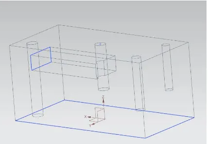
For the Analysis purpose an integrated model of the existing system in NX10.0 was designed so as to validate our ontological understandings of the execution process along with advantages, features and applications. DFM integrated application was analysed in NX10.0 environment by creating a simple 3D model which can be analysed for basic drilling rules used in manufacturing. The model created is shown in figure 4.
Figure 4. Sample CAD Model for DFM analysis
For analysis of the design for manufacturing drilling rules considered were: a) Deep Holes
b) Flat Bottom Holes
Figure 5. Analysis results on Sample Model.
The above rules analysed were in terms of ease in setting the standard requirements, time for execution, result generations, suggestions for modifications and specifying the region for modification. The analysis of the integrated model resulted in quick review of the modelled part in terms of manufacturing design standards. Though large and complex parts required some more time for execution, but is completely acceptable as very small and minor faults in design could be detected in complex parts easily. The integrating system also suggested the changes required with the region of interest. As the executions can be bifurcated at various modules and rule level which would emphasis on required check for analysis. Figure 5 shows the view in NX 10.0 after execution of the DFM plugin.
V. DFM INTEGRATED WITH CADFEATURE,ADVANTAGES AND APPLICATION
5.1. Features
Recognizes the problem region in the design model, as well as highlights it for better visuals and understanding in the Design model.
Solutions would be provided as a suggestion by the integrated system so as to address the relevant design issues.
The frame work would also analyse various generic rules required for manufacturing.
Design models are supported easily with respect to various native CAD formats as well as part files can be imported.
Manufacturing rule set implemented can be transferred and shared over the departments as well as to the suppliers.
This integration model can also be implemented with the product life cycle management or product data management and also for the various enterprise systems.
5.2 Advantages
Results in reduction of cost at the design level itself which also reduces the overall cost.
Measures would be taken for the previous misinterpretation, so as to ensure the non-repeatability by the fresh designers.
Skills gained by the designers can be recorded in the integration system.
Reduction in resultant time required from designing to manufacturing.
The integration model could contribute to the andragogy of engineers.
5.3 Application
Validate upstream manufacturability, identifying design areas which would be strenuous, costly or unendurable for manufacturing.
Design suggestions for manufacturing processes can be automated.
Provide a process for best practice knowledge capture and re-use for continuous improvement.
Provide a process for incremental development to acquire knowledge and its reusability.
Rework expenditure can be controlled.
VI. CONCLUSION
The contribution of this paper in understanding the integration process of DFM ontologies will here by give a clear idea of process flows in a cad integrated system.
Concluding the analysis of CAD Integrated DFM software i.e. DFM plugin shows that such kind of integration model is very advantageous for creating design in terms of manufacturing aspects and that too much easily than the conventional design for manufacturing.
Due to the existence of future scope the developmental work would contribute to a considerable extent for designers to recognize the rule which have failed in the design and by increasing the accuracy of detection by contributing to strong optimized logic and analysing the regression time for results.
REFERENCES
[1] Satyandra K. Gupta, William C. Regli “Integrating DFM with CAD through Design Critiquing” Concurrent Engineering: Research and Applications, Volume 2, Number 2.
[2] André Luiz Tietböhl Ramos and Michael P. Deisenroth “Ontologies in a DFM Framework” 19th International Conference on Production Research
[3] Bajaj M., Peak R., Wilson M., Kim I., Thurman T., Benda M., Jothishankar M.C., Ferreira P., Stori J., Towards Next-Generation Design for Manufacturability (DFM) Frameworks for Electronics Product Realization. Session 210, IEMT, Semicon West 2003, 2003.
[4] Sambu, Shiva Prasad, A Design for Manufacture Method for Rapid Prototyping and Rapid Tooling. PhD thesis, 2001. [5] Peter Wilson. A View of STEP, chapter Geometric Modeling for Product Realization, 1993, Elsevier Science Publishers.
[6] International Organization for Standardization ISO, 1995, TC184/SC4/WG7 Document N65 – Product Data Representation and Exchange Part 11: EXPRESS Language Reference Manual.
[7] International Organization for Standardization ISO, 1993, DIS 10303-21 Product Data Representation and Exchange Part 21: Implementation Methods, Clear Text Encoding of the Exchange Structure - Draft International Standard.
[8] International Organization for Standardization ISO, 1995, TC184/SC4/WG7 Document N394 – Product Data Representation and Exchange Part 24: Standard Data Access Interface - C Language Late Binding.
![Figure 1. Critiquing flow for integration architecture of DFM in CAD [1]](https://thumb-us.123doks.com/thumbv2/123dok_us/1601646.1197915/2.595.154.459.438.625/figure-critiquing-flow-integration-architecture-dfm-cad.webp)