Image Inpainting using Exemplar based and
FMM Algorithm
Neha R. Khairnar1, Dhanashri K. Khairnar2, Simran Kaur I. Birdi3, Pappukumar G. Yadav4
Lecturer, Dept of Computer Engineering, Guru Gobind Singh Polytechnic, Nashik, India1 Tech Asst, Dept of Computer Engineering, Guru Gobind Singh Polytechnic, Nashik, India2,3,4
ABSTRACT: Inpainting is the art of restoring lost parts of an image and reconstructing them based on the background
information. This has to be done in an undetectable way. This will be use for to remove the unwanted objects or unwanted data from the original image but this change is not noticeable by the user. Hence this will be done by using the two algorithms namely: Exampler Based Algorithm and Fast Marching Method. Digital Image Inpainting tries to imitate this process and perform the Inpainting automatically. Details that are hidden completely by the object to be removed cannot be recovered by any mathematical method. Such software has several uses. One use is in restoring photographs. Another use of Image Inpainting is in creating special effects by removing unwanted things from the image. Unwanted things may range from microphones, ropes, some unwanted person and logos, stamped dates and text etc. in the image. These parts can then be reconstructed using Image Inpainting. Natural images and photographs sometimes may contain stains or undesired objects covering significant portions of the images. The process of removing objects from images starts with mask out the undesired object, making the area where the object previously occupies a gap. Then the gap will be filled using graphical techniques. Among the graphical techniques that are used to fill the gap after object removal, two most commonly used are: Image Inpainting and texture synthesis. Exemplar based techniques, which cheaply and effectively generate new texture by sampling and copying color values from the source. Exemplar based algorithm is used for removing large objects from digital photographs. The Fast Marching Method (FMM) is used to remove all scratches within the image.
KEYWORDS: Exemplar based, Fast marching method.
I.INTRODUCTION
graphical techniques that are used to fill the gap after object removal, two most commonly used are: image inpainting and texture synthesis. Image inpainting refers to the process of changing an image so that the change is not noticeable by an observer. It is usually applied to the task of restoring damaged images and is considered an art for the careful artist's eye it takes to get all the details right.. Exemplar based techniques, which cheaply and effectively generate new texture by sampling and copying color values from the source. Exemplar based is used for removing large objects from digital photographs and replacing them with visually plausible backgrounds. The Fast Marching Method (FMM) is used to remove all scratches within the image. FMM algorithm is used for removing all scratches from digital photographs and replacing them with visually plausible backgrounds.
II.LITERATURE SURVEY
1.Image Inpainting by Kriging interpolation technique:
Kriging is a geostatistical interpolation method that takes into account both the distance and the degree of variation between known points when predicting values in unknown locations. Kriging is aiming to estimate unknown values at specific points in space by using data values from its surrounding regions Kriging predictions are treated as weighted linear combinations of the known locations. According to Kriging technique, the closer the input, the more positively correlated predictions. Now, let's bring the previously mentioned thoughts into digital image processing. According to, the pixels within the same k*k block are highly correlated, therefore; the application of Kriging inside the k*k block will yields high positively correlated predictions. Kriging gives weights for each point inside k*k block in accordance to its distance from the unknown value Actually, these predictions treated as weighted linear combinations of the known values. The contamination may be thin scratch, thick scratch, text, bad areas generated by aging, or even unwanted objects that may be eliminated from the original image. These contaminated areas will be marked according to its corresponding mask. After that, the k*k block will be dispatched to Kriging interpolation technique to predict the contaminated areas using the accurate prediction feature of Kriging Image.
2. Inpainting Using Cloning Algorithm:
In recovery from the damaged image cloning algorithms are used, in which the user specifies the co-ordinates for the area known as source domain. Damaged area is target domain. To interpolate the source domain with target domain seamlessly. cloning algorithms are used. Steps of algorithms:
1) Identify the co-ordinate of target domain.
2) Specify the approximate co-ordinates of source domain which is to be used for recovery. 3) Mask source domain and select the region of interest.
4) Apply cloning algorithms namely poisson editing, Multiscale transformation method, Shepard's method to get the seamless inpainted image.
3. Image Inpainting using TV based algorithm:
Image inpainting algorithm based on TV model is essentially a weighted-average algorithm. The smaller the difference between target-pixel and neighborhood pixels is, the greater weight is, on the contrast, the greater the difference is, the smaller the weight is. Iteration is in fact a process of anisotropic information diffusion. Experiments show that there are more non damaged pixels around damaged pixel ,then the speed of the diffusion is faster, which means the converged speed is faster and inpainting is also faster. Thus, this paper try to divide the damaged region of image into a number of layers, and then doing the inpainting layer by layer. However, there is still a problem that there are some pixels whose non -damaged neighborhood-pixels is less in each layer. At that moment, there will be more available information around the pixel, so information diffusion will be faster and stronger. However, the traditional image inpainting method based on TV model iteratively inpaint damaged pixels line by line, and it did not treat damaged region as a whole, which will inevitably result in the available information around damaged region has not been maximized.
III.SYSTEM ARCHITECTURE
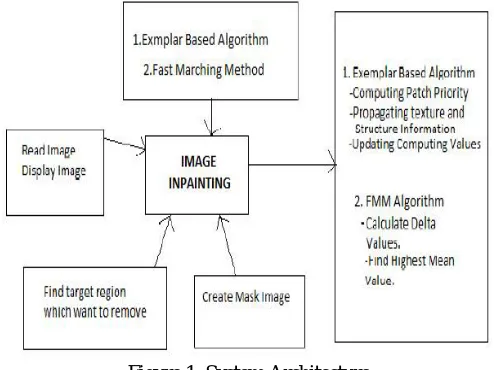
Software architecture alludes to the overall structure of the software and the ways in which that structure provide conceptual integrity for a system. In its simplest form, architecture is the hierarchical structure of the program components (modules), the manner in which these components interact, and the structure of the data that are used by the components. The primary objective of architectural design is to develop a modular program structure and represent the control relationships between modules. In addition, architectural design melds program structure and data structure, defining interfaces that enable data to follow throughout the program. The Architectural design of this work is presented in the following specification. Image to be filled is selected by the user. Find the edge by Means of canny algorithm. Find the target region to be filled. Process each pixel and find the patch that is to be filled by exemplar inpainting method. Find the Confidential term and Data term. Data term is found by Gradient Vector and Orthogonal Vector. Find the quadrant coefficient term and fill the region by appropriate color.
Figure 1. System Architecture
IV.EXEMPLARBASEDALGORITHM
Exemplar-based approaches perform well for two-dimensional textures. But, in addition, that exemplar-based texture synthesis is sufficient for propagating extended linear image structures. This algorithm is proposed for removing large objects from digital images. Exemplar-based texture synthesis contains the essential process required to replicate both texture and structure; the success of structure propagation, however, is highly dependent on the order in which the filling proceeds. As effective as these techniques are in replicating consistent texture, they have difficulty filling holes in photographs of real-world scenes, which often consist of linear structures and composite textures – multiple textures interacting spatially. The main problem is that boundaries between image regions are a complex product of mutual influences between different textures. Their drawback is that the diffusion process introduces some blur, which is noticeable when the algorithm is applied to fill larger regions. The algorithm presented here combines the strengths of both approaches. As with inpainting, we pay special attention to linear structures. But, linear structures abutting the target region only influence the fill order of what is at core an exemplar-based texture synthesis algorithm. The result is an algorithm that has the efficiency and qualitative performance of exemplar-based texture synthesis, but which also respects the image constraints imposed by surrounding linear structures. Our algorithm builds on very recent research along similar lines. The work in decomposes the original image into two components; one of which is processed by inpainting and the other by texture synthesis. The output image is the sum of the two processed components[2].
A related technique drove the fill order by the local shape of the target region, but did not seek to explicitly propagate linear structure. Finally, Zalesny et al. describe an interesting algorithm for the parallel synthesis of composite textures. They devise a special-purpose solution for the interface between two textures. In this paper we show that, in fact, only one mechanism is sufficient for the synthesis of both pure and composite textures[3].
The core of our algorithm is an isophote-driven image sampling process. It is well-understood that exemplar based approaches perform well for two-dimensional textures. But, we note in addition that exemplar based texture synthesis is sufficient for propagating extended linear image structures, as well. A separate synthesis mechanism is not required for handling isophotes. For ease of comparison, we adopt notation similar to that used in the inpainting literature. The region to be filled, i.e., the target region is indicated by Ω, and its contour is denoted ∂Ω. The contour evolves inward as the
algorithm progresses, and so we also refer to it as the “fill front”. The source region which remains fixed throughout the algorithm, provides samples used in the filling process. We now focus on a single iteration of the algorithm to show how structure and texture are adequately handled by exemplar-based synthesis. Suppose that the square template Ψp\εΩ
centered at the point p, is to be filled. The best-match sample from the source region comes from the patch (Ψ^)q, which is most similar to those parts that are already filled in Ψp. In the example in fig. 2b, we see that if Ψp lies on the
continuation of an image edge, the most likely best matches will lie along the same (or a similarly coloured) edge. All that is required to propagate the isophote inwards is a simple transfer of the pattern from the best-match source patch [2].
We now proceed with the details of our algorithm. First, a user selects a target region, Ω to be removed and filled. The source region, may be defined as the entire image minus the target region (k=I-Ω), as a dilated band around the target
region, or it may be manually specified by the user. Next, as with all exemplar-based texture synthesis, the size of the template window must be specified. We provide a default window size of 9*9 pixels, but in practice require the user to set it to be slightly larger than the largest distinguishable texture element, or “texel”, in the source region. Once these parameters are determined, the remainder of the region-filling process is completely automatic. In our algorithm, each pixel maintains a colour value (or “empty”, if the pixel is unfilled) and a confidence value, which reflects our confidence in the pixel value, and which is frozen once a pixel has been filled[3]. During the course of the algorithm, patches along the fill front are also given a temporary priority value, which determines the order in which they are filled. Then, our algorithm iterates the following three steps until all pixels have been filled:
1) Computing patch priorities
In this algorithm performs the synthesis task through a best-first filling strategy that depends entirely on the priority values that are assigned to each patch on the fill front. The priority computation is biased toward those patches which: (i) are on the continuation of strong edges and (ii) are surrounded by high-confidence pixels. Given a patch ΨP centered at the point p for some p є ɗΩ. We define its priority P(p) as the product of two terms:
P(p)= C(p).D(p)
C(p) is the confidence term and D(p) is the data term, and they are defined as follows:
Where |ΨP | is the area of ΨP, α is a normalization factor (e.g., α = 255 for a typical grey-level image), np is a unit vector
orthogonal to the front Ω in the point p and ┴ denotes the orthogonal operator. The priority P(p) is computed for every border patch, with distinct patches for each pixel on the boundary of the target region. During initialization, the function C(p) is set to I-Ω The confidence term C(p) may be thought of as a measure of the amount of reliable information surrounding the pixel p.
The intention is to fill first those patches which have more of their pixels already filled, with additional preference given to pixels that were filled early on (or that were never part of the target region). At a coarse level, the term C(p) of (1) approximately enforces the desirable concentric fill order. As filling proceeds, pixels in the outer layers of the target region will tend to be characterized by greater confidence values, and therefore be filled earlier; pixels in the centre of the target region will have lesser confidence values. The data term D(p) is a function of the strength of isophotes hitting the front Ω at each iteration.
This term boosts the priority of a patch that an isophote” flows” into. Broken lines tend to connect, thus realizing the “Connectivity Principle” of vision psychology [3].
(a) Original image, with the target region Ω, its contour ∂Ω and the source region clearly marked. (b) We want to synthesize the area delimited by the patch Ψp centred on the point p p€∂Ω. (c) The most likely candidate matches for
Ψp lie along the boundary between the two textures in the source region, e.g., Ψq’ and Ψq’’ . (d) The best matching patch in the candidates set has been copied into the position occupied by Ψp, thus achieving partial filling of Ω. The target region Ω has, now, shrank and its front has assumed a different shape. See text for details.
2) Propagating texture and structure information:
Once all priorities on the fill front have been computed, the patch ΨP with highest priority is found. We then fill it with
data extracted from the source region Φ. In traditional inpainting techniques, pixel-value information is propagated via diffusion. As noted previously, diffusion necessarily leads to image smoothing, which results in blurry fill-in, especially of large regions. On the contrary, we propagate image texture by direct sampling of the source region. We search in the source region for that patch which is most similar to formally,
ψ_(q ) =arg (min)┬(φ_qεΦ ) d(φ_p Φ ,φ_q )
Where the distance d(ψa,ψb) between two generic patches and ψa and ψb is simply defined as the sum of squared differences (SSD) of the already filled pixels in the two patches Having found the source exemplar ψq, the value of each
pixel-to-be-filled, p’ ,|p’єψp∩Ω is copied from its corresponding position inside ψˆq. This suffices to achieve the
propagation of both structure and texture information from the source Φ to the target region Ω, one patch at a time (cf.,
fig. 3.10d). In fact, we note that any further manipulation of the pixel values (e.g., adding noise, smoothing etc.) that does not explicitly depend upon statistics of the source region, is more likely to degrade visual similarity between the filled region and the source region, than to improve it[3].
3) Updating confidence values:
After the patch ψˆp has been filled with new pixel values, the confidence C(p) is updated in the area delimited by ψˆp as follows:
C(P)=C(P ˆ ) ∀_(P )\ε φ(P∩) ˆψ
This simple update rule allows us to measure the relative confidence of patches on the fill front, without image-specific parameters. As filling proceeds, confidence values decay, indicating that we are less sure of the color values of pixels near the centre of the target region. A pseudo-code description of the algorithmic steps is shown in table I. The superscript t indicates the current iteration[3].
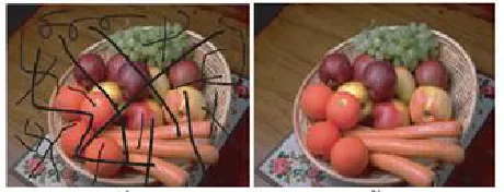
Example:
Figure 3. Example of exemplar based algorithm
V.FAST MARCHING METHOD
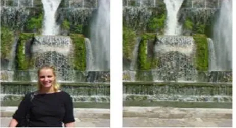
attempt to continue the isophotes (lines of equal gray value) as smoothly as possible inside the reconstructed region. In other words, the missing region should be inpainted so that the inpainted gray value and gradient extrapolate the gray value and gradient outside this region. Several inpainting methods are based on the above ideas. The Total Variational (TV) model uses an Euler-Lagrange equation coupled with anisotropic diffusion to maintain the isophotes’ directions. The Curvature-Driven Diffusion (CCD) model enhances the TV method to drive diffusion along the isophotes’ directions and thus allows inpainting of thicker regions. All above methods essentially solve a Partial Differential Equation (PDE) that describes the color propagation inside the missing region, subject to various heuristics that attempt to preserve the isophotes’ directions. Preserving isophotes is, however desirable, never perfectly attained in practice. The main problem is that both isophote estimation and information propagation are subject to numerical diffusion. Diffusion is desirable as it stabilizes the PDEs to be solved, but leads inevitably to a cetain amount of blurring of the inpainted area. A second type of methods repeatedly convolves a simple 3 × 3 filter over the missing regions to diffuse known image information to the missing pixels. However impressive, the above methods have several drawbacks that preclude their use in practice. The PDE-based methods require implementing nontrivial iterative numerical methods and techniques, such as anisotropic diffusion and multiresolution schemes. Little or no information is given on practical implementation details such as various thresholds or discretization methods, although some steps are mentioned as numerically unstable. Moreover, such methods are quite slow, e.g., a few minutes for the relatively small inpainting region shown in Figure 1. In contrast, the convolution-based method described in is fast and simple to implement. However, this method has no provisions for preserving the isophotes’ directions. High-gradient image areas must be selected manually before inpainting and treated separately so as not to be blurred. We propose a new inpainting algorithm based on propagating an image smoothness estimator along the image gradient, similar to. We estimate the image smoothness as a weighted average over a known image neighborhood of the pixel to inpaint. We treat the missing regions as level sets and use the fast marching method (FMM) described in to propagate the image information. Our approach has several advantages [1]. It is very simple to implement (the complete pseudo code is given here). It is considerably faster than other inpainting methods–processing an 800×600 image (Figure 1) takes under three seconds on a 800 MHz PC. It produces very similar results as compared to the other methods it can easily be customized to use different local Inpainting strategies[1].
Figure 4. Image inpainting using FMM
VI.CONCLUSION
In this way we studied the two algorithm namely Exampler Based Algorithm and FMM algorithm. We have referred IEEE reference papers and books related to image processing from which we have got the guide-lines. This will be implemented in future and it is benefit to users.
REFERENCES
[1] [Alexandru Telea] , Eindhoven University of technology, “An Image Inpainting Technique based on Fast Marching Method “,2003.
[2] [Yan-Ran, Lixin Shen and Bruce W.Suter] , Senior Member ,” Adaptive inpainting Algorithm Based on DCT”,IEEE Vol 22,No 2, February 2013. [3] [A.Criminisi, P.Perez, K.Toyama],”Object Removal By Exemplar Based In Painting ”, IEEE 2003.