An Efficient and Low–Cost Design
Methodology for Mitigation of Multiple Error
Recovery in TMR System
H R Vanishree 1, B M Raksha 2, Hamsaveni N3
P.G. Student, Department of Electronics and Communication Engineering, SJB Institute of Technology, Bengaluru,
Karnataka, India1, 2
Associate Professor, Department of Electronics and Communication Engineering, SJB Institute of Technology,
Bengaluru, Karnataka, India3
ABSTRACT: In this paper, we present a scan-chain-based multiple error recovery technique for triple modular redundancy (TMR) systems (SMERTMR). The proposed technique reuses scan-chain flip-flops fabricated for testability purposes to detect and correct faulty modules in the presence of single or multiple transient faults. In the proposed technique, the manifested errors are detected at the modules’ outputs, while the latent faults are detected by comparing the internal states of the TMR modules. Upon detection of any mismatch, the faulty modules are located and the state of a fault-free module is copied into the faulty modules. In case of detecting a permanent fault, the system is degraded to a master/checker configuration by disregarding the faulty module. FPGA-based fault injection experiments reveal that SMERTMR has the error detection and recovery coverage of 100% and 99.7% in the presence of single and two faulty modules, respectively, while imposing negligible area and performance overheads on the traditional TMR systems.
KEYWORDS: Fault-tolerant designs, roll-forward error recovery, scan chain, triple modular redundancy (TMR).
I. INTRODUCTION
Today, the use of embedded systems in safety-critical applications such as avionics, process control, and patient life-support monitoring has become a common trend. Many real-time computing systems are used under remote circumstances, such as in nuclear power plants, aircraft, and spacecraft. In these environments, computing systems are highly susceptible to errors due to radiation. Maintenance and repair is usually very expensive and time-consuming for these applications. Such a system often has both timing constraints and fault-tolerance requirements. To meet the reliability requirement, such embedded systems should be equipped with appropriate error detection and correction mechanisms. However, achieving a high level of reliability and meeting the timing requirements are conflicting objectives, i.e., the reliability enhancement may have a negative impact on timing constraints. The general idea for achieving error detection and correction is to add some redundancy (i.e., some extra data) to a message, which receivers can use to check consistency of the delivered message, and to recover data determined to be corrupted. For example, in a rollback recovery-based system, the overall reliability is improved; however, since the expected response time increases, the probability of missing deadlines also increases for certain applications.
Generally, improving system reliability without considering its real-time constraints is not justifiable for safety-critical applications. Consequently, providing fault-tolerant techniques with minimum performance overhead in embedded processors is of decisive importance.
In this project, a scan-chain-based roll-forward error recovery technique for TMR-based systems is presented, which addresses the shortcomings of ScTMR. The proposed technique, called scan chain-based multiple error recovery TMR (SMERTMR), has the ability to locate and remove latent faults in TMR modules as well as to recover the system from multiple faults affecting two TMR modules. To the best of my knowledge, SMERTMR is the first roll-forward error recovery technique for a TMR-based system that has the capability of error recovery in the presence of multiple latent faults as well as two faulty modules. The main idea behind SMERTMR is to reuse the available scan chains devoted for testability purposes in order to compare the internal states of TMR modules to locate and restore the correct state of faulty modules using the state of non faulty modules. Nevertheless, the offline testability characteristics of the system are preserved.
As compared to other TMR-based recovery techniques, SMERTMR has negligible area overhead, as it reuses the available resources within the circuit.The main design objective of the proposed work is to design a voter circuit. Then design an SMERTMR in comparison mode and SMERTMR in recovery mode. Then combine these two modes in a single unit. This technique detects, locates, and corrects multiple faults affecting single and two faulty modules. The results also show that the area and the performance overheads are less.
II. RELATEDWORK
Traditional TMR voter circuit masks the faults which are affecting only one module, and the faulty module cannot be recovered in a traditional TMR system, because the system was unable to identify the faulty module. The techniques which are presented in [1], [2-5], and [6] uses modified voters to detect the faulty module. The voters which are presented in [1], [2-5] and [7] are hardware based, while the techniques presented in [8] uses a pure software based method to detect faults and voting diagnosis resulting in negative impact on the system performance. Many voters proposed in [1], [2-5], [8], [9] keeps the record of the faulty modules and whenever the count exceeds a predefined number, then this error is considered as permanent error.
Another method to facilitate fault resistant in real-time systems is through redundancy, like duplex pairs or N-modular redundancy (NMR). An NMR system duplicates a computing module into N number of modules and runs all in parallel and later it uses voter circuit to mask errors at outputs. Hence, NMR circuits are able to successfully resist faults as long as they happen in no more than [N/2] modules. The duplex-pair system uses double pairs of duplicated modules, which means four in total, for fault resistance [9].
The other way to maintain and restore the correct states of the system is through re-computation, which is well known method called rollback recovery [14]. In this system which is also called a checkpoint, whenever error occurs and is selected during operation, the system will maintain and restore its state back to the previous checkpoint and starts re-computation from the start. The drawback of this system is it consumes lot of computation time.
The first shortcoming is protecting a circuit which includes N number of flip-flops by using such voter circuit scheme causes significant area overhead to the circuit. Second, placing a voter circuit right after each flip-flop will result in increasing the delay of the critical path in the circuit, which in turn may lead to increasing performance overhead. Third the combinational logic which is used for voter placement circuit leads to increase in susceptibility of the system to single-event transients.
Another method for detecting permanent faults in TMR systems using the spare modules has been presented in [21]. Here all the possible combination of the three modules is tested to find the faulty module. The other technique for detecting permanent faults has been proposed in[22] called the dual modular redundancy (DMR).Here in this technique, every module in the system runs in the DMR mode along with the spare for a small duration in order to detect possible permanent faults.
The other method to determine and handle permanent faults in TMR systems is Detect–diagnose–reconfigure. In this method, if a permanent error is detected, then the system will detect the faulty module and will replace it with a extra spare module. But this method cannot be used without a spare module. There are also various methods which suggests the protection of a system at the circuit level .The Dual Interlocked storage Cell (DICE) is a circuit-level design which has the capability to detect and recover transient faults at any of its feedback nodes.
An efficient error correction system needs to be designed to protect a memory of every element in the reconfigurable DSP chip. System-level schemes rely on components outside of the memory structure to perform calculations and correct errors that may be present in the memory. Circuit-level schemes exist entirely inside of the memory structure, meaning that fault- tolerance is incorporated directly into the design of the RAM latches. There are four of major schemes for this purpose. Cross-parity, Hamming code, and Triple Modular Redundancy (TMR) are system-level schemes, while the Dual-Interlocked storage Cell (DICE) approach is a circuit-level scheme.
Error detection and correction in the cross parity scheme is made possible by the storage of a parity bit for every row and column in a memory unit [1]. These parity bits are generated during writes to the memory. When a write occurs to the location corresponding to row i and column j of the memory, parity bits for i and j must be updated. If the same memory location is read at a later time, then the current parity of row i and column j is compared to the stored parity of i and j.
Figure 1 illustrates the relationship between the parity bits and the rows and columns of the data memory. If the current parity is not consistent with the stored parity, then the memory location in question contains an incorrect bit (assuming there is no more than one error in the system). If this is not the case, then the bit is determined to be correct. The Hamming code approach divides the memory into multiple data words, and provides the ability to correct up to one error at a time in each data word. Encoded priority bits are inserted into these data words. An example of an 8-bit data word with four inserted Hamming parity bits is shown in Figure 2.
During a read operation, this encoded priority is decoded to give the position of an erroneous bit in the data word, if one exists. Accomplishing this requires an extensive XOR network to calculate the encoded priority, and a dedicated decoder to determine the position of the incorrect bit. In contrast, cross-parity requires a much smaller XOR capability, and no dedicated decoder. Because of this, it is obvious that the cross-parity is more optimal in terms of both size and computational complexity. Therefore, Hamming code was ruled out for this project.
III. ARCHITECTUREOFPROPOSEDSMERTMRSYSTEM
The ScTMR technique introduced in the previous section can recover from a transient fault only if it manifests in the module outputs. This is because only modules outputs are compared by the voter.
As will be shown in the experimental results, it is quite likely that a fault remains latent in a module for a long time without propagating to the module outputs. During this period, it is likely that a second fault occurs in the other modules, resulting in an unrecoverable condition.
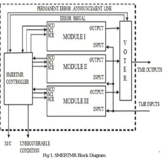
Fig 1. SMERTMR Block Diagram.
Figure 1 shows the SMERTMR block diagram. As shown in this figure, the SMERTMR architecture consists of three redundant modules, a voter and a SMERTMR controller.
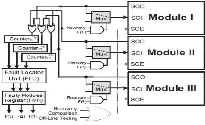
Fig 2. SMERTMR in Comparison Mode
Figure 2 shows a simplified block diagram of the SMERTMR controller circuit working in the comparison mode. In this mode, the internal states of all TMR modules are shifted out using the scan chains and all module pairs (I/II, I/III, and II/III) are compared. As shown in Figure 2, there are three counters, namely, Counter_12,Counter_13, andCounter_23, to store the number of mismatches between each module pairs.
Basically, the system may be in the following four situations.
1) All modules are fault-free: In this case, all three counters will be equal to zero.
2) There is only one faulty module: Let us assume that module i is faulty and it contains x erroneous flip-flops
and the other modules, i.e., modules j and k are fault-free. In this case, we will have Counter_ij = Counter_ik = x. Note that, since both modules j and k are fault-free, counter jk will be equal to zero (i.e., Counter_jk = 0). After extracting the number of mismatches, the system enters the recovery mode and the state of module i is recovered using the state of either modules j or k.
3) There are two faulty modules: Suppose that there are two faulty modules (e.g., modules i and j ) and one
fault-free module (here, module k). Let A and B be the sets of erroneous flip-flops in modules i and j , respectively.
Here, the faulty modules may have either no common erroneous flip-flops (A ∩ B = Ø) or at least one
common erroneous flip-flop (A ∩ B ≠ Ø). Assume that the number of erroneous flip-flops in modules i and j
are denoted with x and y, respectively. In case A ∩ B = Ø, Counter_ik= x, Counter_jk = y, and Counter_ij= x
+ y.
4) All modules are faulty: In this case, SMERTMR is not able to locate the faulty modules and it enters the
unrecoverable condition.
In the SMERTMR technique, upon completion of the comparison mode, the fault locater unit (FLU) will determine the faulty modules.
Fig 3. SMERTMR in Recovery Mode
Figure 3 shows a simplified block diagram of the SMERTMR controller circuit in the recovery mode. In this mode, the SMERTMR controller enables the scan chains of the SMERTMR modules and configures the multiplexers as follows:
The SCI signal of fault-free modules is connected to the SCO signal of the same module. In addition, the SCI signal of the faulty module is connected to the SCO of one of the fault-free modules. As shown in Figure 3, the value of the FMR register is used in the recovery mode to select the incoming driver of the appropriate signal driver for the SCI signals. Using the configuration shown in Figure 3, the state of one of the fault-free modules is copied into the faulty modules after L_SC clock cycles.
While shifting out the states of the modules in the recovery mode, similar to the comparison mode, they are also compared to find any mismatch due to faults occurring in the recovery process. During the recovery process, whenever a mismatch is detected, the corresponding counter value containing the number of mismatches is decreased by one unit. At the end of the recovery process, all counters should be zero.
Permanent error detection in SMERTMR is similar to that in the ScTMR technique. SMERTMR employs two internal registers named most recent faulty module (MRFM) and number of consecutive faults (NCF). MRFM holds the faulty module number detected most recently.
IV. SIMULATIONRESULTS
The design has been coded by Verilog HDL.All the results are synthesized and simulated using Xilinx are shown in figure.
Fig 4. Simulation results in comparison mode
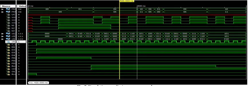
Figure 5 displays the simulation results in recovery mode. Here whenever the counter detects the error in the module it enters to the recovery mode. Here the state of the fault fee module is compared with the states of the faulty modules and the state of faulty module is replaced by the state of the fault free module.
Fig 5 Simulation results in recovery mode
Fig 6. Simulation result of SMERTMR system
V. CONCLUSION AND FUTURE WORK
In this project, a roll-forward technique, called SMERTMR is presented, to recover multiple errors in TMR systems. In the proposed technique, a built-in design for testability resources available in digital circuits to recover faulty modules in the presence of multiple transient faults is employed. The fault injection experiment demonstrated that SMERTMR detects, locates, and corrects 100% and 99.7% of multiple faults affecting single and two faulty modules, respectively. The results also show that the area and the performance overheads of SMERTMR, as compared to the traditional ScTMR system, are less than 3% and 1%, respectively. An analytical assessment also demonstrated that SMERTMR improves the reliability of TMR systems by several orders of magnitude compared to the state-of-the-art techniques.
Five Modular Redundancy (FMR) is the technique to duplicate the same module to five times. The system still has correct resulted since the modules are having correct result with at least three modules, when the error is happening in the two modules the system can still tolerance to such error. Using Dynamic Partial Reconfiguration (DPR) will not interrupt the system which is running, therefore mitigation to the error module can be done without disturbing the system. DPR can be done very fast and low power consumption because we only reconfigure to the partial area of an FPGA.
REFERENCES
1. Bartlett, J. F., Tandem Computers Inc., Cupertino, CA, “A Nonstop Operating System,” Proc. of the 11thHawaii Int’l Conf on System Sciences,
pp. 103- 1 17, 1978.
9. M. Ebrahimi, S. G. Miremadi, H. Asadi, and M. Fazeli, “Low-Cost Scan-Chain-Based Technique to Recover Multiple Errors in TMR Systems,” IEEE Trans. Very Large Scale Integr. (VLSI) Syst., vol. 21, no. 8, pp. 1454–1468, Aug. 2013.