EXPERIMENTAL VALIDATION OF THE MATERIAL PROPERTIES
OF THE INNER CONTAINMENT OF THE
PRESSURIZED WATER REACTOR (EPR
TMTYPE)
Dirk Ostermann1, Christian Krumb1 and Burkhard Wienand1
1
Areva GmbH, Kaiserleistraße 29, 63067 Offenbach, Germany
ABSTRACT
The containment of the pressurized water reactor (EPRTM type) consists of an outer containment to protect the reactor building against external hazards (such as airplane crash) and of an inner containment that is subjected to internal overpressure and high temperature in case of internal accidents. The current paper gives an overview of the most important tests that have been carried out during the design phase of the inner containment in order to verify the properties of applied materials and consolidate the input for detail design calculations.
1. INTRODUCTION
The pressurized water reactor (EPRTM type) is a generation 3+ reactor. Currently, four EPRTM reactors are in the construction phase, one in Finland, one in France and two in China. The current paper gives an overview of the experimental validation of the material properties of the inner containment.
2. OVERVIEW OVER THE CONTAINMENT OF THE PRESSURIZED WATER REACTOR (EPRTM TYPE)
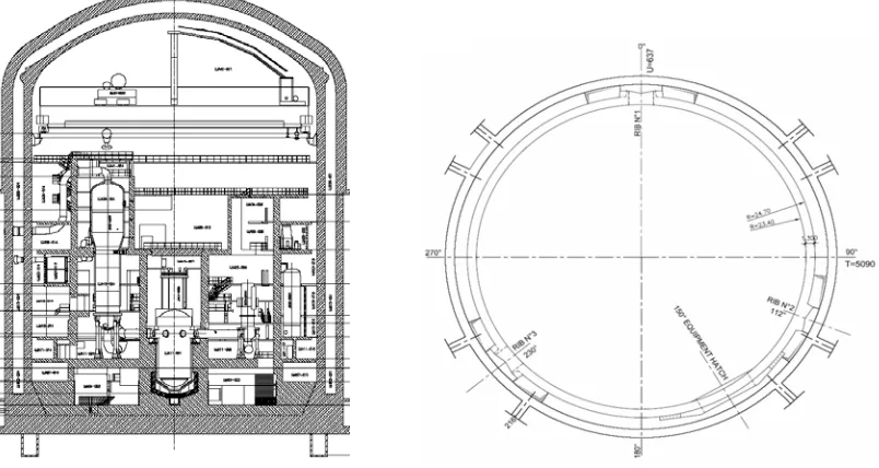
The containment of the EPRTM reactor consists of an outer containment and an inner containment, see Figure 1. The outer containment shell is a reinforced concrete structure with high wall thickness and protects the inner containment from direct effects of external hazards, such as airplane crash (APC) and explosion waves.
The inner containment is a pre-stressed concrete structure, designed to bear loads from
internal hazards, such as overpressure and high temperature resulting from Loss of Coolant
Accident (LOCA). The leak tightness function is ensured by a steel liner on the inner surface of
the containment that is anchored in the inner containment wall by L-profiles (so-called
“continuous anchors”) and by headed studs. For more details on the containment of the
pressurized water reactor (EPR
TMtype) see Ostermann, D., Wienand, B., Krumb, C. (2012).
3. EXPERIMENTAL VALIDATION OF THE MATERIAL PROPERTIES
In order to get a verified basis for the material properties several extensive test programs have been performed within the framework of the Olkiluoto 3 project in cooperation with different universities, research institutions and material testing institutes. All these tests have been carried out under supervision of independent third party inspectors.
The results of the tests serve as input values for the Finite Element calculations (e.g. determination of the stiffness of the supports). In addition, the test results give the basis for the determination of allowable loads and deformations.
3.1 Tests on Concrete
The tests on concrete specimens included the measurement of the concrete strength and the modulus of elasticity for fresh and hardened concrete. Furthermore, a creep and shrinkage test program was carried out.
3.2 Tests on Pre-stressing System
For the pre-stressing steel tests of the isothermal stress relaxation and deflected tensile tests have been performed. In addition, mock-up tests for the grout injection in deviated tendons have been carried out to avoid air vents in the tendon ducts. With these tests the injection procedure, including grout mixture, injection pressure, injection velocity and air venting could be verified. Figure 2 shows three deviated tendons and the hardened grout in a tendon duct after the test.
3.3 Tests on Liner Plates
The steel of the containment liner has been tested in uniaxial and biaxial tension tests in order to obtain the stress strain diagrams up to fracture. Figure 3 shows two of these test specimens (one for the uniaxial tension test and one for the biaxial tension test). These tests have been carried out on test specimens with weld and without weld.
Figure 3: Test specimens for uniaxial tension test (left picture) and for biaxial tension test (right picture)
Figure 4 shows the stress-strain diagrams for one of the uniaxial tests for a specimen manufactured from the liner plate without weld and for a test specimen consisting of the liner weld. All test specimens were manufactured from original liner plates used for the construction site in Finland.
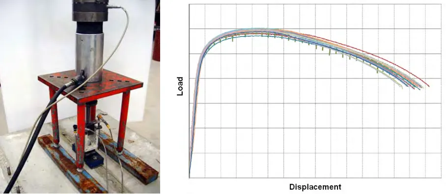
In addition, bending tests on welded test specimens have been carried out, see Figure 5. These tests showed the high ductility of the material. A bending of almost 180° was possible without fracture of the test specimens.
Figure 5: Bending test (left picture) and test specimens after bending (right picture)
3.4 Tests on Continuous Anchors
The liner is divided into liner fields by continuous anchors (L-profiles). These liner fields have different sizes. The largest liner field has a height of 1830mm and a width of 766mm. The liner is anchored into the inner containment wall by these L-profiles.
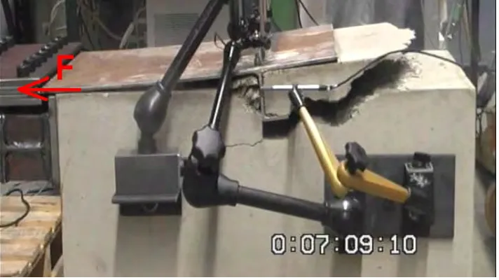
Continuous anchors (L-profiles) have been tested in order to find out the stiffness of these anchorages, the load bearing capacity, the ultimate displacement and the force-displacement diagrams. The tests have been carried out in pre-stressed concrete and in non pre-stressed concrete. Figure 6 shows one of the test specimens after fracture. The test shows a good correlation to the failure mode that was predicted by a Finite Element calculation (see Figure 7).
Figure 7: Predicted failure mode from a Finite Element analysis
3.4 Tests on Headed Studs
In addition to the continuous anchors the liner is also anchored to the inner containment wall by headed studs in a distance of 150mm. For these headed studs and extensive test program has been performed in order to find out the load bearing capacity, the ultimate displacement and the displacement diagrams. The tests have been carried out displacement controlled so that the load-displacement behavior could be obtained up to fracture.
The tests have been carried out as pure tension tests, as pure shear tests and also as a combination of tension and shear, so that the interaction relation between tension and shear could be verified. For this purpose obliged tension tests with an angle of 30° and 60° have been carried out. Figure 8 shows one of the tension tests on headed studs and the corresponding load displacement diagrams for the respective test series.
4. CONCLUSIONS
All relevant material parameters of the inner containment of the pressurized water reactor (EPRTM type) have been validated experimentally and supported the detail design phase by determining the allowable loads and deformations and served as input for theoretical evaluations. This included the material strength, the deformation capacity, the modulus of elasticity and the long time behavior of the materials that have been used. This extensive test program exceeded the test programs that are commonly carried out for new build projects and is unique for the construction of a nuclear power plant. It is the basis for the high safety standard of the pressurized water reactor (EPRTM type).
REFERENCES