18th International Conference on Structural Mechanics in Reactor Technology (SMiRT 18) Beijing, China, August 7-12, 2005 SMiRT18-S03-6
DYNAMICS OF MSR
Jiri Krepel
Forschungszentrum Rossendorf
Institute of Safety Research
P.O. Box 51 01 19
01314 Dresden, Germany
Phone:
+49 351 260 2537
Fax: +49 351 260 3440
E-mail:[email protected]
Ulrich Grundmann
Forschungszentrum Rossendorf
Institute of Safety Research
Dresden, Germany
Phone:
+49 351 260 3027
Fax: +49 351 260 3440
E-mail: [email protected]
Ulrich Rohde
Forschungszentrum Rossendorf
Institute of Safety Research
Dresden, Germany
Phone:
+49 351 260 2040
Fax: +49 351 260 3440
E-mail: [email protected]
Frank-Peter Weiss
Forschungszentrum Rossendorf
Institute of Safety Research
Dresden, Germany
Phone:
+49 351 260 3480
Fax: +49 351 260 3440
E-mail:[email protected]
ABSTRACT
The Dynamics of the Molten Salt Reactor (MSR) - one of the 'Generation IV' concepts - was studied by means of a code developed at FZR. The graphite-moderated channel type MSR was selected for the numerical simulation of the reactor with liquid fuel. The MSR dynamics is very specific because the fuel flow influences the delayed neutrons distribution. Presently, there are only a few accessible numerical codes appropriate for the MSR simulation, therefore the DYN3D-MSR code was developed based on the FZR in-house LWR code DYN3D. It allows the 3D transient simulating of neutronics in combination with parallel channel type thermal-hydraulics. By means of DYN3D-MSR, several transients typical for the liquid fuel system were analyzed. Those transients were initiated by reactivity insertion, by overcooling of fuel at the core inlet, by the fuel pump start-up or coast-down, or by the blockage of selected fuel channels.
1. INTRODUCTION
The first projects for reactors with liquid fuel go back to the pioneers’ time of nuclear energy, when various designs with different fuel-type have been proposed. From those the Molten Salt Reactor (MSR) could be considered as the most developed project [1]. The research on MSR was performed mainly in the Oak Ridge National Laboratory (ORNL), where the Molten Salt Reactor Experiment (MSRE) was realized in the sixties. This experiment has shown that the molten salt technology beside the energy production offers three main advantages:
1) excellent neutron economy,
2) continuous or in-batch reprocessing, 3) inherent safety features.
These three advantages make the MSR attractive also for the present Generation IV (GIF) initiative [2]. The aim of the GIF initiative is the development of technologies that achieve safety performance, waste reduction, and proliferation resistance while providing a nuclear energy option that is economically competitive. The MSR is studied also for spent fuel partitioning and transmutation (P&T) purposes. It is the aim of P&T to separate the different components of spent fuel (partitioning) and to reduce the radiotoxicity, mainly by the transmutation of actinides. A critical MSR can serve as transmutor with acceptable burning rates. The time period the radiotoxic inventory needs to reach the level of uranium ore can be shortened by transmutation from millions of years to less than one thousand years. Within the GIF initiative
the graphite-moderated channel type MSR based on the previous ORNL research is considered (Fig. 1). In this MSR, the mixture of molten fluoride salts circulates through the whole primary circuit acting as fuel and coolant simultaneously. The fuel, in the form of uranium tetra fluoride, is dissolved in the carrier salt. The core is formed from hexagonal graphite blocks each with a central fuel channel (see Fig.2). The liquid fuel causes two physical peculiarities: the fission energy is released predominantly directly into the liquid fuel and the delayed neutrons (DN) precursors are convected (drifted) by the fuel flow out of the core. Therefore, specific tools are needed for the reactor dynamics
analysis of the MSR.
Fig. 1: Scheme of MSR [2].
Consideration of the MSR within the GIF initiative and in the EU-project MOST (Review of Molten Salt Technology) in which we participated was the motivation to develop DYN3D-MSR for MSR dynamics simulation at the Institute of Safety Research. The code DYN3D-MSR [3] is based on the FZR in-house code DYN3D [4] which was developed and validated initially for LWR applications. Worldwide, only one comparable 3D code is presently suitable for the spatial numerical simulation of MSR dynamics.
2. NEUTRONICS OF THE MSR
The following set of equations is solved in each node n:
( )
( )
( ) ( )
(
)
( ) ( )
( )
( )
, , 1 1 , , , 1 2 1 , 1 1 11 t zt C zt S z
k t z t t z J t v t z n ext M j n j n j g n g n g f n g eff n n r n n n + + Φ Σ − = Φ Σ + ∇ + ∂ Φ ∂
∑
∑
= = λ νβ ; (1)
( )
( )
( ) ( )
( ) ( )
; , , , , 1 2 2 22 J zt t zt t zt
t v
t
z n n
s n n a n n n Φ Σ = Φ Σ + ∇ + ∂ Φ
∂ (2)
(
v ( ,))
1 ( , ) ( , ); ),
( 2
1 ,
, zt C zt
k t z C z t t z C n j n j g n g n g f n j g eff n j n n
j = β νΣ Φ −λ
∂ ∂ + ∂ ∂
∑
= (3)standard notation is used. Assuming constant drift velocity within one node and during one time step the equation (3) can be integrated in each node. These nodal solutions are combined with the method of characteristics to find the precursors distribution in the whole primary circuit. This method involves a tracking of fictitious fluid particle during one time step ∆t on its way through one or more nodes. The particle which trajectory ends on the outgoing edge of given node is selected. Once the starting point of the trajectory is found the initial precursors’ concentration is found by the linear interpolation between two edge values, which are known from the pervious time step. In next the known nodal solutions relevant for the trajectory position are sequentially used to find the precursors concentration on the end of the trajectory. To obtain the overall precursors distribution this procedure is used for every node.
As a consequence of the drift, the DN precursors propagate through the entire primary circuit (see Fig. 2). Nevertheless, the final effect on the neutron-kinetics depends mainly on the flow velocity and on the volumetric fuel proportion in the core and in the primary circuit, respectively.
0 5 10 15 20 25 30 35 40
Axial position [node]
0 0.2 0.4 0.6 0.8 Rel. delayed neutronsλiCi
0 0.4 0.8 1.2 1.6 Normalized power Nuclear power All delayed neutrons Group 1: 5% ß ( = 0.0127 s ) Group 2: 26% ß ( = 0.032 s ) Group 3: 22% ß ( = 0.128 s ) Group 4: 34% ß ( = 0.304 s ) Group 5: 10% ß ( = 1.349 s ) Group 6: 3% ß ( = 3.629 s )
λ λ λ λ λ λ -1 core -1 -1 -1 -1 -1
Fig. 2: Distribution of relative reactor power and 6 delayed neutrons groups for a salt
velocity of v=1m/s. The core and the external loop consist each from 20 axial nodes.
3. THERMAL-HYDRAULICS OF THE MSR
The thermal-hydraulics of DYN3D-MSR is based on the DYN3D light water reactor model [7]. However, the energy balance equation must be adapted for the liquid fuel. As mentioned above, it is a unique feature of the MSR reactors that the liquid molten salt is flowing through the core and the whole primary circuit acting as fuel and coolant simultaneously. The energy from fission is predominantly released directly in the fuel and is immediately convected by the flow out of the core, while the graphite is heated-up by the gamma and neutron radiation [8]. Thus the energy balance equation will include three energy sources:
( ) (
vh)
Qfission Qdelay Qgraphite,z h
t ∂ = + +
∂ + ∂
∂ ρ ρ (4)
standard notation is used. The three sources represent the direct heat release Qfission, the decay heat Qdelay, and the
heat exchange between graphite and salt Qgraphite. The heat source Qgraphite is defined by heat release and heat
analytical solution of the heat conduction equation must be known in the graphite. Thus, the hexagonal graphite blocks were approximated by cylinders with an inner fuel channel and divided into segments.
When all the three sources are known, the equation (4) can be integrated in each node using the same assumption of constant drift velocity as mentioned in the previous chapter. Once the solution in each node is known, the method of characteristics can be used to get the overall temperature distributions. As an example, typical axial temperature distributions in one fuel element divided into 20 axial nodes and 4 radial graphite segments are shown in Fig. 3.
2 4 6 8 10 12 14 16 18 20
Axial position [node] 520
560 600 640 680 720 760
Te
m
per
at
ur
e
[
oC]
Fuel Graphite: inner boundary outer boundary averaged
Fig. 3: Axial distributions of temperature in the MSR fuel channel. Inlet temperature of the
fuel is 550°C. Flowing through the core; it is heated up by 150°C, approximately.
4. MOLTEN SALT REACTOR EXPERIMENT
The Molten Salt Reactor Experiment – MSRE was an 8-MW, fluid-fuelled test reactor that operated from 1965 through 1969 in the Oak Ridge National Laboratory – ORNL [9]. The fuel consisted of a mixture of lithium, beryllium, and zirconium fluoride salts, to which uranium was added as UF4. The molten salt mixture with the
temperature above 600°C circulated through the reactor vessel, fuel pump, heat exchanger, and piping. These components have been constructed from Hastelloy-N (70%Ni, 18%Mo, 7%Cr, 5%Fe). The MSRE core consisted from square graphite stringers, which form the fuel channels. The original geometry can be seen from Fig. 4.
5. MSRE NODALIZATION
The MSRE core consisted form 610 square graphite stringers. The inner core diameter was 135 cm and the outer pressure vessel diameter was 142 cm. The width of each stringer was 5 cm and the inner core radius was filled by 577 full stringers. The remaining 33 elements were partly cut to fit into the cylindrical vessel (see Fig. 5). By this structure 1150 fuel channels were formed in the core. Through these channels the liquid fuel circulates by the rate 52 l/s. It corresponds to the drifting velocity of 19.7 cm/s. The nominal fuel pressure was 344.7 kPa and the nominal inlet and outlet temperature was 635°C and 663°C, respectively.
Graphite Fuel Salt
Hastelloy-N
Control Rods
Sample Pieces
Fig. 5: Structure of the MSRE core with detailed view of the central part.
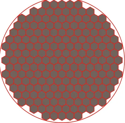
The code DYN3D-MSR is able to calculate with both Cartesian and hexagonal fuel assembly geometry. To reduce the calculating time the core was approximated with only about 200 channels while neglecting the central part construction and the control rods. The best approximation was obtained for hexagonal assembly geometry using only 199 channels (see Fig. 6). Along the axial direction, the core was divided into the 20 nodes. From those, 18 nodes represent the graphite-salt area. The graphite stringers were 166cm long, thus each from these 18 nodes was 9.2cm long. The first and the last node represent the upper and lower plena, respectively. The effective plena heights were estimated to be 17.2cm. The total core height was approximately 200cm.
Fig. 6: Approximation of core by 199 hexagons.
6. DYN3D-MSR CALCULATIONS
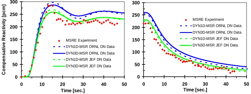
In the frame of the MOST project, a validation benchmark was defined, based on the experimental data measured during the MSRE [10]. The cross-section libraries appropriate for the calculation were prepared by EdF using the Apollo code [11]. The benchmark was calculated by means of different codes in five institutions [12]. For the validation of DYN3D-MSR neutronics, especially the fuel pump start-up and coast-down transients are important. During these two transients the fuel flow velocity varies and the DN distribution is changing. However, constant power is maintained by means of control rods (Fig. 7).
0 50 100 150 200 250 300
0 10 20 30 40 50
Time [sec.]
C
o
m
p
e
n
s
at
ive
R
e
act
iv
it
y [
p
cm
]
MSRE Experiment
DYN1D-MSR ORNL DN Data
DYN3D-MSR ORNL DN Data
DYN1D-MSR JEF DN Data
DYN3D-MSR JEF DN Data
0 50 100 150 200 250 300
0 10 20 30 40 5
Time [sec.]
0 MSRE Experiment
DYN1D-MSR ORNL DN Data
DYN3D-MSR ORNL DN Data
DYN1D-MSR JEF DN Data
DYN3D-MSR JEF DN Data
Fig. 7: Compensative reactivity inserted by control rods during the fuel pump start-up (left)
and coast-down (right) transients for original ORNL and calculated JEF DN data.
After successful validation, the code was applied to several hypothetical transients in a typical MSRE core. The 300 pcm prompt reactivity jump is presented here as an example of different power transients. The power increases rapidly during the first few seconds of this transient. However, the response of fuel salt temperature is immediate and the power increase is slowed-down rapidly due to the negative reactivity introduced by the fuel temperature. The long-term behavior is determined by the slowly growing graphite temperature through the moderator temperature feedback coefficient (Fig. 8).
0 1 2 3 4 5 6 7 8 9 10
0 5 10 15 20 25 30
Time [sec.]
R
e
la
ti
v
e
p
o
we
r
650 654 658 662 666 670 674 678 682 686 690
Te
m
pe
ra
tur
e
[
°C
]
Relative power
Average Fuel Temperature Average Graphite Temperature
7. SUMMARY AND OUTLOOK
The delayed neutrons drift and the direct release of fission energy into the liquid fuel are two attributes specific to MSR dynamics. The appropriate models have been integrated into the DYN3D-MSR code. The code was validated against the experimental results from the MSRE. Then it was applied to several hypothetical transients analyses, where space-dependent effects are relevant. In the considered transients, the response of the MSR is characterized by the immediate change of the fuel temperature with changing power and fast negative temperature feedback to the power.
The DYN3D-MSR code has been shown to be an effective tool for MSR dynamics studies. In the future the code is scheduled to be extended by modeling the heat exchanger between primary and secondary circuit and by considering the reprocessing unit, to cover a wider spectrum of transients.
ACKNOWLEDGE
The work reported about was partially funded by the EC within the project MOST (contract FIKI-CT-2001-20183).
REFERENCES
[1] H. G. MacPherson: “The Molten Salt Reactor Adventure”, Nuclear Science and engineering: 90, 374-380, 1985.
[2] “A Technology Roadmap for Generation IV Nuclear Energy Systems”, Issued by the U.S DOE Nuclear Energy Research Advisory Committee and the Generation IV International Forum, December 2002. [3] J. Křepel, U. Grundmann, U. Rohde: “Development and Verification of Dynamics Code for Molten salt
Reactors”, Proceedings of ICONE 12 conference, Arlington, Virginia (Washington, D.C.), USA, 25-29 April, 2004.
[4] U. Grundmann, U. Rohde, S. Mittag: “DYN3D - Three-Dimensional Core Model for Steady-State and Transient Analysis of Thermal Reactors”, Proc. of Int. Topl. Mtg. on Advances in Reactor Physics and Mathematics and Computation into the Next Millennium (PHYSOR2000), Pittsburgh (USA), 7-11 May, 2000.
[5] J. Křepel, U. Grundmann, U. Rohde: “Development and Verification of a Dynamics Code for Molten salt Reactors with Flowing Fuel”, Annual Meeting on Nuclear Technology 2003, Berlin, Germany, 20-22 May, 2003.
[6] U. Grundmann: “HEXNEM – A Nodal Method for the Solution of the Neutron Diffusion Equation in Hexagonal Geometry“, Proceedings of the M&C’99 Conference on Mathematics and Computations in Nuclear Applications, pp. 1086-1095, Madrid, September, 27 – 30, 1999.
[7] U. Rohde: “Ein theoretisches Model für Zweiphasenströmung in wassergekühlten Kernreaktoren und seine Anwendung zur Analyse des Naturumlaufs im Heizreaktor AST-500”, Dissertation, Zentralinstitut für Kernforschung Rossendorf bei Dresden, Juli 1986.
[8] P.R. Kasten, et al.: “Graphite behavior and its effects on MSBRE performance.“ ORNL, USA, 1968. [9] P. N. Haubenreich: “Molten-Salt Reactor Experiments”, ORNL-4396, 1970.
[10] B. E. Prince, J. R. Engel, S. J. Ball, P. N. Haubenreich, T. W. Kerlin: “Zero-Power Physical Experiments on Molten-Salt Reactor Experiment“, ORNL-4233, 1968.
[11] R. Sanchez et Al.: ''APOLLO II: a User-Oriented, Portable, Modular Code for Multigroup Transport Assembly Calculations'', Congress on Advances in Reactor Physics, Mathematics and Computation, Paris, Vol. 1, 1563-1577, 1987.