Quality Enhancement of Low Resolution
Biomedical Images Using Multi-Wavelet
Transform and Interpolation Method
Neha S. Deshmukh, Dr. Sanket B. Kasturiwala
M. E Student, Dept. of EXTC, Sipna C.O.E.T., SGBAU University, Amravati, India
Assistant Professor, Dept. of EXTC, Sipna C.O.E.T., SGBAU University, Amravati, India
ABSTRACT: Many digital imaging applications requires high resolution images or videos for later image processing and analysis. The need for high quality image is one of the major challenges in image processing. Image processing plays a vital role in wide variety of application in the recent years. One of the important and emerging field in the area of medical imaging applications. One of the most important quality factors in images comes from its resolution. Quality of the image in terms of its resolution is the major parameters for accurate diagnosis of the diseases. Medical images typically suffer from many imperfections thus visual appearance of an image and image quality can be improved by the various enhancement techniques. In this project, Multi-Wavelet transform and Interpolation method is used for resolution enhancement. An image is decomposed in to different subbands using Discrete Wavelet Transform and Stationary Wavelet Transform like LL, LH, HL and HH. DWT includes down sampling and SWT does not include any down sampling. Bilinear Interpolation is used to interpolate DWT coefficients. Inverse Stationary Wavelet Transform is used to reconstruct an image. Finally, Performance can be measured by using statistical parameters such as peak signal to noise ratio (PSNR), mean square error (MSE), root mean square error (RMSE) and correlation factor.
KEYWORDS: Discrete Wavelet Transform, Stationary Wavelet Transform, Inverse Stationary Wavelet Transforms, High Resolution, Low Resolution, Interpolation.
I. INTRODUCTION
The recent increase in the wide use of digital imaging technologies in consumer application, security application and military application has demand for higher-resolution images. The demand for such high- resolution (HR) images can be met by algorithmic advances in resolution enhancement techniques. The resolution enhancement technique enhance the image resolution and make it clearer for human as well as machine in view for better information extraction which are not visibly clear in low resolution images. The output high resolution image not only gives the pleasing picture but also offer additional details that are important for analysis in many applications. Image processing plays a vital role in wide variety of application in the recent years. One of the important and emerging field in the area of medical imaging applications. Medical images typically suffer from one or more of the following imperfections such as Low resolution, High level of noise, Low contrast, Geometric deformations, Presence of imaging artefacts. These imperfections can be inherent to the imaging modality (e.g. X-rays offer low contrast for soft tissues, ultrasound produces very noisy images). The biomedical application requires high resolution images for later image processing and analysis. The need for high quality image is one of the major challenges in image processing. So main aim of our project is to obtain High-resolution (HR) images from Low resolution (LR) images.
II. RELATED WORK
they are not appropriate for face recognition, it is important to improve the resolution of images extracted from surveillance cameras. This research focuses on resolution refinement of very low resolution (VLR) images. The main objective of this study is to refine the resolution of face images and to estimate high resolution image of human face in different poses which not even a low resolution image of that pose exists. For this purpose a method based on reconstruction or estimation of the desired image by using other human face images, stored in a database, is proposed.
Abdullah Al-Shabili, Bilal Taha and Hussain Al-Ahmad [2] proposed Super-resolution Algorithm for Satellite Still Images. This paper presents a new algorithm for improving the resolution of satellite images. The improvement aims at obtaining a high resolution image from a single low resolution image. The new algorithm utilizes interpolation and two dimensional filter specifically designed for a particular image by means of maximizing the peak signal to noise ratio (PSNR). The performance of the algorithm is evaluated by using the PSNR. During the assessment process the processed images are compared with a ground truth images.
Yusuke Hayashi, Norihiko Kawai, Tomokazu Sato and Naokazu Yokoya[3] had implemented Image Resolution Enhancement Based On Novel View Synthesis. In the proposed method, they generate example images by a novel view synthesis technique using 3D geometry reconstruction and camera pose estimation from a video or images capturing the same scene. They then increase their solution by minimizing an energy function by searching for the optimal example from the generated example images.
Hasan Demirel and Gholamreza Anbarjafari [5] had implemented Satellite Image Resolution Enhancement Using Complex Wavelet Transform. In this paper, a satellite image resolution enhancement technique based on interpolation of the high-frequency subband images obtained by dual-tree complex wavelet transform (CWT) is proposed. DT-CWT is used to decompose an input low-resolution satellite image into different subbands. Then, the high-frequency subband images and the input image are interpolated, followed by combining all these images to generate a new high-resolution image by using inverse DT-CWT. The high-resolution enhancement is achieved by using directional selectivity provided by the CWT, where the high-frequency subbands in six different directions contribute to the sharpness of the high-frequency details such as edges.
III. PROPOSED ALGORITHM
A. Proposed System Implementation
The proposed technique is designed to obtain HR images which can offer more details for accurate diagnosis in biomedical applications.
Implementation of image enhancement method as shown in above figure. Low resolution image is applied to DWT and SWT. DWT decompose the image into four subbands namely, LL, LH, HL and HH respectively. The LL image is considered a reduced version of the original and it represents averaging system. The LH, HL and HH represent detail system. The DWT includes downsampling of components by 2. The SWT decomposed signal in to four subband and upsampling the filter coefficients by a factor of 2 in the level of the algorithm. Here the filter coefficient upsampled by 1. The detail components of DWT interpolate by factor 2 and added with detail components of SWT. Then fused components are applied to ISWT. ISWT reconstruct the image with the help of fused components and approximate component of SWT. Then reconstructed image is interpolated by factor 2 to obtain High resolution image. B. Discrete Wavelet Transform
In numerical analysis and functional analysis, a discrete wavelet transform (DWT) is any wavelet transform for which the wavelets are discretely sampled. As with other wavelet transforms, a key advantage it has over Fourier transforms is temporal resolution: it captures both frequency and location information (location in time). The discrete wavelet transform has a huge number of applications in science, engineering, mathematics and computer science. Most notably, it is used for signal coding, to represent a discrete signal in a more redundant form, often as a preconditioning for data compression.
DWT can be implemented through sub-band coding. Sub-band coding is a procedure in which input signal is subdivided into several frequency bands. Sub-band coding implemented through filter bank. A filter bank is collection of filters having either common input or common output. When the filters have a common input they form an analysis bank and when they share common output, they form a synthesis bank. In DWT, an image can be analyzed by passing it through an analysis filter bank followed by decimation operation.
The DWT of a signal“x” is calculated by passing it through a series of filters. First the samples are passed through a low pass filter with impulse response “g” resulting in convolution of the two:
( ) = ( ∗ )[ ] = [ ] ∞
∞
[ − ]
The signal is also decomposed simultaneously using a high pass filter. The outputs giving the detail coefficients ( from the high pass filter) and approximation coefficients (from the low pass). It is important that the two filters are related to each other and they are known as a quadrature mirror filter. The filter outputs are then subsample by 2.
( ) = [ ] ∞
∞
[2 − ]
( ) = [ ] ℎ ∞
∞
[2 − ]
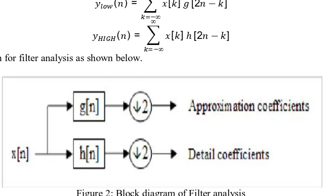
Basic block diagram for filter analysis as shown below.
Figure 2: Block diagram of Filter analysis
filter which corresponds to differencing operation, extract detail information of signal. The output of filtering operation is then decimated by two. A two dimensional transform is accomplished by performing two separate one dimensional transforms. First the image is along the row and decimated by two. It is then followed by filtering the sub-image along the column and decimated by two. This operation splits the image in to four bands, namely, LL, LH, HL and HH respectively. The LL image is considered a reduced version of the original as it retains most details. The LH image contains horizontal edge features, while the HL contains vertical edge features. The HH contains high frequency information only and is typically noisy and is, therefore, not useful for the registration. In wavelet decomposition, only the LL image is used to produce the next level of decomposition.
Figure 3: Discrete Wavelet Decomposition
C. Stationary Wavelet Transform
Stationary wavelet transform (SWT) is a wavelet transform algorithm designed to overcome the lack of translation-invariance of the discrete wavelet transform (DWT). Translation invariance is achieved by removing the downsamplers and upsamplers in the DWT and upsampling the filter coefficients by a factor of 2 in the level of the algorithm. This algorithm is more famously known as "algorithme à trous" in French (word trous means holes in English) which refers to inserting zeros in the filters. Stationary Wavelet Transform (SWT) is similar to Discrete Wavelet Transform (DWT) but the only process of downsampling is suppressed that means the SWT is translation-invariant. The 2-D SWT decomposition scheme is illustrated in following figure 4.
Figure 4: Stationary Wavelet Decomposition
As with the decimated algorithm, the filters are applied first to the rows and then to the columns. The 2D Stationary Wavelet Transform (SWT) is based on the idea of no decimation. It applies the Discrete Wavelet Transform (DWT) and omits both down-sampling in the forward and up-sampling in the inverse transform. More precisely, it applies the transform at each point of the image and saves the detail coefficients and uses the low frequency information at each level.
D. Inverse Stationary Wavelet Transform
transform is restoring the signal from decomposed signal. As a signal is decomposed in multilevel sub-bands then that signal is recomposed from the decomposed signal. For accurate analysis signal should be reconstructed. The performance of a reconstructed image is check by using some parameter like Peak Signal to Noise Ratio (PSNR), Mean Square Error (MSE) etc.
E. Bilinear Interpolation
Bilinear interpolation is an extension of linear interpolation for interpolating functions of two variables
(e.g.,x and y).The key idea is to perform linear interpolation first in one direction, and then again in the other direction. Bilinear interpolation considers the closest 2x2 neighborhood of known pixel values surrounding the unknown pixel. It then takes a weighted average of these 4 pixels to arrive at its final interpolated value. The algorithm for bilinear interpolation as shown in figure 5 .Figure 5: Bilinear Interpolation Algorithm
The four red dots show the data points and the green dot is the point at which we want to interpolate.Suppose that we want to find the value of the unknown function f at the point (x, y).It is assumed that we know the value of f at the four points Q11 = (x1, y1), Q12 = (x1, y2), Q21 = (x2, y1), and Q22 = (x2, y2).
Linear interpolation in the xdirection is given by,
( , ) = x −x
x −x ( ) +
x−x
x −x ( )
( , ) = x −x
x −x ( ) +
x−x
x −x ( )
Linear interpolation in the ydirection is given by,
( , ) = −
− ( , ) +
−
− ( , )
IV. SIMULATION RESULTS
A. Steps to Perform
Step 1: Load low resolution biomedical image. Step 2: Check whether image is color or grayscale Step 3: If image is color,
Step 4: Apply DWT & SWT
Step 5: Interpolate the DWT components by 2.
Step 7. Apply Inverse-SWT to RGB
Step 8: Interpolation of reconstructed image by 2. Step 9: Obtain high resolution image.
Step 10: If image is grayscale repeat steps from 4 to 9.
B. Experimental Results
Figure: LR image
Figure: One step SWT decomposition
Figure: One step DWT decomposition
Figure: ISWT
Table 1 describes analysis of performance parameters such as PSNR, MSE, RMSE etc for various test images.
Sr. No. Test Images MSE RMSE PSNR
(In db)
Correlation
Coefficient
SNR
1 Test Image 1 2.0085 1.1905 45.1021 0.9995 21.9383
2 Test Image 2 1.8901 1.1725 45.3660 0.9994 21.4001
3 Test Image 3 2.2805 1.2289 44.5504 0.9994 20.6825
4 Test Image 4 1.4429 1.0960 46.5383 0.9981 15.1081
5 Test Image 5 1.8921 1.1728 45.3615 0.9992 19.8243
6 Test Image 6 1.4966 1.1061 46.3796 0.9991 19.1919
7 Average Value 1.8351 1.1611 45.5496 0.9991 19.6908
Table 1: Analysis of different performance parameter
V. CONCLUSION AND FUTURE WORK
This paper discusses about improvement in the resolution of biomedical images based on the multi-wavelet transform using interpolation techniques. Multi-Wavelet transform and Interpolation method is used for resolution enhancement. An image is decomposed in to different subbands using Discrete Wavelet Transform and Stationary Wavelet Transform like LL, LH, HL and HH. DWT includes down sampling and SWT does not include any down sampling. Bilinear Interpolation is used to interpolate DWT coefficients. Inverse Stationary Wavelet Transform is used to reconstruct an image. Finally, Performance can be measured by using statistical parameters such as peak signal to noise ratio (PSNR), mean square error (MSE), root mean square error (RMSE) and correlation factor. The quantitative metrics (PSNR, MSE) of the image calculated shows the superiority of DWT-SWT technique. For achieving visually acceptable HR images, image enhancement algorithm provides wide range of approaches. Based on the image type and noise type with which it is corrupted, a slight change in individual method or combination of any methods further improves visual quality. The future scope will be the development of adaptive algorithms for effective image enhancement using Fuzzy Logic and Neural Network and curvelet enhancement techniques.
REFERENCES
1] Yashar Kiarashi Nejad, Mohammadali Masnadi-Shirazit, Mehran Yazdi, Mohamadreza Zand Shahvar,“ Quality Enhancement of Low-Resolution Face Images”, 9th Iranian Conference on Machine Vision and Image Processing,N ovember 18-19,2015; Shahid Beheshti University - Tehran, Iran ,2015 IEEE.
2] Abdullah Al-Shabili, Bilal Taha and Hussain Al-Ahmad, “ Super-resolution Algorithm for Satellite Still Images”,2015International Conference on Information & Communication Technology Research (ICTRC2015),2015 IEEE.
3] Yusuke Hayashi, Norihiko Kawai, Tomokazu Sato and Naokazu Yokoya, “Image Resolution Enhancement Based On Novel View Synthesis”, 2015 IEEE.
4] Darshana Mistry, Asim Banerjee, “Discrete Wavelet Transform using Matlab,” International Journal of Computer Engineering and Technology (IJCET) Volume 4, Issue 2, March – April (2013), pp. 252-259
6] Sreejith.S and Tripty Singh, “A New Technique For Image Enhancement In Biomedical Applications”, ISSN (Online): 2347-2820, Volume -2, Issue-1, January, 2014.
7] Hsin-Yi Tsai, Kuo-Cheng Huang, Min-Wei Hung, Chih-Chung Yang, Ching-Ching Yang, “The Field of View and Resolution of Marco Images Enhanced by Modified Superresolution Method”, 2015 IEEE Instrumentation and Measurement.
8] Giri Nandan and Navdeep Kanwal, “Image Resolution Enhancement Methods for Different Applications”, International Journal of Information & Computation Technology, ISSN 0974-2239 Volume 4, Number 17 (2014), pp. 1733-1738.
9] Rithu James and Supriya M H Department of Electronics Cochin University of Science & Technology Kochi, “Spatial Resolution Enhancement of Sonar Images Using One Step Pixel Prediction”, 2015 International Conference on Control, Communication & Computing India (ICCC) | 19-21 November 2015 | Trivandrum.