ISSN(Online): 2320-9801
ISSN (Print): 2320-9798
I
nternational
J
ournal of
I
nnovative
R
esearch in
C
omputer
and
C
ommunication
E
ngineering
(An ISO 3297: 2007 Certified Organization)
Vol. 4, Issue 8, August 2016
Multi-Band CPW-Fed Flexible and
Transparent Antenna for Active ISM RFID
Tag using Genetic Algorithm
K. Deepak 1, K. Rama Devi 2
M.Tech, Department of ECE, JNTUK, Kakinada, India1
Asst. Professor, Department of ECE, JNTUK, Kakinada, India2
ABSTRACT: In this paper multi-band coplanar waveguide-fed antenna for ISM active RFID application is designed and optimized using adaptive genetic algorithm (AGA). The optimization goals are gain maximization and bandwidth enhancement. Here silver coated conductive polymer AgHT-8(AgF8) thin film used as CPW ground and radiator. Polyethylene terepthalate (PET) is used as substrate, to design the antenna with transparency of above 80%. The antenna is designed at multiple frequencies1.5 GHz, 2.4 GHz, 3.5 GHz and 5.8 GHz. The overall dimension of proposed antenna is 39X36X0.175 mm. The antenna is suitable for WiMax, GPS, Wi-Fi, Bluetooth and ISM applications. The proposed antenna is considerably light weight and less thickness compared with non transparent designs. Antenna model is simulated in Ansoft HFSS and Matlab.
KEYWORDS: Keywords – Multi band, Transparent, Genetic Algorithm, RFID, Active Tag, PET, AgHT-8, CPW, ISM, Flexible.
I. INTRODUCTION
Today, automation technology plays a major role in industries, transportation and domestic sectors [1-5]. In automation process identification and tracking of objects is major task. Some of familiar techniques to identify and tracking objects are Bar code, QR code, and Radio Frequency Identification (RFID). The advances in several applications involving identification, detection, vehicular communication [6] and navigation [7,8] require antennas which are conformal and optically transparent. These special antennas are not only required for detection and navigational communication but are also necessary to enhance performance such as security, light weight and aesthetic. Transparent antennas are designed with transparent materials or meshed conductors.
Sapphire, RT duroid, and polyethylene etc having transparent nature and used as substrate in transparent antennas. Previously, Patch and ground are designed with non transparent conducting materials, due to this visibility of antenna increases and it is not consider as transparent antenna. In recent years transparent conducting materials are developed like conductive silver ink. The meshed antennas are fabricated from printing with conductive ink or from electroformed mesh. High surface resistance due to meshed lines is one of the limitations [9].
RFID applications are designed at High Frequency (HF), Ultra High Frequency (UHF) and microwave Industrial Scientific and Medical (ISM) band range. HF and UHF band RFID tags transfer low data due to low frequency. Microwave band RFID antennas transfer high data rates because of high frequency and at the same time size of antenna is less compared to HF and UHF antennas. High speed data transfer is required between tag and reader for tracking of moving object [6]. RFID tag contains a tag antenna and an IC chip. RFID antennas are classified into 3 types according to powering-up Integrated Circuit (IC) chip as passive tag antenna, semi passive tag antenna and active tag antenna [10]. In passive RFID tag antennas, RFID reader transmits signal first and receives back scatter signal from tag. No need of any additional power source in passive tag antenna. If impedance matching between tag and IC is more, then tag receives more power [11]. In case of active RFID system no need of reader to transmit signal to power up IC because an onboard power supply is available on active RFID tag. Hence design of active antenna is simple compared to passive tag antenna. So active RFID antenna at microwave attracting researcher’s interest.
ISSN(Online): 2320-9801
ISSN (Print): 2320-9798
I
nternational
J
ournal of
I
nnovative
R
esearch in
C
omputer
and
C
ommunication
E
ngineering
(An ISO 3297: 2007 Certified Organization)
Vol. 4, Issue 8, August 2016
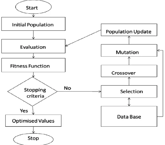
generate and selects best population to next generations, this population is called parents. By using best parents, offspring are produced using crossover technique. In crossover technique, part of parent value is interchange between two parents to produce best off spring. After crossover one or more values of new population is changed, this is called mutation. Now this new population is applied to problem and observe solution using fitness function. This fitness function contains the goal of the problem solution. If solution reached desired goal, optimization stops otherwise the process continues until it reach stopping criteria.
In order to connect antenna with RFID system different fed mechanisms are using in active RFID system like Co-Planar Wave guide (CPW) fed and probe fed mechanism. In probe fed technique, slight variation in probe position leads to significant change in antenna performance and also at lower thinness of antennas; probe fed fabrication is difficult [13]. To overcome these drawbacks, CPW fed technique is utilizing, owing to ease of implementation and fabrication [14]. Multiband CPW fed transparent antenna at ISM band with operating frequencies of 2.4GHz, 3.5GHz and 5.8GHz for different applications are RFID, WiMax, Wi-Fi, Bluetooth and GPS. ISM band of 2.4GHz, 3.3GHz, 5.65GHz [15], GPS bands of L band (1.5GHz) and S band 2.4GHz[16] and WiMax bands of 2.5GHz and 3.5GHz [17]. The proposed antenna covers resonating bandwidth of 2.2 GHz from 1.5 GHz to 3.7 GHz and bandwidth of 0.7 GHz from 5.3 GHz to 6.0 GHz
The rest of the paper is organized as follows. Related Work is explained in section II. Proposed antenna deign is explained in section III. Simulation results are presented in section IV. Concluding remarks are given in section V.
II. RELATED WORK
In [2], optically transparent antenna is investigated. The conventional microstrip line fed patch antenna designed using RT-Duroid 5880 substrate is not optically transparent. Conformal and optically transparent antennas are need for applications involving vehicular communications and navigation. These special antennas not only required for communication and navigation but also necessary to enhance the vehicular performance, such as, aesthetic and security. In [4], label type UHF antenna is investigated. To achieve flexibility to antenna in this paper PET substrate is used and antenna designed to operate at UHF band. In [5], need of GPS and RFID system is investigated for localization and tracking. In [6], RFID road marker navigation system is investigated. In this paper RFID system is using as alternate, where GPS not works. In [9], property of optically transparent patch antenna for meshed conductor and transparent films is investigated. In [18], the optimization of a meander line antenna FEM model by means of an adaptive genetic algorithm is investigated. To search for optimal antenna configurations, the present method employs a GA with an adaptive method that adjusts the characteristics of its selection, crossover and mutation operators in order to maintain a diverse set of high quality candidate solution during its execution. In [4], a single UHF band probe-fed transparent antenna for RFID applications is investigated using the printed conductive polymer on the polyethylene terepthalate (PET) substrate. In the design, a modified polymer is used to increase the conductivity of the material; however, it increased the visibility to the human eye. In addition, a slight deviation from the exact position of the feed line will significantly decrease the performance of the antenna. To avoid this drawback, the CPW-fed technique could be utilized, owing to ease of fabrication and implementation [13]. In [24], a dual band CPW-Fed active antenna for ISM active RFID is investigated using AgHT-8 thin film. In the design, antenna is designed to operate only at 2.45 GHz and 5.8 GHz; however this antenna is not useful for GPS function for localisation and tracking [5] along RFID system. In addition the gain of antenna is acceptable, but less.
III.ANTENNA DESIGN
ISSN(Online): 2320-9801
ISSN (Print): 2320-9798
I
nternational
J
ournal of
I
nnovative
R
esearch in
C
omputer
and
C
ommunication
E
ngineering
(An ISO 3297: 2007 Certified Organization)
Vol. 4, Issue 8, August 2016
Mutation process in genetic algorithm. This process continues until optimization meets desired goal or stopping criteria.
Figure 1. Antenna Design Model
Proposed antenna shown in Figure 1 is designed using AgHT-8 thin film. AgHT-8 is above 80% transparent to human eye [23]. AgHT-8 is composition of two layers, poly teraphatalet as substrate and silver conductive polyester as radiating layer [23]. Antenna is designed as coplanar waveguide because of low thickness. Radiating patch is polygon shape (similar to semi octagonal shape).
ISSN(Online): 2320-9801
ISSN (Print): 2320-9798
I
nternational
J
ournal of
I
nnovative
R
esearch in
C
omputer
and
C
ommunication
E
ngineering
(An ISO 3297: 2007 Certified Organization)
Vol. 4, Issue 8, August 2016
Here monopole antenna resonates at 1.7 GHz, 2.4 GHz, 3.5 GHz and 5.8 GHz and size of antenna is 39mmx37mmx0.175mm at this dimension 5.8 GHz frequency resonates. In order to achieve low frequencies at this dimension some of the techniques are used. Triangular cuts are used to limit dimensions of antenna at low frequencies 1.5 GHz and 2.4 GHz and also these cuts reduces the mutual coupling between radiating patch and ground plate. If mutual coupling between ground and radiating patch is more, current flow to upper levels of ground plates decreases and this decreases gain [24]. To increase flow of current to upper level of ground plates triangular cuts are made to radiating patch, which reduces mutual coupling. The wide slot ground with long stubs mounted on top of antenna helps to return distributed currents and covers the waste area around radiating patch to avoid large antenna size mainly at lower frequencies. Width of patch is directly proportional to upper resonant frequency i.e., 5.8 GHz [24] and it is not shown any effect on resonance at lower frequencies, at the same time height of patch is inversely proportional to magnitude of return loss at lower frequencies [24]. For 3.5 GHz parasitic polygon is used. Due to this parasitic radiator bandwidth at lower frequencies is increased and gain is improved from - 1.5dBi to 0.5dBi, besides that overall gain also improved. Here 50O CPW fed is using for matching purpose. Two rectangular slots and hexagonal slots are used to resonate, antenna at 5.8 GHz [26].
Table 1: Antenna Parameters
Parameter D
D1
L
L1
L3
PL
RL
RL1
RW
S
Size(mm) 0.35
1.5
39
37
17.2
12
20
23
10
3
Parameter S1
SL
SW
T1
T2
T3
W
W1
W2
W3
Size(mm) 3.6
0.5
4
8.48
5.65
3
36
19.2
12.5
4
To search optimized antenna parameters, Adaptive genetic algorithm is using and flow chart is shown in Figure 2. Genetic algorithm is a process in which candidate solution is optimized iteratively varying the values of each candidate. Here a candidate is nothing but a length or width or position of antenna elements. These candidate values are changes iteratively by 3 steps, called selection, crossover and mutation [12]. In this algorithm all candidates are not participate in these 3 steps, only candidates which are need to optimize are participate in 3 steps, this can be done by comparing previous data available in data base and current results. In selection process, candidates are selected using tournament model. Candidate which are best in candidate solution set are taken. In mutation, a value is either increase or decrease. AGA takes a decision by using previous and current data to increase or decrease value.
IV.RESULTS
ISSN(Online): 2320-9801
ISSN (Print): 2320-9798
I
nternational
J
ournal of
I
nnovative
R
esearch in
C
omputer
and
C
ommunication
E
ngineering
(An ISO 3297: 2007 Certified Organization)
Vol. 4, Issue 8, August 2016
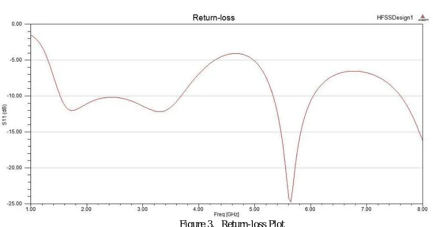
Return loss of proposed antenna is shown in Figure 3. It is clear that proposed antenna resonates at 1.7GHz, 3.1GHz and 5.7GHz and magnitude of return-loss is -11.96 dB, -12 dB and -24.7 dB respectively. It also covers ISM band, WIMAX, GPS band as shown in Figure 3. Antenna purposed in paper [24], covers only 2.4GHz and 5.8GHz ISM bands only.
Figure 4. VSWR Plot
Proposed antenna has VSWR < 2 over frequency ranges from 1.5GHz to 3.7GHz and from 5.3GHz to 6.1GHz shown in Figure 4. Gain of proposed antenna in paper [24] is a -2.5dBi, -4.5dBi at 2.4GHz and 5.8 GHz respectively.
ISSN(Online): 2320-9801
ISSN (Print): 2320-9798
I
nternational
J
ournal of
I
nnovative
R
esearch in
C
omputer
and
C
ommunication
E
ngineering
(An ISO 3297: 2007 Certified Organization)
Vol. 4, Issue 8, August 2016
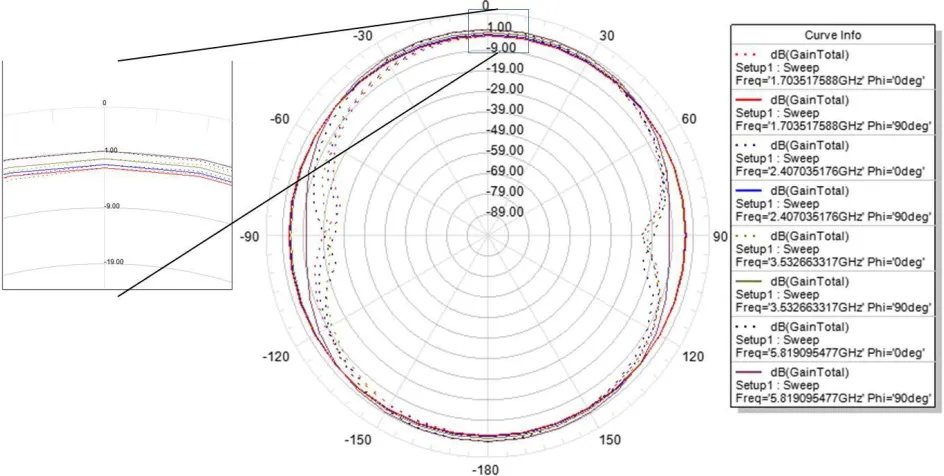
This patch improved overall gain around 3dBi.the radiation patter of proposed antenna is almost Omni directional. At frequency 1.7 GHz, return loss is -11.96dB, gain is -1.8 dBi and radiation pattern is similar to Omni directional, a null point can observe in bore side. At frequency 2.4 GHz, return loss is -10.2dB, gain is -1.2 dBi and radiation pattern is similar to Omni directional, a null point can observe in bore side. At frequency 3.5 GHz return loss is -11.6 dB, gain is -0.24 dBi and radiation pattern is similar to Omni directional, a null point can observe in bore side. At frequency 5.8 GHz return loss is -15.9 GHz, gain is 1.15dBi and radiation pattern is similar to Omni directional, a null point can observe in bore side. Average 99.3% radiation efficiency is achieved.
Figure 6. 3-D Radiation Pattern of Proposed Antenna
V. CONCLUSION AND FUTURE WORK
An antenna is designed to operate at different frequency bands like 1.7GHz, 2.4GHz, 3.5GHz and 5.8GHz using adaptive genetic Algorithm optimization method and antenna radiation pattern is observed using Ansoft HFSS simulation software. Proposed antenna covers bandwidth of 2.2GHz from 1.5GHz to 3.7GHz and 0.7GHz from 5.3GHz to 6GHz with return loss < -10dB and VSWR<2. This antenna can use for different applications like RFID, WiMax, Bluetooth, GPS and Wi-Fi.
REFERENCES
1. Bing Li, Jingsong Hong, and Bingzhong Wang, “Switched Band-Notched UWB/Dual-Band WLAN Slot Antenna With Inverted S-Shaped Slot”, IEEE Antennas And Wireless Propagation Letters, Vol.12, pp. 572-575, 2012.
2. Rainee N. Simons, Ricard Q. Lee, “Feasibility Study of Optically Transparent Microstrip Patch Antenna”, International Symposium and Radio Science Meeting, NASA TM-107434, 1997.
3. Toni Bjorninen,lauri Sydanheimo,Leena Ukkonen and Rahmat-Sami, “Advances in Antenna Design for UHF RFID Tags Mounted on Conductive Items”, IEEE Antennas and Propagation Magazine, Vol.56, No. 1,pp.79-103, 2014.
4. Tae-Wan Koo, Dongsu Kim, Jong-In Ryu, Hae-Moon Seo, Jong-Gwan Yook, and Jun-Chul Kim, “Design of a Label-Typed UHF RFID Tag
Antenna for Metallic Objects”, IEEE ANTENNAS AND WIRELESS PROPAGATION LETTERS, Vol.10, pp. 1010-1014, 2011.
5. Nader Moayeri, Jalal Mapar, Stefani Tompkins and Kaveh Pahlavan, “Emerging Opportunities for Localization and Tracking”, IEEE Wireless Communication, pp. 8-9, 2011.
6. Jinxi Chen, Yen Bao Le, and Sungkyun Lim, “A Passive UHF RFID Tag Antenna for Road Marker Navigation Application”, IEEE AP-S, pp.
1752-1753, 2015.
7. S. Radacina Rusum M. J. D. Hayes, J. A. Marshall, “Localization in large-scale Underground Environments with RFID”.
8. Nicolo Decarli, Francesco Guidi, Davide Dardari, “A Novel Joint RFID and RADAR sensor Network for Passive Localization: design and Performance Bounds”, IEEE JOURNAL OF SELECTED TOPICS IN SIGNAL PROCESSING, Vol.8, NO. 1, pp. 80-95, 2014.
9. Tursunjan Yasin,Reyhan Baktur and Cynthia Furse, “A comparative Study on Two Types of Transparent Patch Antennas”, in IEEE 2011.
10. K. Finkenzeller, RFID Handbook: Fundamentals and Applications in Contactless Smart Cards and Identification. New York: Wiley, 2003. 11. C onstantine A. Balanis, Antenna Theory: Analysis and Design. India: Wiley, 2012.
12. J. M. Zurada, Introduction to Artificial Neural Systems: Jaico Publishers, 3rd edition.
13. T. Peter and R. Nilavalan, “A Novel Technique and Soldering Method to Improve Performance of Transparent Polymer Antennas”, IEEE Antennas And Wireless Propagation Letters, Vol.9, pp. 918-921, 2010.
14. Shayan Hakimi, Sharul Kamal Abdul Rahim, Mohammad Abedian, S. M. Noghabaei, M. Khalily, “ CPW-Fed Transparent Antenna for Extended Ultra wide band Applications”, IEEE Antennas And Wireless Propagation Letters, Vol.13, pp. 1251-1254, 2014.
15.
http://www.itu.int/en/ITU-R/study-groups/workshops/RWP1B-SRD-UWB-14/Presentations/International,%20regional%20and%20national%20regulation%20of%20SRDs.pdf
ISSN(Online): 2320-9801
ISSN (Print): 2320-9798
I
nternational
J
ournal of
I
nnovative
R
esearch in
C
omputer
and
C
ommunication
E
ngineering
(An ISO 3297: 2007 Certified Organization)
Vol. 4, Issue 8, August 2016
17. http://www.trai.gov.in/WriteReaddata/ConsultationPaper/Document/3G.pdf
18. P . Guo, X. Wang, and Y. Han, “The enhanced genetic algorithms for the optimization design”, Proc. 3rd Int. Conf. Biomed. Eng. Informat, Vol.7, pp. 2990–2994, 2010.
19. J. M. J. W. Jayasinghe and D.N. Uduwawala, “Design of Broadband patch antennas using genetic algorithm optimization”, IEEE 5th International Conference on Industrial and Information Systems, ICIIS 2010, pp.60-65, 2010.
20. Edward E. Slthuler, “Design of a Vehicular Antenna for GPS/IRIDIUM Using a Genetic Algorithm”, IEEE Transactions on Antenna and Propagation, Vol.48, NO. 6, pp. 968-972, 2000.
21. R. L. Haupt, “An introduction to genetic algorithms for electromagnetic”, IEEE Antennas Propag. Mag., Vol. 37, no. 2, pp. 7–15, Apr. 1995. 22. Yuki Sato, Felipe Campelo and hajime igarashi, “Meander Line Antenna Design Using an Adaptive Genetic Algorithm”, IEEE
TRANSACTIONs ON MAGNETICS, Vol.49, No. 5, pp. 1889-1892, 2013.
23. Instrument Plastic, Ltd., Maidenhead, U.K., “AgHT-8 silver coated polyester thin film,” [Online]. Available:
http://www.instrumentplastics.co.uk
24. M. A. Malek, S. Hakimi, S. K. Abdul Rahim and A. K. Evizal, “Dual-Band CPW-Fed Transparent Antenna for Active RFID Tags”, IEEE ANTENNAS AND WIRELESS PROPAGATION LETTERS, Vol.14, pp.919-922, 2015.
25. Gaetano Marrocco, “The Art of UHF RFID Antenna Design: Impedance-Matching and Size-Reduction Techniques”, IEEE Antenna and Propagation Magazine, Vol.50, No. 1, pp.66-79, 2008.