University of Windsor University of Windsor
Scholarship at UWindsor
Scholarship at UWindsor
Electronic Theses and Dissertations Theses, Dissertations, and Major Papers
2012
Numerical Investigation into Axial Cutting of AA6061-T6 Circular
Numerical Investigation into Axial Cutting of AA6061-T6 Circular
Extrusions Under Blast Loading
Extrusions Under Blast Loading
Keivan Amini University of Windsor
Follow this and additional works at: https://scholar.uwindsor.ca/etd
Recommended Citation Recommended Citation
Amini, Keivan, "Numerical Investigation into Axial Cutting of AA6061-T6 Circular Extrusions Under Blast Loading" (2012). Electronic Theses and Dissertations. 5370.
https://scholar.uwindsor.ca/etd/5370
NUMERICAL INVESTIGATION INTO AXIAL CUTTING OF AA6061-T6 CIRCULAR EXTRUSIONS UNDER BLAST LOADING
by
KEIVAN AMINI
A Thesis
Submitted to the Faculty of Graduate Studies Through Mechanical Engineering in Partial Fulfillment of the Requirements for the Degree of Master of Applied Science at the
University of Windsor
Windsor, Ontario, Canada
2012
NUMERICAL INVESTIGATION INTO AXIAL CUTTING OF AA6061-T6 CIRCULAR EXTRUSIONS UNDER BLAST LOADING
by
KEIVAN AMINI
APPROVED BY:
______________________________________________ Dr. Daniel Green
Department of Mechanical, Automotive and Materials Engineering
______________________________________________ Dr. Nader Zamani
Department of Mechanical, Automotive and Materials Engineering
______________________________________________ Dr. William Altenhof, Advisor
Department of Mechanical, Automotive and Materials Engineering
______________________________________________ Dr. Colin Novak, Chair of Defense
DECLARATION OF ORIGINALITY
I hereby certify that I am the sole author of this thesis and that no part of this thesis has been published or submitted for publication.
I certify that, to the best of my knowledge, my thesis does not infringe upon anyone’s copyright nor violate any proprietary rights and that any ideas, techniques, quotations, or any other material from the work of other people included in my thesis, published or otherwise, are fully acknowledged in accordance with the standard referencing practices. Furthermore, to the extent that I have included copyrighted material that surpasses the bounds of fair dealing within the meaning of the Canada Copyright Act, I certify that I have obtained written permission from the copyright owner(s) to include such material(s) in my thesis and have included copies of such copyright clearances to my appendix.
ABSTRACT
The study detailed in this thesis focuses on the force/time and energy absorption performances of circular AA6061-T6 aluminum alloy extrusions with the wall thickness of 3.175 mm and 1.587 mm subjected to cutting deformation modes under blast loading conditions.
Numerical simulations of the detonation as well as the axial cutting deformation process employing an Eulerian finite element formulation and Smooth Particle Hydrodynamic (SPH) were performed. Numerical detonation models were in good agreement with experimental results having an average standard error less than 3% for impulse predictions. Good predictive capabilities of the numerical model employing the Eulerian element formulation for the axial cutting behaviours were observed, while the SPH formulation failed to predict experimentally observed deformation modes.
The average mean cutting force, measured at the load cell for both experimental and numerical testing methods as a result of cutting deformation was observed to be 18.8 kN and 33.5 kN for the thin- and thick-walled extrusions, respectively.
DEDICATION
To my parents, my brother Kaveh, and my grandmothers
ACKNOWLEDGEMENTS
I would like to thank all of the individuals who have made contributions to this thesis. First and foremost, I would like to express my most sincere gratitude and profound appreciation to Dr. William Altenhof for his supervision, guidance and support. His knowledge, experience, and good sense of humor kept me on track and pushing forward through any difficulties I encountered. I also thank my committee members, Dr. Daniel Green and Dr. Nader Zamani for their advice and comments on this thesis.
TABLE OF CONTENTS
DECLARATION OF ORIGINALITY ... iii
ABSTRACT ... iv
DEDICATION ...v
ACKNOWLEDGEMENTS ... vi
LIST OF TABLES ... xi
LIST OF FIGURES ... xii
LIST OF APPENDICES ... xviii
NOMENCLATURE ... xix
ABBREVIATIONS ... xxi
CHAPTER 1 I. INTRODUCTION...1
1.1 Occupant Protection and Vehicle Safety...1
1.2 Design of blast resistant structure ...3
1.3 Thesis Objectives ...5
1.4 Thesis Organization ...5
II. LITERATURE REVIEW ...7
2.1 Deformation modes for axially loaded tubes ...8
2.1.1Axial plastic collapse ...8
2.1.2Tube inversion ...12
2.1.3Tube splitting ...15
2.2 Factors that influence collapse mode ...20
2.3 Blast phenomena ...23
2.3.1Important factors in Blast ...23
2.3.2Blast loading in numerical simulations ...25
2.4 Finite element modeling of axial crushing of thin-walled extrusions ...27
2.4.1Axial crushing of thin-walled extrusions ...27
2.4.1.1 Lagrangian FE formulation ...27
2.4.1.3 Smooth particle hydrodynamics (SPH) ...36
2.4.2Crush under high intensity blast load ...41
III. CRASHWORTHINESS PARAMETERS ...45
3.1 Total energy absorption...46
3.2 Peak crush load ...46
3.3 Mean crush force ...46
3.4 Crush force efficiency ...47
3.5 Energy efficiency ...47
3.6 Specific energy absorption ...47
3.7 Energy-absorbing effectiveness factor ...48
3.8 Geometric efficiency ...48
IV. FOCUS OF RESEARCH ...49
V. EXPERIMENTAL TESTING METHOD ...51
5.1 Test specimen ...51
5.1.1 Overview of tensile testing of aluminum alloy extrusion 52 5.2 Cutting tool design and manufacturing ...54
5.3 Deflector design and manufacturing ...56
5.4 Piezoelectric load-cell and setup ...56
5.5 Plastic explosive PE4 (C4) ...58
5.6 Ballistic pendulum ...59
VI. FINITE ELEMENT MODELLING AND SIMULATION METHOD ...63
6.1 Explicit finite element analysis ...64
6.2 Eulerian FE formulation ...65
6.2.1Finite element modeling of the detonation ...66
6.2.1.1 Contact modeling of detonation ...67
6.2.1.2 Discretization of detonation model ...68
6.2.1.3 Equation of state for explosives and air ...69
6.2.1.3.1 Equation of state for air ...69
6.2.1.3.2 Equation of state for explosive ...70
6.2.1.4 Material models for detonation model ...72
6.2.2Discretization of the full blast pendulum model ...72
6.3 Smooth particle hydrodynamics (SPH) mesh free formulation 87 6.3.1Discretization of reduced model using the SPH
formulation ...88
6.3.2Discretization of full blast pendulum model using the SPH formulation ...89
6.3.3Contact modeling of the full blast pendulum model ...92
6.3.4Application of boundary conditions ...92
6.3.5Material models ...93
6.3.6Simulation procedure ...94
6.3.7Tensile instabilities in SPH formulation ...94
VII. RESULTS AND DISCUSSIONS ...95
7.1 Experimental results ...95
7.1.1 Blast results of thin AA6061-T6 tubes ...95
7.1.2 Blast results of thick AA6061-T6 tubes ...99
7.1.3Analysis of experimental results ...104
7.1.3.1 Measured results ...104
7.1.3.2 Cut depth and impulse relationship...105
7.1.3.3 Crashworthiness parameter comparison ...106
7.1.3.3.1 Mean crush force ...106
7.1.3.3.2 Peak crush force ...107
7.1.3.3.3 Crush force efficiency ...108
7.2 Numerical results ...110
7.2.1 Detonation results...110
7.2.2 Blast results of thin AA6061-T6 tubes ...113
7.2.3 Blast results of thick AA6061-T6 tubes ...115
7.2.3.1 SPH model results ...116
7.2.3.2 Effect of frictional coefficient on the steady-state cutting process. ...117
7.2.3.3 Strain rate sensitivity of AA6061-T6 ...118
7.2.3Comparison of numerical and experimental results ...120
7.2.4.1 Measured results ...120
7.2.4.2 Finite element model validation assessment ...121
7.2.4.2.1 Validation assessment for the axial blast cutting tests using tube parameters. ...123
7.2.4.2.2 Validation assessment using the formation of dynamic buckling and cutting behaviour .123 7.3 Discussion ...125
7.3.2 Dynamic plastic buckling mode ...125
7.3.3 Influence of wall-thickness ...128
7.3.4 Influence of charge mass ...129
7.3.5 System force/time response...129
7.3.6 SPH model ...129
VIII. OBSERVATIONS OBTAINED IN NUMERICAL AND THEORETICAL ANALYSES ...132
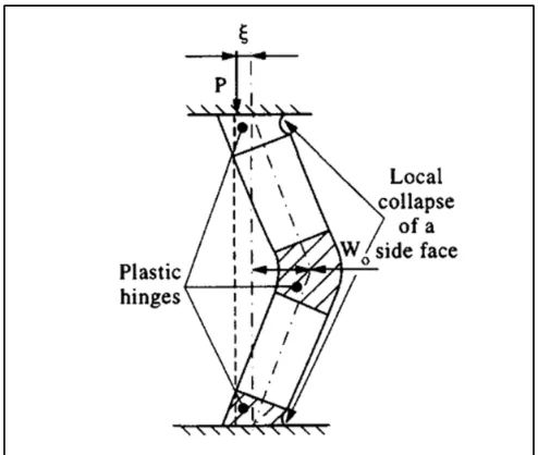
8.1 Characteristics of steady-state cutter cutting process. ...132
8.2 Principle of virtual power ...133
8.3 Assumption for internal energy dissipation ...134
8.4 Force Analyses ...135
8.4.1 Comparison of numerical and theoretical cutting resistance force ...138
8.5 Energy dissipation analyses ...141
8.6 Simplified numerical models ...142
IX. CONCLUSION ...145
9.1 Conclusion for axial cutting test ...145
9.2 Future work ...148
REFERENCES ...149
APPENDIX A: LOAD-CELL SPECIFICATION ...157
APPENDIX B: BALLISTIC PENDULUM THEORY ...157
APPENDIX C: NUMERICAL LOAD VERSUS TIME PROFILES...163
APPENDIX D: NUMERCIAL AND EXPERIMENTAL LOAD VERSUS TIME PROFILES MEASURED AT LOAD-CELL ...168
APPENDIX E: FIGURES COPYRIGHT PERMISSION ...172
LIST OF TABLES
Table 5.1. Material properties of the AA6061-T6 from tensile tests [58]. ...54
Table 5.2. Cutting blades tip width dimensions (mm) [6]. ...55
Table 5.3. Ballistic pendulum physical properties necessary for assessment of impulse ...62
Table 6.1. Material properties for air used in the simulation, from [71]. ...71
Table 6.2. Material properties for PE4 used in the simulation, from [71] ...71
Table 6.3. The material properties of AA6061-T6 ...86
Table 6.4. Various simulations and their aspects considered in this study. ...87
Table 7.1. Experimental results of thin AA6061-T6 specimens ...104
Table 7.2. Experimental results of thick AA6061-T6 specimens ...105
Table 7.3. FE Detonation model validation assessment by equation (7.1) ...111
Table 7.4. Cutting performance measures of the thin-walled specimens from both experimental and numerical testing under blast loading...120
Table 7.5. Cutting performance measures of the thick-walled specimens from both experimental and numerical testing under blast loading...121
Table 7.6. FE model validation assessment by standard value equation. ...122
Table 8.1. Steady-state cutting resistance forces for the axial cutting of circular AA6061-T6 extrusions...139
Table 8.2. Input data for comparison of experimental results with theoretical and numerical predictions [76]. ...140
Table 8.3. Steady-state cutting resistance forces for the thick-walled extrusions in different coefficient of frictions ...141
Table B.1. Geometrical properties from the ballistic pendulum
LIST OF FIGURES
Figure 1.1. Structural damage after frontal offset and side crush test of Smart Fortwo. (a) View after side impact, (b) view of frontal impact [1]. ...2 Figure 1.2. Blast loads on a building [3]. ...4 Figure 2.1. Force versus displacement response for plastic buckling of square tube
collapsing in the global bending mode [7]. ...9 Figure 2.2. Transition to plastic buckling corresponding to point B in Figure 2.1 [7]. ...9 Figure 2.3. Classification chart for collapse modes of aluminum alloy tubes [9]. ...11 Figure 2.4. Progressive buckling mode (a) deformation mode. (b) force/deformation curve [10]. ...12 Figure 2.5. Tube inversion using a die: (a) external inversion, (b) internal inversion [18]. ...13 Figure 2.6. Load/displacement curve for the inversion of Al6060 specimens [21]. ...14 Figure 2.7. Force-compression curves for the mild steel tubes (D=76mm, t=2mm)
compressed on to three different semi-angles α = 45°, 60°, 75° [23]. ...16 Figure 2.8. Photographs of mild steel specimens after tests: from left to right CS7 (α = 45°), CS8 (α = 60°), CS9 (α = 75°) [23]. ...17 Figure 2.9. Crush force efficiency and total energy absorption comparisons among
representative specimens [25]. ...18 Figure 2.10. (a) Geometry of the cutter and (b) Geometry of the deflectors used in
the experimental cutting test (dimensions in mm) [26]. ...19 Figure 2.11. Load/displacement response of AA6061-T6 round tubes under cutting deformation mode in the presence of a cutter and a straight deflector [26]. ...20 Figure 2.12. Load/displacement response of annealed and as-received specimens of (a) aluminum, (b) mild steel [27]. ...21 Figure 2.13. Load–compression curve of aluminum tubes, with and without holes
Figure 2.17. Discretization of extrusion (L = 200 mm, D= 14.2 mm, t= 3.15 mm). The inset shows a detail of the discretization of the circular hole discontinuity region [41]. ...29 Figure 2.18. Experimental and numerical crushing process for 6063-T5 extrusions
[41]. ...30 Figure 2.19. Experimental and numerical crushing process for 6063-T5 extrusions
[41]. ...30 Figure 2.20. (a) Circular tubes with corrugated surface. (b) Tube geometry and
loading condition [42]. ...31 Figure 2.21. Load–displacement curves (a) for various wavelengths 2λ with fixed a and (b) various amplitudes with fixed wavelengths 2λ [42]. ...32 Figure 2.22. Discretization of the AA6061-T6 circular extrusion, airmesh, cutter
blade, curved deflector, load cell, impacting plate for (a) single- and (b) dual-cutter configurations [48]. ...34 Figure 2.23. Numerical and experimental Load/displacement testing results under
impact loading with dual-cutter configuration [48]. ...36 Figure 2.24. Computational cycle for SPH methodology in LS-DYNA [53]. ...37 Figure 2.25. Discretization of the AA6061-T6 specimen, the cutter blade and the
curved deflector [54]. ...38 Figure 2.26. (a) Experimental and (b and c) numerical axial cutting of AA6061-T6 extrusions under cutting deformation mode [54]. ...39 Figure 2.27. Load/displacement behavior from experimental testing and numerical simulation of axial cutting with the presence of a straight deflector [54]. ...40 Figure 2.28. Schematic of experimental set-up [56]. ...42 Figure 2.29. Schematic diagram of finite element model geometry [56]. ...43 Figure 2.30. Cross-sections of square honeycomb cores (right). Finite element
simulations of core crushing (left) : impulse per unit area was (a) 21.5 kPa∙s, (b) 28.4 kPa∙s and (c) 33.7 kPa∙s [56]...44 Figure 3.1. A typical force versus displacement curve [58]. ...45 Figure 5.1. Geometry of extrusion [58]. ...52 Figure 5.2. Arrangement of tensile test specimen, extensometer and wedge grips
Figure 5.3. Engineering stress-strain curve of AA6061-T6 obtained from tensile
testing [41]. ...53
Figure 5.4. The geometry of a representative cutter (dimensions in mm) [6]. ...54
Figure 5.5. Geometry of curved-deflector (dimensions in mm) [58]. ...56
Figure 5.6. Equipment used to record load-cell response (a) Piscosope model 3424 and (b) PCB Signal Conditioner model 480D06 [58]. ...57
Figure 5.7. Placement of load-cell between deflector and base plate [58]. ...58
Figure 5.8. Schematic of test setup with ballistic pendulum [58]. ...60
Figure 5.9. Placement of detonator and explosive [58]. ...61
Figure 5.10. Front rig setup on ballistic pendulum [58]. ...61
Figure 6.1. Schematic of the pure detonation model. ...67
Figure 6.3. The discretization of the tubular extrusion, airmesh, the deflector, and the cutter. ...74
Figure 6.4. The discretization of the attachment, load-cell, and base plate. ...76
Figure 6.5. The discretization of the I-beam. ...77
Figure 6.6. The discretization of the PE4 and striking mass. ...78
Figure 6.7. The discretization of the front plate and guide rod. ...79
Figure 6.8. Complete discretization of the ballistic pendulum. (a) Detonation zone. (b) Cutting zone. (c) Load-cell setup. ...80
Figure 6.9. Slave nodes and master segments in contact interface. ...81
Figure 6.10. Segment sets on contact interfaces. ...82
Figure 6.11. Nodes in the symmetry planes at the boundaries of the quarter of model. ...83
Figure 6.12. The reduced SPH model using small portion of specimen. ...90
Figure 6.13. FE model incorporating the SPH particles formulation. ...91
Figure 7.2. Lobe formation with increase in charge mass of thin AA6061-T6
specimens. ...96 Figure 7.3. Deformation from misalignment of specimen setup ...97 Figure 7.4. Axial load versus time profile for thin-walled AA6061-T6 circular
extrusions under cutting deformation with varying charge mass ...98 Figure 7.5. Symmetrical cutting deformation of thick AA6061-T6 specimens ...100 Figure 7.6. Indication of dynamic plastic buckling ...100 Figure 7.7. Cut depth repeatability of thick AA6061-T6 specimens for a 30 g charge mass...101 Figure 7.8. Cut depth increase with increase of charge mass of thick AA6061-T6
specimens ...101 Figure 7.9. Axial load versus time profile for thick-walled AA6061-T6 circular
extrusions under cutting deformation ...102 Figure 7.10. Axial load versus time profiles for two thick-walled AA6061-T6
circular extrusions under the same conditions and parameters. ...103 Figure 7.11. Cut depth versus impulse for circular extrusions under cutting
deformation mode. ...106 Figure 7.12. Mean crush force between categories of test specimens at varying
charge mass. ...107 Figure 7.13. Mean crush of AA6061-T6 specimens at varying charge mass. ...108 Figure 7.14. Crush force efficiency between categories of test specimens at varying charge mass. ...109 Figure 7.15. Impulse versus PE4 charge masses results from numerical and
experimental results obtained from load-cell and the pendulum. ...111 Figure 7.16. Pressure versus time profiles of PE4 explosions. ...112 Figure 7.17. Numerical axial load versus time profiles for thin-walled AA6061-T6 circular extrusions under cutting deformation. ...113 Figure 7.18. (a) Numerical axial cutting behaviour of the circular AA6061-T6
extrusions (b) a small single lobe formation indicating dynamic progressive
buckling...114 Figure 7.19. Numerical axial load vs. time profiles for thick-walled AA6061-T6
Figure 7.20. Bulge formation in thick-walled AA6061-T6 specimen using 30 g
charge mass. ...116 Figure 7.21. The load/time curve obtained from the cutter from the simulation of
axial cutting of reduced SPH model. ...116 Figure 7.22. The load/time curve from the simulation of axial cutting of full blast
pendulum model...117 Figure 7.23. Load/time curves of axial cutting using 30 g charge mass for different coefficient of friction. ...118 Figure 7.24. Effect of strain rate on the thick-walled AA6061-T6 extrusions when
using 30 g charge mass. ...119 Figure 7.25. Load/time responses from experimental and numerical testing utilizing a curved deflector for the thick-walled specimen using 20 g charge mass. ...122 Figure 7.26. Formation of the lobe in the thin-walled extrusion when using 25 g
charge mass. (a) experimental test, (b) numerical test, and (c) section view of
fracture in numerical test. (The red sections in Figure 7.26 (c) represents the presence of more than 90% of the extrusion material.) ...124 Figure 7.27. The cutting behavior of thick-walled extrusion using 30 g charge mass. (a) experimental test, and (b) numerical test ...124 Figure 7.28. Forces in the interfaces of striking mass/extrusion, cutter/extrusion for the thin-walled model when using 25 g charge mass. ...127 Figure 7.29. High speed machining of AA6061-T6. (a) numerical instabilities are
evident V=1200 m/min, (b) numerical instabilities are not evident V=12000 m/min. ....130 Figure 8.1. Assumed mode of deformation for one cutting blade cutting through the side wall of a circular tube [76]. ...133 Figure 8.2. Forces in the interfaces of cap-tube, tube-cutter and the load-cell for the thin-walled models using 25 g charge mass. ...136 Figure 8.3. Load/time curves for the load-cell and the cutter for 25 g thin-walled
Figure C.1. Load/time profiles of axial cutting of thick-walled AA6061-T6 using
20g PE4 with strain rate effect under blast loading condition ...164 Figure C.2. Load/time profiles of axial cutting of thick-walled AA6061-T6 using
20 g PE4 without strain rate effect under blast loading condition ...164 Figure C.3. Load/time profiles of axial cutting of thick-walled AA6061-T6 using
LIST OF APPENDICES
APPENDIX C: Numerical load versus time profiles
APPENDIX D: Numerical and experimental load versus time profiles measured at load-cell
APPENDIX A: Load-cell specification ...156 APPENDIX B: Ballistic pendulum theory ...159 ...163
NOMENCLATURE
a Corrugation amplitude
B One-half of the wedge/blade shoulder width
C Side width of square extrusion
D Diameter of the circular extrusions
Do Outer diameter of a circular tube
ee Energy efficiency
eG Geometry efficiency
E Young`s modulus
Eabsorbed Energy absorbed by a structure through plastic strain
̇p Rate of plastic energy dissipation
̇f Rate of plastic energy dissipation as a result of friction force
̇m Rate of plastic energy dissipation as a result of membrane stretching ̇b Rate of plastic energy dissipation as a result of plastic bending ̇b Rate of plastic energy dissipation as a result of inertia effect
Fmax1 Force of onset of the inversion deformation mode
Fmax2 Force of initiation of crack in inversion deformation mode
Favg Average force in inversion deformation mode
I Impulse load
L Length of a circular/square extrusion
n Number of cutter blades
Pa Ambient pressure in pressure versus time curve of explosion
Ps Peak incident pressure in pressure versus time curve of explosion
Pmax Peak crushing/cutting force
Pm Mean crushing/cutting force
rm Mean radius of a circular tube
ri Inner radius of a circular tube
ro Outer radius of a circular tube
Raxial Axial bent radius for cut petalled sidewall
t Nominal wall thickness of circular specimens
ta Arrival time in pressure versus time curve of explosion
td Time duration of positive phase
α Energy-absorbing effectiveness factor
γ Specific heat ratio
δ Instantaneous displacement
δmax Maximum displacement
θ Time decay constant
2λ Wavelength of corrugated tubes
µ Coefficient of friction
σu Material ultimate stress
σy Material yield stress
σo Static material flow strength
ABBREVIATIONS
AA Aluminum Alloy
ALE Arbitrary Lagrangian-Eulerian
ASTM American Society for Testing and Materials CNC Computer Numeric Control
EFG Element Free Galerkin EOS Equation Of State FE Finite Element
FEMB Finite element Model Builder HE High Explosive
JWL Jones-Wilkin-Lee SE Standard Error
CHAPTERI INTRODUCTION 1.1Occupant Protection and Vehicle Safety
Occupant protection and vehicle safety are the most significant and challenging design considerations in the automotive industry. Over the past years, auto manufacturers have experienced a great demand from customers, regulators, and the government to provide safer and more comfortable vehicles. Additionally, the environmental concerns and dramatic increase of fuel prices led to a great emphasis on utilizing lightweight materials in vehicle structures.
Manufacturers’ main goal in crashworthy design is to provide occupant protection by maintaining integrity of the passenger compartment as well as controlling the crash deceleration pulse to fall below the upper limit of human tolerance.
For optimum performance, crush elements must deform in a progressive buckling mode under impact. Other modes of deformation, including but not limited to, bending and torsion, are typically far less efficient with regards to energy dissipation. To initiate this mode of deformation, design considerations, termed crush initiators, are intentionally introduced to result in a specific mode of deformation. Photographs in Figure 1.1(a) and (b) illustrate the effectiveness of crashworthiness engineering during side impact and frontal offset crash, respectively.
(a) (b)
Figure 1.1. Structural damage after frontal offset and side crush test of Smart Fortwo. (a) View after side impact, (b) view of frontal impact [1].
of aluminium, which results in reducing the total weight of vehicles. Today, an average of 110-145 kg of aluminium is used in production of an average car, a figure which continues to grow every year [2].
As the future of the global automotive industry quickly shifts to more fuel-efficient products, vehicles around the world will be manufactured with a variety of solutions and powertrain improvements. Although opinions may differ, material, structural and powertrain experts believe that fuel economy improvements ranging from 25% to 50% will result due to reductions in vehicle weight [2]. Specifically within North America, automakers and other experts ranked the use of aluminum as a replacement for heavier materials as a “very significant” option to improve fuel economy to 35 miles-per-gallon by 2020 and nearly as important as hybrid technology [2].
1.2Design of blast resistant structure
As a result of the growing military conflicts over the past years, the focus on developing protective structures from high-intensity loads created by explosive blasts has gained tremendous attention in the scientific communities. Additionally, the design of structures to resist mine or pipeline blast is of great interest to the international community who would like to provide an appropriate level of protection for vehicles and their occupants.
In addition, major catastrophes resulting from gas-chemical explosions result in large dynamic loads, greater than the original design loads, of many structures.
Due to the threat from such extreme loading conditions, efforts have been made during the past three decades to develop methods of structural analysis and design to resist blast loads. The analysis and design of structures subjected to blast loads require a detailed understanding of blast phenomena and the dynamic response of various structural elements.
Figure 1.2. Blast loads on a building [3].
1.3Thesis Objectives
The research presented in this thesis involves the study of energy absorbing structural components made of extruded aluminum. The main focus of this research is to numerically investigate force/time response and energy absorption performance of AA6061-T6 circular extrusions when subjected to axial cutting under blast loading condition. Past experimental investigations completed in conjunction with the University of Cape Town in South Africa and the University of Windsor serve as a basis for the experimental work. In this study, efforts have focused on the development and simulation of the experimental apparatus and testing methodology. Different finite element technologies such as Arbitrary-Lagrangian-Eulerian (ALE) and Smooth Particle Hydrodynamic (SPH) have been employed to compare the predictive capabilities of the numerical models. Comparison and validation of the numerical predictions to the experimental findings are considered. The need for blast loading condition using the explosive material as part of the model is underlined and implemented into the system.
Different crashworthiness metrics including mean crush load, peak crush load and crush force efficiency, have been determined and used to quantify the force/time responses and energy absorption characteristics of the AA6061-T6 circular extrusions. Emphasis has then been placed on particular issues such as studying the governing energy absorbing mechanisms and the strain rate sensitivity.
1.4Thesis Organization
is presented on the subject of crashworthiness and energy absorption characteristics with most important and relevant contributions to the field.
In chapter 3, the focus of research is presented. Chapter 4 provides in-depth details on the experimental procedure which has been previously conducted in collaboration with the University of Cape Town in South Africa. Different crashworthiness parameters which are used to quantify force/time responses and energy absorption characteristics of AA6061-T6 circular extrusions are presented in Chapter 5. Chapter 6 demonstrates the development and simulation of the experimental tests. Chapter 7 focuses on experimental and numerical results, and discussion. Chapter 8 presents the important observations obtained from numerical and analytical analyses.
CHAPTER II LITERATURE REVIEW
The use of thin-walled structures is evident in the design of sea, land, and air transport vehicles [4]. These structures can dissipate kinetic energy in different ways, for instance; fracture, plastic buckling, friction, cyclic plastic deformation, and metal splitting [5], which most commonly are in the form of circular tubes, square tubes, frusta, struts, honeycombs, and sandwich plates.
2.1Deformation modes for axially loaded tubes
The controlled manner of the dissipation of kinetic energy is a key point in the determination of the crashworthiness of a vehicle [4]. Thin-walled structures can dissipate kinetic energy through different mechanisms, including but not limited to buckling, fracture, and friction. The different deformation modes for dissipation of kinetic energy of thin-walled structures subjected to axial loads can be generally categorized in three groups:
Axial plastic collapse
Tube inversion
Tube splitting [4]
2.1.1 Axial plastic collapse
Depending on material characteristics and geometrical parameters of the thin-walled structures, some possible patterns of collapse modes can be achieved during axial plastic collapse, namely global buckling, progressive buckling, dynamic plastic buckling. The governing geometric parameters are the ratios of L/D (length/diameter) and (D/t) (diameter/thickness) for circular tubes and L/C (length/width of side) and C/t (width of side/thickness of wall) for square tubes [6].
Figure 2.1. Force versus displacement response for plastic buckling of square tube collapsing in the global bending mode [7].
Figure 2.2
plastic compression in region E-A. Importantly, the collapse process is initiated at point A, corresponding to the bifurcation load which is followed by global bending in the transition zone A-B. The transition region, as presented in Figure 2.2, is characterized by the formation of localized plastic deformation at both ends and the middle of the column. Additionally, this process can be distinguished by a small variation in the axial force and a dramatic increase in the lateral deflection at the middle section of the column.
In other research completed by Abramowicz and Jones [8], the progressive collapse modes of axially loaded square tubes were investigated. According to their findings, the progressive collapse mode is divided into three distinct crushing modes: symmetric, asymmetric, and transition. Possible symmetric modes of deformation for square extrusions include; (1) four individual lobes deforming inwards, (2) three lobes inwards and one outwards or (3) two opposite lobes deforming inwards with the other two opposite lobes deforming outwards. However, the asymmetric mode of deformation has the following deformation characteristics: (1) a layer of three individual lobes deforming outwards and one inwards or (2) two adjacent lobes deforming outwards with the other two adjacent lobes deforming inwards. Additionally, the transition mode from progressive axial crushing to overall bending occurred when the asymmetry of the deformation gives rise to an inclination of the undeformed part of the column relative to the vertical axis.
classification chart (Figure 2.3) indicates regions where a certain collapse mode can be expected and quantifies the effects of tube length on collapse mode.
Figure 2.3. Classification chart for collapse modes of aluminum alloy tubes [9].
Progressive buckling consists of repetitive lobes formed longitudinally when a sufficient axial compressive force is applied. The force/displacement profile of progressive buckling mode has a general trend. An initial high peak force is required to form the initial lobe and thereafter a repetitive pattern is developed with the formation of a consecutive lobe after the first lobe [10]. An illustration of progressive buckling mode of a final deformed Aluminum AA6060-T6 square tube under quasi-static test as well as the axial force versus deformation is presented in Figure 2.4 [11].
developing this mode, which are sensitive to the impact velocity and the impact mass, are the inertia effects and stress wave [13]. Murase and Jones [14], Tanaka and Kurokawa [15], and Kurokawa et al. [16] observed that progressive buckling also occurred with aluminium tube subjected to high impact velocities. This indicated that dynamic plastic buckling cannot solely be associated with inertia effects and it can play a role in other plastic deformation modes as well.
Figure 2.4. Progressive buckling mode (a) deformation mode. (b) force/deformation curve [10].
2.1.2 Tube inversion
be seen that the bending takes place at point B, where the tube contacts the die. The next mechanism (stretching/compression) occurs at BD along the circumferential direction. Lastly, the influence of friction is evident between points B and C [18].
Figure 2.5. Tube inversion using a die: (a) external inversion, (b) internal inversion [18].
Over the past years the investigation trends in the field of tube inversion has been mainly focused on the external type. Al-Hassani et al. [19], and Kinkean [20] conducted experimental investigations and theoretical analysis in order to study the deformation behaviour and forming load of external inversion. It was concluded that the inversion was significantly dependent on the radius of the die the tube was forced against.
Recently, Rosa et al. [21] conducted comprehensive theoretical and experimental investigation on the external inversion of Aluminum Al6060 industrial tubes (annealed and naturally aged). In this study, the theoretical analysis was carried out based on the finite element method to determine the material flow and to understand the deformation
conditions at the tool-work piece interface were examined. Figure 2.6 illustrates the theoretical and experimental load-displacement curve for an external inversion of an aluminum tube. According to their findings, three phases were determined; the axial compression stage, the transient invert-forming stage, and the steady-state invert forming stage. In the first stage, the load increases as the tube is axially compressed against the die. As shown in Figure 2.6, a peak load of approximately 18 kN is determined after which the tube starts to bend axially in order to match the contour of the die. Consequently, in the second stage, the edge of the tube starts to turn around the die corner and stretch in a progressive circumferential manner. As a result, the load grows gradually from a lower level to almost below 50 kN. After completion of a 270 rotation of leading edge, the invert-forming process reaches steady-state conditions. Thereafter, the value of forming load remains constant.
2.1.3 Tube splitting
Splitting and the curling of tubes is another mode of tube inversion where the die radius is large enough to cause cutting instead of inversion [22]. The cutting deformation mode of thin-walled tubes, as an important energy-absorbing mechanism, has received considerable attention over the past years. According to Huang [23], one of the main advantages of this deformation mode is having a long stroke of over 90 percent of the total length while maintaining the crush force steady. Additionally, tube splitting and curling in comparison with axial buckling avoids the large initial force happening while the buckling mode is established [24].
Stronge et al. [24] studied the behaviour of energy dissipation of square aluminum tubes in a passive crashworthy system. The specimens selected were 50 mm long and had wall thicknesses of 1.6 mm as well as 3.2 mm. Additionally, two dies with different radii were used to investigate the variation in axial force. They reported three primary sources of energy dissipation namely work done in plastic deformation, fracture propagation and curling during splitting and curling of tube.
Figure 2.7 shows typical force-compression curves for the mild steel tubes (D=76mm, t=2mm) pressed onto three different semi-angled dies and the corresponding specimen photographs after tests are shown in Figure 2.8 with side and end views.
In these three cases, ductile non-propagating cracks were parallel to the tube axis without branching or merging. Figure 2.7, indicates that the force initially increased with the crosshead movement until it reached the first peak,Fmax1, which corresponded to the onset of inversion of strips. A second peak force, Fmax2, was observed after which initiation of cracks occurred. After approximately an additional 10 mm displacement, the force reached a constant magnitude Fave. When the front edge of the first revolution touched the tube wall, the applied force surged notably before dropping to another steady state, which corresponded to the second revolution. Since less plastic bending energy was dissipated due to the increment of the radius of the second revolution, the average force at the second steady stage was slightly lower than that of the first steady state.
Figure 2.8. Photographs of mild steel specimens after tests: from left to right CS7 (α = 45°), CS8 (α = 60°), CS9 (α = 75°) [23].
Figure 2.9 illustrates the crush force efficiency and the total energy absorption of a group of aluminum tubes under cutting deformation mode. The average energy absorption for extrusions which experienced the cutting mode of deformation was approximately 6.1 kJ.
Figure 2.9. Crush force efficiency and total energy absorption comparisons among representative specimens [25].
deformation system. The geometry of the cutter and deflectors used in this study is presented in Figure 2.10.
(a) (b)
Figure 2.10. (a) Geometry of the cutter and (b) Geometry of the deflectors used in the experimental cutting test (dimensions in mm) [26].
Figure 2.11. Load/displacement response of AA6061-T6 round tubes under cutting deformation mode in the presence of a cutter and a straight deflector [26].
2.2Factors that influence collapse mode
As initially discussed, the energy absorption of axially crushed tubes extremely relies heavily on the collapse mode and the conditions which govern the mode. The important factors which play a significant role in the formation of these modes are extrusion geometry, material characteristics, and crush initiators.
In order to investigate the parameters of the deformation mode, Gupta [27] performed quasi-static and dynamic axial compression tests on round tubes of aluminum and mild steel in both as-received and annealed conditions. The tubes were of different diameters and thicknesses, and their length was varied in different experiments. Additionally, cut-outs were laterally drilled in tubes in the form of circular holes varying in diameter.
Additionally, they found that for both as-received and annealed tubes of aluminum and mild steel, which had a diameter/thickness ratio (D/t) of 11-13, the progressive collapse mode was concertina, diamond or mixed depending on their work hardening, annealing process and the geometry of the tube.
According to their findings, crush initiators such as the holes in the tubes, increased the possibility of employing higher length of columns which otherwise would buckle in a global bending mode. It was seen that even the tubes with holes which were much larger than the buckling length of tubes without holes did not deform in a global bending mode. Figure 2.13, illustrates that for L/D = 9 or 10 tubes with holes collapsed in progressive mode. Tubes without holes collapsed in the global mode for L/D=5.
Figure 2.13. Load–compression curve of aluminum tubes, with and without holes [27].
Kim [28] proposed the idea of adding an additional folding element to the corner part of a cross-section to increase the crash energy absorption and stabilize the progressive collapse mode. The proposed multi-cell cross-sections are presented in Figure 2.14. The numerical analyses were completed for both cross-sections having geometries of C = 20 mm and r =10 mm and the uniform thickness of t = 2 mm.
The new structures showed dramatic improvements over the conventional square box column. In terms of the crash energy absorption and weight efficiency, the specific energy absorption of the new multi-cell structure was 1.9 larger than that of the conventional square box column.
Figure 2.15. Crush force response for aluminum extrusion AA6063 T7 [28].
2.3Blast phenomena
When an explosion is initiated, a very rapid exothermic chemical reaction occurs. As the reaction develops, the explosive material is changed to extremely hot, dense, and high-pressure gas. Correspondingly, pressure decreases rapidly and dramatically over the time and has a very brief span of existence because of the dissipation of energy in heating the air.
2.3.1 Important factors in Blast
then followed afterwards which it leads to suck items back in towards the center of explosion [29].
The characteristics of a blast wave can be defined with different models. However the most common form of a blast wave has been termed the Friedlander waveform [30]. The Friedlander waveform describing the pressure of the blast wave as a function of time is presented in equation (2.1) [31].
( ) = ( − ) 1 − ( )/ (2.1)
where is the peak incident pressure, is the ambient pressure, is the arrival time, is the time duration of the positive phase, and is the time decay constant.
Another important term in blast phenomena is the measure of the resulting impulse. The impulse (I) (impulse per unit area) delivered to a structure can be calculated by time integration of the applied pressure/time response during the positive phase.
= ∫ (2.2)
where is the incident pressure multiplied by the pressure reflection coefficient and I is the impulse. Reflected shockwaves (pressures) occur when they approach a surface and it can be highly non-linear and depends on the incident shock strength and the angle of shockwave when having contact with surfaces. Baker [32] reported that for strong shocks, the reflection coefficients could be 8 assuming ideal gas conditions and up to 20 when real gas effects such as ionization of air molecules have been considered.
2.3.2 Blast loading in numerical simulations
Due to the highly dynamic and impulsive nature of blast loads, experimental studies require novel and expensive apparatus. According to Zukas [33], large-scale blast tests can cost millions of dollars. Additionally, the capability of analytical solutions in the complex models involving non-spherical charges, multiple reflections of blast waves is questionable. Consequently, the potential need to utilize numerical analysis for complex problems has been highlighted nowadays. The numerical simulation can be undertaken using finite element (FE) codes such as LS-DYNA [34].
commercially available version of LS-DYNA. Martinea and Romero [36] studied the response of a stainless steel cylindrical vessel with asymmetric internal blast loading by experiments, computations, and analysis.
computational cost for blast analyses in the mid and far-field by avoiding the explicit modeling of the detonation process.
2.4Finite element modeling of axial crushing of thin-walled extrusions
Computational mechanics is an important tool in design consideration of crash behaviour of structures. Numerical simulation is utilized as a support in the design process to decrease the need for prototype testing and increase safety. The use of finite element modeling in the design stage of product development is an important tool used by engineers for structural crashworthiness. Since the majority of simulations for thin-walled structures involve large plastic deformations, non-linear behaviour and responses, and contact, dynamic FE solvers such as LS-DYNA and ABAQUS are commonly used to analyse these problems.
There are a number of element formulation techniques available in commercial large deformation FE packages including, Lagrangian, Eulerian, Arbitrary Lagrangian-Eulerian (ALE), mesh-free Lagrangian (SPH), Coupled SPH-FEM, and Element Free Galerkin (EFG).
2.4.1 Axial crushing of thin-walled extrusions
In this section literature is categorized on the use of different formulation techniques including (1) Lagrangian FE formulation, (2) Eulerian or ALE element formulations, and (3) Smooth Particle Hydrodynamics (SPH).
individual node of the computational mesh follows the material mesh. Some of the important advantages of Lagrangian description include; the easy tracking of free interfaces between different materials, and facilitating the treatment of materials with history dependant constitutive relations.
Arnold and Altenhof [41] developed a numerical model using the Lagrangian element formulation to study the energy absorption characteristics of aluminum alloy extrusions under quasi-static loading conditions. They studied the influence of circular discontinuities and material properties on axial crush behaviour of extrusions. The explicit non-linear FE code LS-DYNA was used to predict the energy absorption characteristics. In order to develop the model, one quarter of the extrusion was considered due to symmetry observed in experimental testing. The discretization of the extrusion was done using TrueGrid software. Figure 2.17 illustrates the mesh density in the vicinity of the circular hole discontinuity being finer to accurately capture the stress distribution. Additionally, using solid elements, four elements through the thickness of the tube were implemented. To control the axial crushing process of extrusions, a prescribed constant velocity of 2 m/s was defined to the rigid plate in the axial direction of tube (the negative Z-direction in Figure 2.17). A surface-to-surface contact algorithm was modeled between the rigid plate and the extrusion. Additionally, the contact between the walls of the tube was modeled using a single-surface contact algorithm.
of element failure is a unique capability of this material model. An iterative calibration process was implemented to determine the numerical failure parameters.
Figure 2.17. Discretization of extrusion(L = 200 mm, D= 14.2 mm, t= 3.15 mm). The inset shows a detail of the discretization of the circular hole discontinuity region [41].
Figure 2.18. Experimental and numerical crushing process for 6063-T5 extrusions [41].
Figure 2.19. Experimental and numerical crushing process for 6063-T5 extrusions [41].
(a) (b)
Figure 2.20. (a) Circular tubes with corrugated surface. (b) Tube geometry and loading condition [42].
According to their numerical analyses, they found that the deformation modes in tubes with corrugated surfaces can be classified into axisymmetric and asymmetric modes. Additionally, the axisymmetric modes can be further classified into the ‘progressive crush mode’, in which the compressive force fluctuates with the formation of folds and ‘simultaneous crush mode’, in which the compressive force increases monotonically. Figure 2.21 demonstrates the stress versus displacements responses for various wavelengths (2λ) as well as different corrugation (a) amplitudes with fixed (a) and (2λ), respectively.
Figure 2.21. Load–displacement curves (a) for various wavelengths 2λ with fixed a and (b) various amplitudes with fixed wavelengths 2λ [42].
2.4.1.2 Eulerian or arbitrary Lagrangian/Eulerian (ALE) element formulations
The application of Eulerian element formulation in numerical simulations has historically been associated with fluid dynamics problems. However, nowadays this technique has been used in solid mechanics problems with high velocity impacts [43, 44] and more relevant to the present research, metal cutting [45, 46]. In the Eulerian element formulation, the computational mesh is fixed and the continuum moves with respect to the grid [47]. According to [43-46], one of the important aspects of the Eulerian formulation is the capability of generating new free surfaces as a result of material transport.
In a recent study, Jin et al [48] experimentally and numerically studied the collapse behaviour of axial cutting of AA6061-T6 circular extrusions under both dynamic and quasi-static loading conditions using single- and dual-cutter configurations. The specimens considered in this study had a nominal external diameter (Ø) of 50.8 mm, wall thickness (t) of 1.587 mm or 3.175 mm and length (L) of 300 mm or 200 mm. In order to generate the cutting deformation mode, a steel cutter with four blades, having blade tip width of 1.0 mm or 0.75 mm with combination of straight and curved deflector profiles were used.
impacting plate. Figure 2.22 (a) and (b) present the discretization of the apparatus utilized for testing under single- and dual-cutter configuration respectively.
Figure 2.22. Discretization of the AA6061-T6 circular extrusion, airmesh, cutter blade, curved deflector, load cell, impacting plate for (a) single- and (b) dual-cutter configurations [48].
airmesh, the cutter blade, the deflector, the load cell and the impacting plate. However, a single-point quadrature Eulerian element was defined for extrusion and airmesh entities. In order to define the contact between the tube, impacting plate, cutter, and deflector (Eulerian and Lagrangian FE meshes) a coupling algorithm was implemented. A penalty type contact formulation was employed in the normal direction.
To define the material model of extrusion in LS-DYNA, an elastic plastic hydrodynamic material model was defined to represent the material behaviour associated with the Eulerian AA6061-T6 aluminum extrusion. Furthermore, the rate sensitivity of the tubes was investigated by implementing a piecewise linear plasticity material model using the Cowper–Symonds constitutive relationship.
Figure 2.23. Numerical and experimental Load/displacement testing results under impact loading with dual-cutter configuration [48].
2.4.1.3 Smooth particle hydrodynamics (SPH)
Recently, meshless techniques are being utilized in the development of upcoming generation of computational methods which are superior to the conventional grid based finite element method for many applications. The important feature of the mesh-free methods is to provide accurate and stable numerical solutions with a set of arbitrarily distributed particles without using any meshes [50].
SPH approximation, the formulation of SPH is not affected by the arbitrariness of the particle distribution. Therefore, it can be used in extremely large deformation problems. In addition to this feature, another exciting characteristic of the SPH technique is the harmonic combination of the Lagrangian formulation and particle approximation which implies the SPH particles carry the mechanical properties [50]. The numerical steps in SPH formulation are presented in Figure 2.24 [53]. It can be seen that the calculation cycle is similar to the classical FE computation except where the kernel approximation is used. In order to compute the strain rates, the spatial derivatives of stresses and velocities are needed and are determined through computing forces using the kernel approximation.
Figure 2.24. Computational cycle for SPH methodology in LS-DYNA [53].
Majumder et al [54] experimentally and numerically studied the deformation behaviour of round AA6061-T6 aluminum extrusions during an axial cutting deformation
Computations specified to SPH
numerical study, SPH formulation was employed to predict the energy absorption characteristics of extrusions using the explicit non-linear finite element code LS-DYNA. Discretization and element formulation for the cutter and deflector except extrusion were identical to those used in [48]. However, discretization of the tube was conducted by utilizing 13 SPH particles through the thickness of the extrusion side wall. As a result the approximate distance between particles in the radial direction was 0.26 mm.
In order to have consistent distance between all particles in tubes, a similar distance was also considered in the transverse direction. In the axial direction of the tube, particle separation distance was approximately 0.42 mm. These dimensions were consistent with what was implemented in the discretization of the extrusion and airmesh in Eulerian studies in [48]. Figure 2.25 illustrates the important parts in the numerical model.
Figure 2.25. Discretization of the AA6061-T6 specimen, the cutter blade and the curved deflector [54].
identical material model for the extrusion and airmesh, detailed in [48], was prescribed for the extrusion using an SPH element formulation.
Figure 2.26 illustrates the cutting deformation mode and approximate cutter penetration through the aluminum extrusions during experimental tests and numerical simulations with the presence of a straight deflector. Also, the experimental and numerical (Eulerian method as well as SPH technique) load/displacement curves are presented in Figure 2.27.
Figure 2.27. Load/displacement behavior from experimental testing and numerical simulation of axial cutting with the presence of a straight deflector [54].
As presented in Figure 2.26, the cutter penetrated through the sidewall of the specimens and as a result, highly localized plastic deformation was developed in the vicinity of cutting blade. During the experimental and Eulerian cutting process, no crack propagation was observed. However random crack propagation was observed for the SPH numerical model of the extrusion. This random formation of cracking is emphasized in Figure 2.26.
As the penetration of the cutter proceeded, the petalled sidewalls flared outward and formed a continuous region of contact with the deflector. Circumferential stretching of the tube was observed at the very beginning of the cutting process. After having contact between the deflector and petalled sidewalls, a combination of circumferential stretching and large bending was observed to occur within the petalled sidewalls.
mechanisms towards the force/displacement response of the extrusions under cutting deformation modes. In the SPH model, the presence of crack formations significantly reduced the cutting load. According to the authors, crack formation was related to the particle approximation selected for the SPH particles [54].
Despite its growing popularity, the SPH method has a major deficiency, commonly referred to as the so-called tensile instability. This instability is associated with the numerical treatment of the SPH particles and refers to the numerical pathology that in a region with tensile state of stress, a small perturbation of the SPH particles’ positions will cause exponential growth in particles’ velocity, and eventually results in particles clumping together and exhibiting oscillatory motions [50]. The formulation of cracks and new free surfaces is often an artifact of this numerical instability.
2.4.2 Crush under high intensity blast load
Figure 2.28. Schematic of experimental set-up [56].
The specimen (square honeycomb core) were made of a high-ductility stainless steel alloy having a composition of 49Fe–24Ni–21Cr–6Mo (wt%). The core consisted of an assembly of thirty-eight 0.76 mm thick strips spaced 30 mm apart to form an eighteen cell by eighteen cell square grid.
In order to define the loading condition, a ConWep blast simulation code was used to distribute the pressure on a target surface. Centrally located cylindrical charges with length to diameter aspect ratio approximately equal to 1:1 were utilized to provide a good approximation for the pressure loading. Also, due to structural and loading symmetry conditions, only one quarter of the setup was modeled for simplification as demonstrated in Figure 2.29. Simulations were carried out with strain rate dependency for the stainless steel alloy. The selected material model had substantial strain hardening that was nearly linear and moderate strain rate sensitivity.
Figure 2.29. Schematic diagram of finite element model geometry [56].
agreement was obtained between the finite element and experimental panel deformed shapes.
CHAPTER III
CRASHWORTHINESS PARAMETERS
Different crashworthiness performance parameters developed by a number of researchers are used for evaluation of the energy absorption characteristics and quantification of load/displacement behaviour of extrusions. In order to define some of the important crashworthiness parameters, a typical force/displacement curve is shown in Figure 3.1 demonstrating a symmetric collapse mode. Magee and Thornton [58] used peak buckling load (Pmax) and mean crush load (Pm) as illustrated in Figure 3.1 to study
the crush behaviour of axially loaded square tubes.
Figure 3.1. A typical force versus displacement curve [58].
3.1Total energy absorption
The energy absorbed by a specimen is defined as the work done by the crushing force and is calculated using equation (3.1).
In this equation, Px is the crushing force in the axial direction and δx is the crosshead displacement in the axial direction. The area under the axial force versus axial displacement curve is represented as energy absorption. In order to calculate the energy absorbed based on the experimental data, different numerical techniques, such as trapezoidal, Simpson, and rectangular rules can be utilized. The rectangular numerical integration scheme is employed which the equation of this rule is presented below (3.2).
= ∙ −
2 (3.2)
3.2Peak crush load
As it can be seen in Figure 3.1, the peak crush load, Pmax, is the maximum load
experienced by the structure in the axial direction observed throughout the crushing process. The peak at the end of the curve is not related to Pmax. It is due to a bottoming
out of the folds of the specimen.
3.3 Mean crush force
According to the total energy absorption defined in equation (3.1), the mean crush force, Pm, can be calculated by dividing equation (3.2) by the total crush displacement in
the axial direction as presented in equation (3.3).
=
∙ −2
(3.3)
3.4Crush force efficiency
The forth important collapse parameter is the crush force efficiency (CFE) which is defined as the ratio of the average crush force to the peak crush load as given in equation (3.4). The most desirable value for CFE is unity corresponding to a constant load versus displacement profile.
= (3.4)
3.5Energy efficiency
One of the more comprehensive crashworthiness parameter being used by many researchers is the energy efficiency, ee, which is a measure of the energy absorbed
compared to the theoretical maximum energy that can be absorbed. The energy efficiency parameter is presented in equation (3.5).
=
∙
(3.5)3.6Specific energy absorption
= (3.6)
3.7Energy-absorbing effectiveness factor
The energy-absorbing effectiveness factor is the ratio of the total energy absorbed to the product of the volume of the extrusion and the area below the σ-ε curve. In this equation which is presented below, V is the volume of the extrusion and A is area under the σ-ε profile in a tensile test. The physical meaning of V∙A can be defined as energy absorbed in the same volume of material up to failure in tension test.
=
∙ (3.7)
3.8Geometric efficiency
In order to study the characteristics of the energy absorbers of different shapes and sizes, dimensionless crashworthiness parameters are often used. Some of them are presented in reference [60]. One of the important dimensionless parameters, the geometry efficiency (eG), is a measure of how well the absorber compresses defined as the ratio of
the total crosshead displacement, , to the original length, lo
CHAPTER IV FOCUS OF RESEARCH
As evidenced by the literature review presented beforehand, the splitting deformation mode provides exceptional energy absorption capabilities. It was observed that a constant load/displacement profile and a CFE as high as 96% can be obtained under this deformation mode. However, the past investigations have only considered quasi-static and dynamic loading conditions. Although the use of high strain loading condition during blast yields complex challenges, no investigation considering cutting deformation mode under blast loading has been completed. Therefore, the intent of this study is to understand the energy absorption characteristics of AA6061-T6 round extrusions when subjected to blast loading condition using numerical methods.
The following investigation will be detailed in this thesis:
1. Development and simulation of the experimental tests as completed at the University of Cape Town to understand the mechanical response of the system.
Axial cutting of AA6061-T6 round extrusions with uniform wall thicknesses of 3.175 mm (1/8 inches) and 1.875 mm (1/16 inches) and using a specially designed heat-treated cutting tool and a curved deflector subjected to different impulses will be studied.
Different finite element technologies such as Eulerian, SPH, and coupled SPH-FEM will be explored and the better-suited methods will be employed to compare the predictive capabilities of the numerical models.
Strain rate sensitivity of AA6061-T6 round extrusions under blast loading will be studied.
2. Different crashworthiness metrics including mean crush load, peak crush load and crush force efficiency will be determined and used to quantify the load/time response and energy absorption characteristics of the AA6061-T6 circular extrusions from the numerical models developed in (1) . Emphasis will then be placed on particular issues such as the governing energy absorbing mechanisms.
3. Finite element models of the energy absorbing extrusions will be validated using the results of the experimental testing.
CHAPTER V
EXPERIMENTAL TESTING METHOD
The experimental testing in the research was conducted at the University of Cape Town and complete information regarding the investigation can be found in the thesis of Opperman [58]. His work involved experimental axial cutting of AA6063-T5, AA6061-T4 and -T6 circular aluminum tubes under blast loading conditions. Only the work associated with the AA6061-T6 extrusions will be considered in this thesis. Experimental testing involved the use of the cutter as well as a deflector, consistent with previous studies [25-26, 48], on extrusions with different wall thickness. The blast loading was completed using different impulses created by plastic explosives (PE4). The impulse was a function of the mass of the PE4. Amounts of PE4 used for the extrusions having a wall thickness of 3.175 mm and 1.875 mm were 20 g, 30 g and 40 g. and 15 g, 20 g, 25 g, respectively. In-depth details regarding experimental setup and apparatus will be described in the following sections, which are relevant to the numerical studies completed by the author of this thesis. Additionally, an overview of the tensile testing of specimens to obtain mechanical properties for numerical purposes completed by Arnold and Altenhof [41] will be presented [58].
5.1Test specimen
Figure 5.1. Geometry of extrusion [58].
5.1.1 Overview of tensile testing of aluminum alloy extrusion
Figure 5.2. Arrangement of tensile test specimen, extensometer and wedge grips [41].
Table 5.1. Material properties of the AA6061-T6 from tensile tests [58].
Properties AA6061-T6
E 68.1 (GPa)
277.5 (MPa) 320.2 (MPa)
5.2Cutting tool design and manufacturing
The cutting tool used in this study is identical to those used in references [25, 26]. A brief overview of the manufacturing process is presented for the reader's interest. The cutting tools had four thin cutting blades. These blades were designed with widths that would initiate stresses in a tubular member that should exceed the ultimate stresses of the AA6061 aluminum alloy without any significant deformation or failure of the cutting blades. The geometry of the cutter is presented in Figure 5.4. The cutting tool had an outside diameter of 101.6 mm and a thickness of 20 mm. Each cutter had four tapered blades 7 mm in length with a nominal blade shoulder width (2B) of 3 mm. The blade tip width (T) had a nominal dimension of 0.75 mm [6].
![Figure 2.3. Classification chart for collapse modes of aluminum alloy tubes [9].](https://thumb-us.123doks.com/thumbv2/123dok_us/1427376.1175225/33.612.146.491.153.393/figure-classification-chart-collapse-modes-aluminum-alloy-tubes.webp)
![Figure 2.4. Progressive buckling mode (a) deformation mode. (b) force/deformation curve [10]](https://thumb-us.123doks.com/thumbv2/123dok_us/1427376.1175225/34.612.144.484.249.476/figure-progressive-buckling-mode-deformation-force-deformation-curve.webp)
![Figure 2.6. Load/displacement curve for the inversion of Al6060 specimens [21].](https://thumb-us.123doks.com/thumbv2/123dok_us/1427376.1175225/36.612.140.510.425.656/figure-load-displacement-curve-inversion-al-specimens.webp)
![Figure 2.8. Photographs of mild steel specimens after tests: from left to right CS7 (α = 45°), CS8 (α = 60°), CS9 (α = 75°) [23]](https://thumb-us.123doks.com/thumbv2/123dok_us/1427376.1175225/39.612.174.462.69.280/figure-photographs-mild-steel-specimens-tests-left-right.webp)
![Figure 2.9. Crush force efficiency and total energy absorption comparisons among representative specimens [25]](https://thumb-us.123doks.com/thumbv2/123dok_us/1427376.1175225/40.612.150.501.181.419/figure-crush-efciency-energy-absorption-comparisons-representative-specimens.webp)
![Figure 2.16. Typical impulse-time and pressure-time histories of a blast wave [29].](https://thumb-us.123doks.com/thumbv2/123dok_us/1427376.1175225/46.612.159.488.355.598/figure-typical-impulse-time-pressure-time-histories-blast.webp)
![Figure 2.17. Discretization of extrusion (L = 200 mm, D= 14.2 mm, t= 3.15 mm). The inset shows a detail of the discretization of the circular hole discontinuity region [41]](https://thumb-us.123doks.com/thumbv2/123dok_us/1427376.1175225/51.612.175.510.160.371/figure-discretization-extrusion-shows-discretization-circular-discontinuity-region.webp)
![Figure 2.18. Experimental and numerical crushing process for 6063-T5 extrusions [41].](https://thumb-us.123doks.com/thumbv2/123dok_us/1427376.1175225/52.612.184.502.324.535/figure-experimental-numerical-crushing-process-t-extrusions.webp)
![Figure 2.20. (a) Circular tubes with corrugated surface. (b) Tube geometry and loading condition [42]](https://thumb-us.123doks.com/thumbv2/123dok_us/1427376.1175225/53.612.173.475.89.322/figure-circular-tubes-corrugated-surface-geometry-loading-condition.webp)