A noninvasive rf probe for the study of ionization and dissociation
processes in technological plasmas
V. J. Lawa) and A. J. Kenyon
Department of Electronic and Electrical Engineering, University College London, Torrington Place, London WC1E 7JE, United Kingdom
D. C. Clary
Department of Chemistry, Christopher Ingold Laboratories, University College London, Gordon Street, London WC1H OAJ, United Kingdom
I. Batty
Cambridge Analogue Technology, Ltd., 76 Rook Street, Cottenham, Cambridgeshire, CB4 8RB, United Kingdom
共Received 3 May 1999; accepted for publication 9 July 1999兲
A swept frequency absorbance plasma diagnostic technique for measurement of self-resonance frequency, intrinsic plasma-tool distributed capacitance, radiative energy loss, and effective plasma capacitance is described. The ex situ probe measures the plasma properties independently of all contributions from the plasma-tool and transmission line connection to the rf supply. The technique employs a swept frequency source and a balanced equal ratio arm bridge to measure the frequency response of the plasma tool after the plasma has been extinguished under plasma conjugate matching conditions. The resonant frequency of the combination of capacitances due to plasma-tool geometry 共intrinsic capacitance, Ci) and the matching network (Cm) exhibits a shift from the excitation frequency共13.56 MHz兲that is dependent on the effective plasma capacitance. Resonance frequency shift data are given for He, Ne, Ar, O2, N2, and N2O as a function of both pressure
共0.02–0.8 mbar兲 and incident power 共50 and 100 W兲. This technique allows the differentiation between dissociation and ionization processes within the plasma through a simple noninvasive rf measurement. © 1999 American Institute of Physics.关S0021-8979共99兲03420-9兴
I. INTRODUCTION
The aim of electrical characterization of plasma tools and technological plasmas is both to understand more fully the fundamental physical processes of dissociation and ion-ization within plasmas and to optimize real-time processes, batch-to-batch control, and to provide interactive control. The ex situ noninvasive diagnostic approach to characteriza-tion is, however, nontrivial, whether real-time or off-line. Off-line characterzation may be performed by measuring the conjugate position of the removed matching network with its input terminated with a 50 ⍀resistor.1,2Real-time measure-ment using ex situ close-coupled共between the matching net-work and driven electrode兲 current loops and voltage probes,3–5 dual-directional couplers,6 filters,7 and diplexer circuits,8 all provide information at the fundamental fre-quency ( f0) or at integer multiples thereof. However,
trans-ferability of these techniques between plasma tools requires the external rf source to be immune to plasma-generated har-monics, tolerant of probe position phase error, and the estab-lishment of open- and short-circuit calibration. Thus, before the electrical characterization of the plasma can be per-formed the plasma tool must be characterized in terms of radiative emission and network matching range with respect to the plasma process.
In this article an off-line swept frequency absorbance technique for the measurement of the self-resonance
fre-quency ( fr), radiative losses, and intrinsic plasma-tool dis-tributed capacitance (Ci) is described. The measurement ap-paratus is shown to be easily inserted at the 50⍀impedance input of the plasma-tool matching network. In addition, the effective plasma capacitance (Cp) for a series of six gases
共monatomic He, Ne, and Ar, diatomic O2, N2, and triatomic
N2O) are reported.
The measurement technique is based on the observation that a plasma excited at f0⫽13.56 MHz within a
parallel-plate plasma tool appears as capacitive susceptance across the intrinsic impedance of the plasma tool. As a result, the capacitance of the matching network (Cm) must be adjusted to compensate such that the total capacitance of the system (Ci plus Cmplus Cp) produces a resonance at 13.56 MHz. Historically, the plasma has been modeled as a linear LRC equivalent electrical circuit1–5,7,9–11 or a nonlinear LRC-plus-diode equivalent electrical circuit.12,13 For each model the electrical elements are distributed variously throughout the plasma volume to represent the three main plasma components: two dark space regions共plasma sheaths兲 and the plasma bulk. All components are connected in series and have a complex impedance of
Zp⫽Rp⫾j Xp. 共1兲
The reactance Xp represents the capacitance of the plasma sheaths; the resistor represents the real component of the plasma bulk and sheath losses. The real and imaginary components of the complex impedance vary according to the physical input parameters and mode of plasma production, a兲Corresponding author; electronic mail: [email protected]
4100
rectly.
For a low pressure plasma containing a monatomic gas
共He, Ne, or Ar: ionization potentials ⫽24.6, 21.5, and 15.8 eV, respectively兲, the following observations can be made: plasma densities increase with the electron-neutral collision frequency and plasma capacitance increases with collapsing plasma-sheath thickness. The combined effect of these changes decreases both the real and the imaginary compo-nent of the complex impedance and increases plasma power dissipation.
Conversely, the extended electronic structure of poly-atomic molecules, such as O2, N2, and N2O, provide lower
ionization potentials共12.2, 15.6, and 12.8 eV, respectively兲, and allow electron attachment dissociation pathways. The latter have marked energy thresholds 共i.e., e⫺⫹O2⫽O⫹O⫺
at 4.3 eV and e⫺⫹N2O⫽N2⫹O⫺ at 1.7 eV兲and attachment
coefficients that increase with increasing electric field and/or pressure.14,15 The formation of these pressure-dependent products replaces the highly mobile electrons with much slower negative ions. The reduction in electron population leads to an increase in the real and a decrease in the imagi-nary component of the plasma complex impedance.
The above processes are modified by the dissipative na-ture of the plasma volume, rf modulation of ion species tra-versing the plasma sheath,16 and ambipolar diffusion of charged species to the chamber walls.17
All the rf information to analyze the complex impedance of the plasma is contained in the plasma-tool matching net-work. The L-type-matching network used in most plasma tools is composed of a fixed series inductance, series capaci-tance共load兲, and shunt capacitance共tune兲elements共see Fig. 2兲. The combined impedance of the elements protects the 50
⍀output stage of the rf generator and provides a high volt-age to the plasma-tool open circuit prior to plasma ignition. In the presence of a plasma, the combined elements provide a complex conjugate match to the reactive load at the funda-mental. Thus, at low pressure the susceptance of the shunt capacitance is at a maximum value and the series capacitance set at a value to counter the inductance of the transmission line. At increased pressure the capacitance of the shunt ca-pacitor is reduced due to increased plasma capacitance while the series capacitance is adjusted to compensate for the in-crease in the real part of the complex impedance.
In the absence of a plasma the inevitable series induc-tance of the matching network and capaciinduc-tance of the plasma-tool forms a series circuit across the transmission line and rf generator共where XLincreases with frequency and XC decreases with frequency, and at the resonant frequency XL
⫽XC).
To obtain a one-dimensional analysis of the plasma im-pedance, in terms of Cp, the following three resonance con-ditions must be satisfied:
冑
共 兲f0⫽13.56⫻106⫽
1
2
冑
Li共Ci⫹Cm⫹Cp兲, 共4兲
where Li and Ci are, respectively, the intrinsic inductance and capacitance of the plasma-tool, Cm the capacitance of the matching network, Cp the plasma capacitance, frand fm the resonant frequencies of the system in the absence of a plasma and the measured resonant frequency of the plasma tool plus matching network, respectively, and f0 the
fre-quency of the rf generator to which the system is matched in the presence of a plasma.
Thus, Eq.共2兲 describes the self-resonance frequency of the plasma tool, Eq. 共3兲 describes the measured resonance frequency of the plasma-tool plus matching unit after a plasma has been extinguished under conjugate-match condi-tions, and Eq. 共4兲 describes the rf generator fundamental drive frequency at which the plasma-tool resonates under matched plasma conditions. Equations共3兲and共4兲can there-fore be used to obtain a value for the effective plasma ca-pacitance, Cp. In this measurement any intrinsic plasma in-ductance is cancelled by the plasma capacitive reactance to produce Cp. If this was not the case a plasma could not be struck and maintained with a series inductor in the, L-type matching network.
The method for obtaining Cppresented here differs from that described by Logan, Mazza, and Davidse1 and van Roosmaien,2 in that the swept frequency absorbance tech-nique measures the entire plasma-tool frequency response while looking into the plasma-tool through the matching net-work when the rf generator is removed. In this way all reac-tive elements 共including discontinuities兲of the total plasma tool are factored into the measurement of Cp. This work also differs from Miller, Anderson, and Splichal7in that no addi-tional close-coupled filters and inductors are used. Thereby the measurement can be readily made on any plasma tool without extensive reengineering.
II. EXPERIMENT
A. Plasma tool
plate separation of 5 cm. The rf external circuit comprises a 13.56 MHz rf generator共ENI, HF-300兲and an interconnect-ing 1.5 m, RG213, 50 ⍀transmission line. The value of the intrinsic chamber capacitance (Ci) was calculated from the chamber physical geometry and Ct, the capacitance of the connecting transmission line (Ci⫽Cc⫹Ct⬃200 pF), where Ct⫽100 pF/m. The value of Ciwas measured with an ISO-TECH 9093 capacitance meter for both the intact 共230 pF⫾5% @0.1 MHz兲 and open chamber configuration 共210 pF⫾5%兲.18 The difference between these values 共20 pF兲 is principally due to the intact 5 cm electrode plate separation and dielectric chamber wall.
The purity of the gases used in the experiments was 99.99%. They were supplied to the plasma tool through 1/4 in. stainless steel tubes. The plasma-tool chamber was evacu-ated with a roots/rotary pump combination共240 m3h⫺1兲. The chamber pressure was maintained by adjusting the gas flow rate and the effective pumping speed of the pumps. Electron attachment processes due to gas impurities for each series of measurements were minimized by evacuating the chamber for a minimum period of a day between each new gas ex-periment.
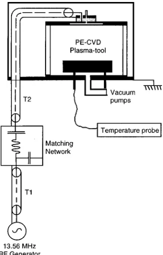
A schematic of the plasma tool is shown in Fig. 1. In Fig. 2 a general representation of the linear elements of the parallel-plate plasma tool is shown. The calculated phase de-lay and inductance at the excitation frequency of the indi-vidual fixed elements and known limits of the variable ele-ments are listed in Table I.
B. Swept frequency measurement circuit
The circuit comprises a Hameg HM5006 combined tracking spectrum analyzer, and an equal ratio arm bridge with provision for a BALUN transformer19 built by
Cam-bridge Analogue Technology Ltd. The Cam-bridge has an open-and short-circuit error of⫾1 dB between 10 and 200 MHz, and a directivity of 38 dB when used with a 50 ⍀matched load at the reference port. A schematic representation of the complete circuit connected to the parallel-plate plasma tool is shown in Fig. 3.
The bridge is used to measure the return loss ratio共RLR (dB)⫽20 log10 Vincident/Vreflected) of the connected plasma
tool with reference to a short-circuit termination at the bridge reference port. The bridge therefore measures the modulus of incident and reflected signals, but does not provide any phase information. The effective frequency range of the measure-ment is determined by the frequency position, the self-resonance frequency of the plasma-tool, and transmission line reflection due to its over extended electrical length.
The swept frequency measurement is performed off line after the plasma has been turned off with the variable ele-ments of matching network unaltered from the complex con-jugate position. To perform the swept frequency absorbance measurement correctly the following steps are followed.
Step 1. A plasma is established in the chamber and the matching network variable elements adjusted to produce a complex conjugate match. This procedure is monitored ac-cording to the incident and reflected power meter readings at the rf generator. The procedure is performed for 5 min to allow heating of the cables to stabilize. This step establishes the measurement of f0.
Step 2. The plasma is extinguished by turning off the rf generator while keeping the position of the variable match-ing network elements fixed 共N.B. for an auto-matching net-work the parking circuit for the variable elements must be turned off兲. Transmission line T1 is now disconnected at the
matching network and replaced directly with the bridge test port. It is important to note that the transmission line from the bridge to the plasma tool must be short. However, the transmission line from the bridge to the short circuit that defines the reference plane must be adjusted to provide a maximum return loss ratio when the initial measurement is
FIG. 2. A general representation of linear elements of the rf electrical circuit contained in the parallel-plate plasma-tool.
FIG. 1. A schematic representation of a PD80 capacitively coupled plasma-tool.
TABLE I. Calculated phase and reactance of fixed value individual ele-ments at the fundamental and known limits of the matching network vari-able elements for the plasma-tool.
Plasma-tool
T1
Phase delay
共degrees兲 C1 共pF兲
C2 共pF兲
L1 共H兲
T2
Phase delay
共degrees兲 Intact
Ci
共pF兲
performed in step 3. The remaining bridge input and output ports are connected to the tracking generator and spectrum analyzer, respectively.
Step 3 establishes fmand the return loss ratio. The swept frequency measurement of the plasma tool is performed, with the spectrum analyzer set to a frequency range of 10–20 MHz and a resolution bandwidth of 250 kHz. The return loss ratio is measured on the y axis of the spectrum analyzer as a function of swept frequency along the x axis. When the plasma tool resonates with the bridge, the reference termina-tion is balanced with the plasma short circuit. This conditermina-tion appears as an absorbance maximum (RLRmax, or minimum
voltage standing wave ratio共S兲, where a value of 0 dB RLR
⫽infinite S兲. For all experimental data reported here, the short-circuit reference plane was l⫽2 cm from the bridge.
III. RESULTS AND DISCUSSION
To illustrate the measurement technique, values of Cp for He, Ne, Ar, O2, N2, and N2O plasmas have been ob-tained as a function of both incident power共50–100 W兲and pressure共0.02–0.8 mbar兲. The gases were chosen to provide a range of monatomic and polyatomic gases with differing ionization potentials.
For clarity the experimental results are presented in three sections. Section A describes the self-resonance frequency for an empty chamber and the radiative losses of the plasma tool under Ar plasma conditions. Section B describes the swept frequency absorbance measurement for He, Ne, and Ar plasmas. Section C describes the experimental results for N2, O2, and N2O plasmas.
A. Self-resonance frequency and radiative losses
With the matching network removed, the resonant fre-quency of the chamber and connecting transmission line T2 was measured to be 19.2 MHz with a return loss ratio of
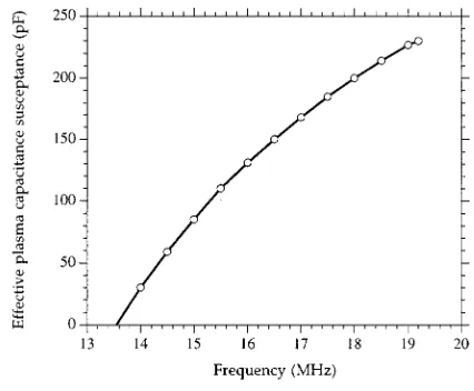
⫺20⫾1 dB and a 3 dB bandwidth of⬃1.5 MHz. The result of this measurement is shown as a solid line in Fig. 4. From a knowledge of Ci⫽230 pF⫾5%, a series inductance value of Li⬃0.3H⫾5% is obtained from Eq.共2兲. Knowing that the plasma tool must resonate at the fundamental frequency of 13.56 MHz under plasma conditions with a capacitance of Cm⫹Cp⫹Ci, a capacitance versus frequency ( fm) calibra-tion in terms of Cp can thus be obtained. This calibration is shown in Fig. 5.
A radiative energy loss measurement was performed on the plasma tool to ascertain the effect of the substrate heater and temperature measurement circuits used to maintain el-evated temperatures of the grounded electrode during PECVD. A second indication of the radiative energy loss was obtained using a Marconi TF975 wavemeter placed at a fixed distance共0.5 m兲from the plasma tool. The position of the attached probe is shown in Fig. 1.
The results of the two swept frequency absorbance mea-surements are shown in Fig. 4 for a 50 W Ar plasma at a chamber pressure of 0.05 mbar. It can be seen that the clean electrode data has an asymmetrical absorbance spectrum with a 3 dB bandwidth of 3.5 MHz centered at fm
⫽16.2 MHz共RLR⫽⫺30⫾1 dB兲. The absorbance asymmetry is characterized by the lower and upper frequency minimum RLR values共i.e., lower frequency limit⫽14.4 MHz, and up-per frequency limit⫽18.8 MHz兲. For these conditions the
FIG. 3. A schematic representation of the swept frequency absorbance mea-surement circuit connected to the parallel-plate plasma-tool.
FIG. 4. Swept frequency absorbance measurement of plasma-tool self-resonance and measurement of fmfor a 50 W Ar plasma for both a clean electrode and with probes attached to the ground electrode.
radiative energy loss as represented by the wavemeter detec-tor current reading was in the region of 2–4A cm⫺2.
The third curve in Fig. 4 represents the same Ar plasma condition with a heater controller and temperature probe at-tached. Under these false plasma matching conditions, fm has now increased to 16.5 MHz 共RLR⫽⫺24⫾1 dB兲, with the upper frequency maximum extended beyond 20 MHz at a RLR of ⫺10⫾1 dB. This extended absorbance region now defines the electromagnetic radiative energy loss from the plasma via the attached probes into free space. The radiative energy loss is confirmed by a wavemeter reading of 50
A cm⫺2. Under these conditions 共or matching into a low impedance discontinuity兲the minimum reflected power has a poor Q and is easily mistaken for the plasma conjugate po-sition. This measurement illustrates the clinical use of the self-resonance absorbance measurement in defining the en-ergy loss associated with the plasma-tool configuration and the need for careful rf design when close-coupled probes are used.
B. Monatomic He, Ne, and Ar
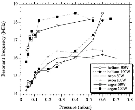
The plasma-tool frequency response to varying ion mass and ionization potential 共He, Ne, and Ar兲 as a function of pressure 共0.02–0.8 mbar兲 at incident powers of 50 and 100 W is reported in this section and shown in Fig. 6.
The values of fm for the helium plasma are seen to in-crease linearly from 14.3 MHz (Cp⫽20 pF) to 18 MHz (Cp⫽200 pF) throughout the pressure range. The data spread suggests that there is no power dependency.
The neon plasma fmcurves exhibit similar low pressure behavior to the He plasma. Above 0.25 mbar the effective capacitance of the Ne plasma becomes a stable value of 16 MHz (Cp⫽130 pF). The results also indicate that there is no change in the dissipative nature of the Ne plasma between 50 and 100 W.
The argon plasma fmdata are seen to increase with pres-sure from 0.02 to 0.2 mbar, above which fmlevels to a value
of ⬃18 MHz (Cp⫽200 pF). As with the neon data, there is no change in the dissipative nature of the argon plasma be-tween 50 and 100 W.
The comparative capacitance data for these monatomic gases shows that Cp scales as the inverse of the gas ioniza-tion potential. At the lowest pressure 共0.05 mbar兲 Cp in-creases from a value of 20 pF共which approximates the intact electrode separation capacitance兲. In the high pressure range
共around 0.7 mbar兲helium does not exhibit the same pressure dependency as neon and argon plasmas. The high pressure behavior is likely to be linked to the high ambipolar diffu-sion rate of helium 共588 cm2s⫺1Torr兲, which is four and eight times larger than neon and argon,20respectively.
The effective plasma capacitance data for argon is of the same order of magnitude as that reported by Roth,18Miller,7 and Viera,21although Miller’s capacitance data is higher by a factor of 4. This discrepancy is likely to be due to the differ-ence in geometry of the two plasma tools共the reported GEC reference cell has two 10 cm diameter parallel-plate elec-trodes separated by 2.54 cm兲. We report the total capacitive contribution of the plasma without differentiation between the plasma sheaths. Our results, however, are in good agree-ment with Bushman, Edgar, and Trachtenberg who reported an effective capacitance of 200 pF for a 0.133 mbar 共100 mTorr兲CF4H2/Ar plasma in a Semi Group reactive ion etch
system.
C. Diatomic O2, N2, and triatomic N2O
In this section the plasma-tool frequency response to the chemical nature of nonpolar diatomic O2 and N2 and polar
triatomic N2O (D⫽0.17) is compared to monatomic argon.
For these gases, low-energy dissociation/ionization and elec-tron attachment dissociation are important fragmentation pathways.
In Fig. 7 the swept frequency absorbance measurements of 50 W Ar and N2O plasmas at a fixed chamber pressure of
0.05 mbar are shown. The comparative data indicate that the
FIG. 6. Frequency response of matching network to 50 and 100 W He, Ne, and Ar plasmas as a function of pressure共mbar兲.
FIG. 7. Swept frequency measurement of 0.05 mbar Ar, and N2O plasmas at
average fmvalue for the N2O plasma is some 2 MHz共
effec-tive capacitance⫽50 pF兲lower than the Ar plasma.
A systematic investigation of fm for O2, N2, and N2O
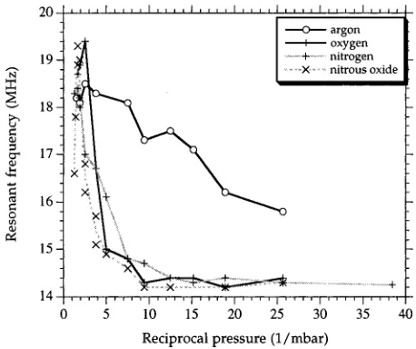
plasmas as a function of pressure 共0.02–0.8 mbar兲and inci-dent rf power共50 and 100 W兲has been performed. The result of these experiments are shown in Fig. 8共50 W兲, and Fig. 9
共100 W兲. In each case fm is plotted as a function of 1/P
共1/mbar兲to reveal its low pressure origin.
In Fig. 8, the fm values for N2, O2, and N2O plasmas
are shown to have similar pressure dependencies, peaking at 0.5 mbar 共2 mbar⫺1兲. The magnitude of each peak is in-versely proportional to ionization potential, with the N2O
plasma fm value reaching the same value as that for the Ar plasma. Below 0.05 mbar all three plasmas reach an isotopic value of 14.3 MHz (Cp⫽30 pF), mirroring the helium and neon plasma data. At these low pressures the plasma sheath thickness is at a maximum and Cpapproximates the intrinsic capacitance of the plasma-tool electrodes.
(⌬Cp⫽74 pF).
The comparative capacitance data for the series of gases reported here indicate that for monatomic gases Cp scales with the inverse of the gas ion ionization potential, whereas for diatomic and polyatomic gases Cp is determined by the incident power. These results may be interpreted in terms of the increased availability of dissociation pathways for di-atomic and polydi-atomic molecules.
IV. CONCLUSIONS
An ex situ off-line swept frequency absorbance measure-ment of a parallel-plate plasma tool has been described. The measurement technique factors in all the contributions from the plasma tool and the transmission line. The self-resonance frequency, radiative energy loss, and plasma-tool distributed intrinsic capacitance can be evaluated. The measurement technique allows for electromagnetic compatibility pre-compliance testing of the plasma tool, plus modification of the matching network and chamber to a specific process gas which is characterized by its effective plasma capacitance. The results also show that plasma tools intended for a wide range of processes should be tested with gases of different ionization potential, mass, and electronegativity across a pressure range from the lowest possible strike pressure to at least 0.5 mbar to ensure adequate range in the matching net-work. The technique is also useful for detecting ‘‘false matches’’ in which a minimum in reflected power at the matching network is due to transmission line reflections rather than a consequence of optimum power transfer to the plasma.
ACKNOWLEDGMENTS
The authors are grateful to Dr. Nina Thornhill at UCL, and Mike Cooke of OPT for helpful discussions regarding applications of the technique.
1J. S. Logan, N. M. Mazza, and P. D. Davidse, J. Vac. Sci. Technol. 6, 120 共1969兲.
2A. J. van Roosmaien, J. Appl. Phys. 42, 416共1983兲; A. J. van Roosmaien,
W. G. M. van den Hoek, and H. Kalter, ibid. 58, 653共1985兲.
3M. A. Sobolewski, J. Vac. Sci. Technol. A 10, 3550共1992兲; M. A.
Sobo-lewski, J. Res. Natl. Inst. Stand. Technol. 100, 341共1995兲.
4S. Bushman, T. F. Edgar, and I. Trachtenberg, J. Electrochem. Soc. 144,
721 共1997兲; N. StJ. Braithwaite, Plasma Sources Sci. Technol. 6, 133
共1997兲.
5P. J. Hargis et al., Rev. Sci. Instrum. 65, 140共1994兲.
6C. Garvin, D. Grimard, J. W. Grizzle, and B. E. Gilchrist, J. Vac. Sci.
Technol. A 16, 595共1998兲; H. M. Park, C. Garin, and J. W. Grizzle, J. Electrochem. Soc. 145, 4247共1998兲.
7P. A. Miller, H. Anderson, and M. P. Splichal, J. Appl. Phys. 71, 1171 共1998兲; P. A. Miller, L. A. Romero, and P. D. Pochan, Phys. Rev. Lett. 71, 863共1993兲.
8
I. Batty, M. Cooke, and V. J. Law, Vacuum 52, 509共1999兲.
9
J. W. Butterbaugh, L. D. Baston, and H. H. Sawin, J. Vac. Sci. Technol. A 8, 916共1990兲.
FIG. 8. Frequency response of matching network to 50 W Ar, O2, N2, and
N2O plasmas as a function of 1/pressure共1/mbar兲.
FIG. 9. Frequency response of matching network to 100 W Ar, O2, N2, and
10E. Gogolides, J-P. Nicolai, and H. H. Sawin, J. Vac. Sci. Technol. A 7,
1001共1989兲.
11B. M. Annaratone, V. P. T. Ku, and J. E. Allen, J. Appl. Phys. 77, 5455 共1995兲.
12C. M. Horwitz, J. Vac. Sci. Technol. A 1, 60共1983兲. 13
M. Ardehali and H. Matsumoto, Jpn. J. Appl. Phys., Part 1 32, 3029
共1993兲.
14D. S. Burch and R. Geballe, Phys. Rev. 106, 183共1957兲. 15N. E. Bradbury and H. E. Tatel, J. Chem. Phys. 2, 835共1934兲. 16J. W. Coburn and E. Kay, J. Appl. Phys. 43, 4965共1972兲.
17V. J. Law, Vacuum 51, 463共1998兲. 18
W. C. Roth, R. N. Carlile, and J. F. O’Hanlon, J. Vac. Sci. Technol. A 15, 2930共1997兲.
19Reference Data for Engineer: Radio, Electronics, Computer and
Commu-nications, edited by E. C. Jordan, 7th ed.共H. W. Sams, Indiannapolis, 1968兲, pp. 12.33–35.
20
Basic Data of Plasma Physics, edited by S. C. Brown共AIP, New York, 1994兲, pp. 1–26.
21G. Viera, J. Costa, F. J. Compte, E Gracia-Sanz, J. L. Andujar, and E.