Volume 3, No. 5, Sept-Oct 2012
International Journal of Advanced Research in Computer Science
RESEARCH PAPER
Available Online at www.ijarcs.info
ISSN No. 0976-5697
Image Processing Based Automated Border Surveillance
Ankur Srivastava*
Center for Advanced Training in Earth System Sciences and Climate
Indian Institute of Tropical Meteorology Pune, India [email protected]
Akhilesh Tripathi
Department of Electronics and Instrumentation SRMCEM Lucknow, India
Chetan Swaroop Sharma
Department of Electronics and Instrumentation SRMCEM Lucknow, India
Abstract: In this paper, the design of an automated border surveillance system is presented. The system consists of two robots and the associated hardware. The system detects an intrusion by an enemy, in turn eliminates the intruder and also sounds an alarm. When there is no intrusion, the robots patrol in their region. The hardware part includes a webcam (for image acquisition), a computer system running MATLAB (for image processing), a central control unit (consisting of ATMEGA16 microcontroller, RF modules and their associated circuitry), and the two robots. The prototype has been prepared and tested in real time. It is working as proposed by the objective of the paper.
Keywords: Webcam,MATLAB, ATMEGA16 microcontroller, RF modules.
I. INTRODUCTION
The paper aims at developing an automatic system for checking border infiltration, deviating from the conventional manually controlled systems. It is an image processing system using MATLAB. A system of two robots has been developed, that are wirelessly controlled by a microcontroller. The microcontroller is interfaced to a computer system via the serial port. A MATLAB program running on the computer acquires video from an overhead camera, processes it, and instructs the microcontroller to move the robots as per the logic of the program. Whenever an enemy crosses the defined logical border, the two robots attack it, sound an alarm, and produce an alert on the watch tower. Else, they patrol their own region.
II. FEASIBILITY
A. Technical Considerations:
The applicability of the system to real life situations is dependent largely upon the availability of an image acquisition source, such as a satellite camera, or a camera mounted on an Unmanned Aerial Vehicle (UAV).
With regards to this, sophisticated technologies do exist. Secondly, dedicated image processing software needs to be developed. The rest of the systems required already exist.
Radio controlled military vehicles, tanks, etc., have been in use for quite some time. The only requirement is to interface them to a central control unit.
More complex algorithms and software will be needed for implementation of such a system as only the basic RGB colors have been used for identification of the enemy and friend robots.
B. Economic considerations:
This might prove to be a roadblock in the development of such a system.
Extensive research and development will be required to develop a fool proof system that might take years.
Also, the cost of image acquisition from satellites is high. The security of the data received needs to be ensured.
The rest of the systems do exist. These include radio controlled robots, missile guidance systems, etc.
However, in the long run, the cost of human life is far greater than the narrow monetary considerations. Thus, the system will prove to be cost effective in the monetary aspect, and more than that, the humane aspect.
III. PROPOSEDMETHODOLOGY
Figure 1: Complete block diagram of the proposed system
A. Image processing in MATLAB [1]:
[image:2.612.100.224.388.481.2]A sample image of the arena is shown in figure 2 below:
Figure 2: Sample RGB image of the arena
The red colored object in the image is the enemy, while the two blue colored objects are the friend robots. The white spots depict a weapon that has been placed under the spot.
The objects are differentiated on the basis of colors. The two friend robots have different sizes and hence areas, which is used to differentiate them.
A code is written in MATLAB that extracts the red pixels, replaces them with white, and also replaces all the background pixels with black to give a binary image shown below in figure 3.
Now MATLAB has built in subroutines to compute the centroid, area, perimeter, etc. These parameters are used by the program to achieve the proposed objective.
B. Removing Noise:
The binary image obtained from real world has quite a lot of noise.
Edges need to be smoothened, tiny dots scattered here and there must be removed so that some countable number of objects to work upon are left. Several functions available in MATLAB help in noise removal. Some of them are:
a. imclose( ): Performs morphological closing operation. It fills in the gaps between two objects and smoothens the edges. The degree and type of smoothening and joining depend on the structuring element, i.e., the basic shape which is used to perform the operation. The structuring element can be a disk, a diamond, a line, etc. To create a structuring element, we use strel() function. For example,
>> se=strel('disk',5); % a disk of radius 5
>> bw=imclose(bw,se); %Perform the closing operation on original image itself
b. imfill( ): Removes holes from the image. Holes are background pixels surrounded by foreground (image) pixels.
>>bw=imfill(bw,'holes');
Now we need to remove the spatters. For that we can use the function imopen().
c. imopen( ): Morphologically opens the image.
[image:2.612.104.225.624.714.2]Ankur Srivastava et al, International Journal of Advanced Research in Computer Science, 3 (5), Sept –Oct, 2012, 149-153
IV. IMPLEMENTATION
The entire system has two modules: a. Hardware module
b. Software module
The Hardware module again can be subdivided into following parts:
a) Digital camera
b) Max232 module(through UART cable) c) Main control unit
d) RF Modules 1 & 2 e) Power supply module f) Robots
A. Hardware Module Design:
The hardware of the project consists of number of modules integrated together on a board.
a. Digital camera (webcam): In the project we have used Quantum QHM500-8LM(s) webcam which has a resolution of 16 megapixels. It has a high quality CMOS sensor with image control, color saturation, brightness adjust, sharpness control and contrast.
Interface: USB2.0, frame rate: 30 fps (MAX). Lens: f=6.0 F=2.0.
Focus range: 4cm to infinity.
b. MAX232 Module (Serial communication) [2]: For communication between the PC and the microcontroller we have used serial port through an IC module -Max232.
The Max232 IC converts TTL (Transistor-transistor logic) logic signals of PC to CMOS (Complementary metal–oxide– semiconductor) logic used by Microcontroller (Atmega16).
The standard used for serial communication is RS-232 (Recommended Standard 232). It defines the voltage levels that correspond to logical one and logical zero levels. Our PC works on TTL logic with voltage levels ranging from plus or minus 3 to 15 volts, as defined by the RS-232 standard.
Atmega series microcontroller does not work on the voltage levels defined by the RS-232 standard. Hence, a device is required which can convert this voltage level to that of CMOS, i.e., logic 1 = +5V and logic 0 = 0V. This task is accomplished by an IC MAX 232.
c. Main control module [3]: The main control module of the project is the control center. It has an 8 bit microcontroller Atmega16 to which RF modules and display are connected.
The input to the microcontroller is given through DB9 connector through serial port of the PC, via MAX-232 module.
The main control module has the following parts: a) Atmega 16 microcontroller
b) 16*2 LCD
c) 6-0-6 500 mA transformer d) Connection plate
e) RF transmitter modules
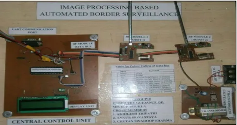
[image:3.612.65.553.382.640.2]The main control unit is shown in figure 4.
Figure 4: Main Control Unit
B. Software Module Design:
Software implementation is an important part of this project. It has again two parts: MATLAB codes & microcontroller codes. The algorithm of image processing is
Figure 5: Flow charts of MATLAB source codes
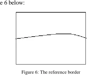
a. Detection of an intrusion: A reference logical border that separates the enemy and friend region is shown in figure 6 below:
Figure 6: The reference border
The pixel X-Y co-ordinates of the reference border have been programmed into the MATLAB code. The centroid of the red region is calculated, compared with reference boundary, and hence, an intrusion detected.
Now, if the enemy has crossed the border, the attack subroutine is called, else, patrol subroutine is initiated.
b. The attack subroutine: This subroutine computes the angle between:
a) The line segment joining the centroids of the enemy and the friend robot, and,
b) The line segment joining the centroids of the enemy and the white spot on the friend robot.
This angle is a measure of the amount by which the friend robot is to be rotated so as to orient its weapon towards the enemy.
As soon as this angle is less than 0.5, the program logic instructs the microcontroller to fire the weapon, thus accomplishing the attack mechanism.
c. The patrol subroutine: There are two friend robots in the arena, hence, the friend region has been sub-divided between them.
If the robot is in its defined region, the program logic instructs it to move forward.
[image:4.612.77.232.513.638.2]Ankur Srivastava et al, International Journal of Advanced Research in Computer Science, 3 (5), Sept –Oct, 2012, 149-153
V. RESULTSANDDISCUSSIONS
The paper aims at developing an automatic system for checking border infiltration, deviating from the conventional systems.
The prototype has been prepared and tested. It is working as proposed by the objective of the system. The two robots are patrolling the prototype war field when there is no intruder, attacking the intruder, sounding an alarm and activating the watch tower upon security breach, as proposed.
The results are as per the objective of the project, though there are certain time lags due to slow processing of the source code on the computer due to limited computational abilities. This needs to be improved by the use of high speed computational devices with dedicated image processing software in the future.
VI. CONCLUSIONS
We take this paper as a stride forward towards the development of sophisticated automatic systems. The project is not bounded by the realms of battlefield scenarios, but in a larger prospect, will apply to every aspect of human life, be it humanoid robots, or other artificially intelligent systems.
Every system has some limitations apart from its advantages. Our project is at preliminary stages of development and hence there are some limitations which need to be overcome in the future.
One of the major limitations of the project is its real world simulation since real world systems are much more complex and dynamic.
Secondly, dedicated image processing software needs to be used, as MATLAB has limited image processing capabilities.
Also, research, development and establishment of such a system will require huge investments.
VII. REFERENCES
[1] Online resource, “Image Processing Toolbox-Documentation”, available online at:- http://www.mathworks.in/help/toolbox/images/
[2] Online resource , “MAX232 Datasheet- Texas Instruments”, available online at:- http://www.ti.com/lit/ds/symlink/max232.pdf