Volume 6, No. 2, March-April 2015
International Journal of Advanced Research in Computer Science
RESEARCH PAPER
Available Online at www.ijarcs.info
An Enhanced Energy Efficient Routing Scheme in Wireless Sensor Networks
R.Mehala
1, Dr.A.Balamurugan
2PG Scholar1,Professor2
1,2Department of Computer Science and Engineering
Sri Krishna College of Technology Coimbatore, Tamilnadu, India
Abstract: Wireless sensor networks (WSNs) offer much promise for target tracking and environmental monitoring. Energy efficient routing in wireless sensor networks has become a challenging research area. Routing algorithms for WSNs are responsible for selecting and maintaining the routes in the network, which ensure reliable and effective communication within limited coverage areas. The energy constraint of WSNs becomes the most important objective of various routing protocol algorithms,where the battery level of each sensor nodes gets reduced during each transmission.The best way is to form an optimal number of clusters using Expectation Maximization clustering method in order to reduce the network congestion problem and to transmit the data to mobile sink which travels using Floyd's algorithm. Another important problem occurs when the mobile sink fails due to loss of energy or hardware requirement.This leads to the overall delay in sending data to the destination.When the sensor nodes reach a particular threshold value,it will transfer the data in a multi-hop manner by using Route-split-Routing algorithm.By selecting Sub management nodes in the particular path can ensure efficient routing to destination.
Keywords: Expectation Maximization, Route-split-Routing, Cluster centroids, Floyd‟s algorithm
I.INTRODUCTION
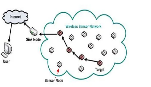
Wireless Sensor Networks (WSN) can be defined as a self configured network formed by large numbers of sensor nodes scattered over a geographical area within a predefined location or randomly deployed. Figure 1.1 shows that sensors are used to collect data from the environment to monitor different types of objects or physical conditions. These sensor nodes can sense, measure, and gather information from the vicinity and transmit the sensed information to the user or information sink. Communication of sensed data from the sensor nodes to the information sink happens to be the main cause of energy depletion in sensor nodes. Recent advances in micro-electro-mechanical systems (MEMS) and highly integrated digital electronics have led to the development of micro sensors. Such sensors are generally equipped with data processing and communication capabilities. The limitation of energy supply makes it indispensable for the sensor nodes to preserve energy and to increase the network lifetime. So, energy minimization is one of the most important topics in the area of WSN research in order to extend the network lifetime during data transmission. These networks offer potentially low cost solutions for an array of problems in both civilian applications and military applications including battlefield tracking, environmental and railway tracks, health care monitoring, wildfire detection, and traffic regulation.
Figure 1.1 Wireless sensor networks
Due to the low deployment cost required for wireless sensor networks, these nodes have simple hardware and complicated resource constraints. Sensor nodes are normally battery-powered and remain stationary after deployment. When a sensor node runs out of energy or power it will no longer provide sensing and data processing. This can lead to a huge data loss in the network due to the routing path re-allocation and failure of sensing and reporting events in the environment. Hence energy consumption has been receiving increased attention in WSN research works. The concept and use of mobile sink has been recently introduced for WSNs in order to improve the overall performance of WSNs as it shifts the burden of energy consumption from the sensor nodes
Routing in sensor networks is very challenging due to several characteristics that distinguish them from contemporary communication and wireless ad-hoc networks. The routing mechanisms consider the characteristics of sensor nodes along with the application and architecture requirements. Almost all of the routing algorithms can be classified as data-centric, tree-based, hierarchical or location-based and there are few distinct ones which is based on network flow or QoS awareness. The effective solution to this issue is to allow mobility for the sink node, so that the sink node will propagate dynamically and there would not be a fixed set of nodes that have to work as a relay agent to the base station.The major drawback of using the mobile sink will lead to the energy depletion when it travels from each sensor node to the base station.If the mobile sink fails or loses its whole energy sensor nodes cannot transmit the sensed data to the base station.It will lead to the overall delay in transmission and increase in energy consumption.In such case multi-hop transmission of data mechanism can be adapted to route data from source to destination by using threshold value.
In this paper we are considering clustering and routing as an important mechanism. Hence for the designing the optimal cluster based routing technique we will consider the following pivotal issues:
1. Cluster formation by considering the balanced load to every cluster.
2. Considering mobility to the base station dynamically to avoid „energy-hole‟[6,7] problem
3. Mobile sink patrols through the cluster centroids and take shortest path to destination to upload the data
4. Routing by Route-split-routing algorithm is used when the mobile sink does not return to the cluster centroids within predefined threshold time
5. Route maintenance is performed by using Sub-Management nodes(SMN) when a link failure occurs in the network
The remaining section of the paper is organized as follows. Section II reviews some related works and its problems. Section III presents the clustering based routing algorithm in WSN. Section IV presents the Overview of Expectation Maximization technique and Route split routing algorithm. Proposed method is presented in Section V.Section VI represents the performance analysis of proposed method. Finally Section VII concludes the paper.
II.RELATED WORKS
Mo Xiaoyan et al.[3] have proposed that the hierarchical approach for the network topology breaks the network into several areas called clusters. Nodes are grouped depending on some parameter into clusters with a cluster head which is responsible for routing the data from one cluster to another cluster head or base stations. Data travels from a lower clustered layer to a higher one. The data still hops from one node to another, but it hops from one layer to another and covers larger distances and moves the data faster to the base station than in the multi hop model [4]. Clustering provides
inherent optimization capabilities at the cluster heads, what results in a more efficient and well structured network topology.
Jiming Chen et al [5] presented a flow control optimization problem for wireless sensor networks with lifetime constraint and link interference in an asynchronous setting is formulated.It is based on the network utility maximization framework, in which a general utility function is used to characterize the network performance such as throughput.A flow control algorithm is a practical method to
successfully deal with congestion control and resource allocation by regulating source transmission rates in response to changes in network conditions.Utility-based Asynchronous Flow Control (UAFC) is the first asynchronous flow control algorithm for wireless sensor networks by which each link estimate the link prices from its interference set and congestion prices from the network.In wireless sensor networks ,because of the broadcast nature of the wireless medium the flows contained in the time and spatial domains for the shared wireless medium are within the interference range of each other.
the nodes and the node‟s transmission power are set as equal. Here routing strategy needs to be controlled and only certain nodes are to be allowed to receive and process the routing request based on the received signal strength, then the overall energy consumption of the network can be minimized and the communication overhead is also minimized. routing in WSN is performed using Floyd‟s algorithm which determines the trajectory of the mobile sink.
A. Clustering
When considering a routing scheme in WSN using the mobile sink, the biggest challenge is used to reduce the energy depletion in the sensor nodes. The energy depletion can be reduced by forming clusters of sensor nodes and then the mobile sink travels around the cluster centroids to collect the sensed data. When forming clusters it should be ensured that no same node should be present in one or more clusters.The sensor node which is present in more than one cluster will transmit the data to the mobile sink frequently by data request flooding message. EM algorithm is powerful and well known method to solve the clustering problem by iteratively calculating the sum of square of distance between every node and cluster centroid, we adopt EM algorithm over the 2-characteristics that distinguish these networks from other wireless networks like mobile ad hoc networks or cellular networks.In a large-scale wireless ad hoc and sensor network, packets are often transmitted via multiple hops to reach their destinations. The hop count, hi, of a node ni is often related to
a particular hop count originator n0 (a sink or a node) and it
measures how many transmissions are needed to send one packet from n0 to ni. The hop count information has been
widely used in the design of many network routing protocols.
C.Trajectory of the mobile sink
After clustering of WSN nodes, we will determine the actual trajectory of the mobile sink. The mobile sink traverses through clusters and aggregate data from various nodes. Since it is possible to increase efficiency by reducing the travelling
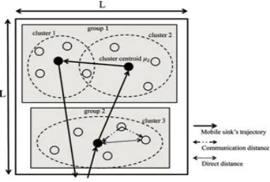
time, it is preferable that the mobile sink traces the shortest sensor nodes are of equal energy at the initial phase.There are two sinks in the proposed system one is the static sink node and other is a mobile sink node[1].The static sink node is placed in the center of the network and in this system there are two mobile sinks. These mobile sinks travels around the cluster centroid to gather data. The cluster centroid gets a data request message from the sensor nodes and forwards the message to one of the mobile sink. When the mobile sink gets message from more than one cluster centroid it forwards to other mobile sink.Figure 4.1 explains the considered network model for the proposed system
Figure 4.1 Network model
B. Clustering phase
The sensor nodes are deployed in a physical environment for monitoring and sensing the data. A large number of sensor nodes of equal energy and mobile sink of higher energy is deployed in the sensing area. At the initial stage, the nodes are scattered and cluster centroid is placed at random locations by using EM algorithm[2].Then the clusters of nodes are formed by calculating the shortest distance between cluster centroid and sensor nodes.The distance is calculated by taking one-hop neighbor from each sensor node to cluster centroids. The responsibility value for each node is measured. The responsibility value refers to the degree of dependence of sensor nodes. Some sensor nodes have lower degree and some nodes have higher degree value.
The nth node‟s value of degree of dependence on kth
cluster is given by following equation.
Distance, Dnk= (2)
on location information of cluster members.Nodes are grouped based on fixed transmission distance.To decide the optimal number of clusters, objective function is defined. The objective function is defined as the sum of required energy of data and data request message transmissions.
Thus the objective function W(K), can be defined as the sum of energy consumption in one cycle of mobile sink
The mobile sink patrols around the cluster centroids to gather the data.The trajectory path of the mobile sink is determined by using shortest path algorithm like Floyd‟s algorithm.Each of the cluster centorid in the network is aware of their neighboring centroid.Each sensor nodes in the network contains a routing table which contains the routing information of the other sensor nodes.The routing information consists of source and destination address,hop count value,threshold value indicate the time for which the mobile sink should collect data from the particular sensor node.When the time reaches the threshold value,the sensor node does not wait for the mobile sink for giving their data,instead the sensor nodes takes multi-hop route to destination.This ensures that the battery level of sensor nodes may exhaust soon when transmitting data.To reduce the energy consumption of sensor nodes,Route split Routing method is used.A subroute management node(SMN) is selected which has higher energy in the particular path.
E.Selection of SMN Node
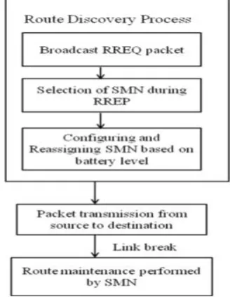
Figure 4.2 explains the architecture of RSR algorithm.If the Source node does not have path to Destination node it initiates Route discovery process by broadcasting RREQ packet. The destination node on receiving RREQ packet initiate RREP packet with hop count initially set to 0. RREP packet is unicasted and each time hop count gets incremented by 1. SMN hop count interval is set to some predetermined interval. Using Route Split Routing the routes are divided into segments. The node checks its residual battery level and if it has the sufficient battery level then node becomes SMN. Otherwise, the above process is repeated for next hop node and reassignment is performed. The node which is selected as SMN sends a RREP packet so that other nodes in the path create a SMN table with fields including Node ID, Node Address, SMN Address , Segment number,hop count,energy level. Destination node and source node acts as SMN by default. As the RREP reaches source node, other node in the established path know about its next SMN.
Figure 4.2 shows the system architecture of RSR
F. Performing Link Repair
After the selection of SMN node based on its residual battery level, each node in the segment maintains its SMN address for that segment which is used for performing link repair. If there is a link break between two nodes because of mobility or low battery level, the repair RREQ packet is initiated by its upstream node with destination address as its SMN node address and repair is performed for that segment. The destination node on receiving RREQ replies with repair RREP packet. The node on receiving repair RREP packet assumes provide assurance against variations of dynamical battery level changes in various environments, we conducted simulation experiments.Table 5.1 shows the parameters for the simulation experiments.In the experiments,the number of the source and destination nodes does not change. The pause time of a node in the random waypoint model is 0. For the MAC layer protocol, we employ IEEE802.15.4 . The number of nodes and field size are fixed and the SMN interval is three. The threshold of SMN battery levels is 80 joules.Performance of the system can be evaluated by QOS metrics like bandwidth, throughput, number of nodes and data accuracy, overall delay,overhead of messages,packet delivery ratio,packet drop and packet loss.
5.1 PARAMETERS FOR EVALUATION
The parameters considered used to measure the performances of the routing in the network are,
Throughput
Throughput= No of bytes transmitted to destination
Simulation time
Average End to End Delay
Average End to End Delay is the average of time elapsed from the delivery of a data packet from the source to the arrival of the data packet at the receiver.
Packet Delivery Ratio
The (PDR) is defined as the ratio between the numbers of data packets received by the destination to the number of data packets sent by the source.
Energy Consumption during Transmit mode
A node is said to be in transmission mode when it sends data packet to other nodes in network
Energy consumption during reception mode
When a node receives a data packet from other nodes then it said to be in Reception Mode
5.2 SIMULATION RESULTS AND DISCUSSION
We evaluated the simulation results by generating various graphs and a comparison was made between AODV and RSR methods.
End to End Delay
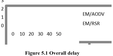
Figure 5.1 indicates the end to end delay measured using RSR and AODV algorithm
0 1 2 3
0 10 20 30 40 50
EM/AODV
EM/RSR
Figure 5.1 Overall delay
X-axis=Time in seconds Y-axis=Overhead
Table 5.1 shows the parameters for the simulation experiments.
Parameters Values
Area of Simulation (1500x1500)
Nodes number 32
Types of Routing protocol AODV/RSR
Type of the MAC 802.15.4
Internet protocol type TCP
Antenna Model Omni directional
Mobility Random Waypoint
Battery model Micaz
Energy 60 Joules
Simulation time 300s
Total no of packets sent 100
Size of data packet 70
Throughput
Figure 5.2 indicates the throughput measured using RSR algorithm
Figure 5.2 Throughput
X-axis=Time in seconds
Y-axis=Throughput(%)
Packet Loss
Figure 5.3 indicates the packet drop measured using RSR and AODV algorithm
Figure 5.3 Packet drop
X-axis=No of nodes
Y-axis=No of packets
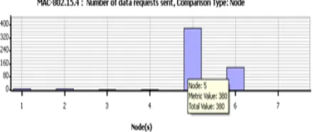
No of data requests Sent
Figure 5.4 Data request sent
No of data requests received
Figure 5.5 indicates the number of data request packets received between each sensor nodes
Figure 5.5 Data request received
Energy consumed in transmit mode
Figure 5.6 indicates the energy consumed in each sensor nodes during transmisssion
Figure 5.6 Energy model
Energy consumed in received mode
Figure 5.7 indicates the energy received in each sensor nodes during transmisssion
Figure 5.7 Energy model
VI. CONCLUSION
The decisive aim of a routing protocol to design is to extend the lifetime of the network by keeping the sensors alive for a maximum time. Since power depleted on transmission is very high compared to that of sensing, the routing algorithm should be implemented to reduce energy consumption while transmitting data.Thus by using mobile sink energy of the sensor nodes can be increased but when mobile sink fails the sensor nodes takes the shortest path to destination in a multi hop manner which reduces the overall delay and increases the network lifetime.
VII. REFERENCES
[1] Xiaobing Wu , Nanjing Univ., Nanjing Guihai Chen (Aug. 2007),“Dual-Sink: Using Mobile and Static Sinks for Lifetime Improvement in Wireless Sensor Networks “,Computer Communications and Networks, ICCCN 2007, pp 1297 – 1302.
[2] Daisuke Takaishi, Hiroki Nishiyama, Nei Kato, and Ryu Miura, "On the Effect of Data Request Message Flooding in Dense Wireless Sensor Networks with a Mobile Sink," IEEE 78th Vehicular Technology Conference (VTC 2013 Fall), Las Vegas, Nevada, USA, Sep. 2013.
[3] Mo Xiaoyan (2006) „Study and Design on Cluster Routing Protocols of Wireless Sensor Networks‟, Dissertation, Hang Zhou, Zhe Jiang University. [4] Mu Tong (2010) „LEACH-B: An Improved LEACH
Protocol for Wireless Sensor Network‟, IEEE
[5] C. Jiming, X. Weiqiang, H. Shibo, S. Youxian, P. Thulasiraman, and S. Xuemin, (September 2010),‟Utility-based asynchronous flow control algorithm for wireless sensor networks‟, IEEE Journal on Selected Areas in Communications, vol. 28, no. 7, pp. 11161126.
[6] T.H. Kim, H. Adeli, “Dynamic routing for mitigating the energy hole based on heuristic mobile sink in WSNs”, AST/UCMA/ISA/CAN 2010, LNCS. 6059, Heidelbarg 2010, pp. 159-174.
[7] J. Wang, Y. Yin, J. Kim, S. Lee, “A mobile sink based energy efficient clustering algorithm for WSNs”, IEEE-CIT, Chengadu, 2012, pp. 678683.
[8] Balaswamy Ch., Naga Prakash K., Hima Bindu Ch., (2011), „An Energy Efficient Routing Protocol based on Periodic Route Discovery for Mobile Ad Hoc Networks‟, International Journal of Next-Generation Networks, Vol. 3 No. 1 pp. 45-51.
[10] Lalitha V., Rajesh R S., (2014), „AODV_RR: A Maximum Transmission Range Based Ad Hoc on-Demand Distance Vector Routing in MANET‟, Springer Science, Vol. 45 No. 6 pp. 1-16.
[11] Senouci S M., Naimi M., (2005), „New routing for balanced energy consumption in mobile ad hoc
networks‟, Proc. Second ACM International Workshop on Performance Evaluation of Wireless Ad hoc, Sensor, and Ubiquitous Network, PE-WASUN, New York: ACM, Vol. 2 No. 5 pp. 238–241.