DOI: http://dx.doi.org/10.26483/ijarcs.v8i8.4683
Volume 8, No. 8, September-October 2017
International Journal of Advanced Research in Computer Science
RESEARCH PAPER
Available Online at www.ijarcs.info
ISSN No. 0976-5697
DESIGNING OF NOVEL SECURITY BASED WDM-PON SYSTEM BY USING
BROADBAND LIGHT SOURCE (BLS)
Simrandeep Singh Thapar
Associate Professor, Deptt. of Computer Applications ACET, Amritsar
Punjab, India
Himali Sarangal
Assistant Professor, Deptt. of ECE GNDU RC Jalandhar
Punjab, India
Abstract: The Optical network plays an important role in the communication field because of its inherent benefits. It reduces capital and operational cost and also supports a wide range of new and high-bandwidth applications. The most effective and promising technique used in the Optical communication is WDM-PON (Wavelength division multiplexing passive optical network). WDM-PON provides relatively higher bandwidth security, high speed and makes communication reliable but security is the main issue on which various attempts are made to increase this security level in WDM-PON. In this paper, a 20 X 10 Gbps self-protected WDM-PON architecture is used to enhance the security level by using the Broadband light source (BLS). The results of this study show that physical security can be achieved through Broadband light source in which each frame is transmitted at a unique wavelength and secured data is obtained at the output. The Performance analysis is performed by using the Optisystem software.
Keywords: Fiber to the home (FTTH), Fiber to the building (FTTB), Wavelength Division Multiplexing Passive Optical Network (WDM-PON), Optical Line Terminal (OLT), Optical Network Unit (ONU), Broadband Light Source (BLS).
1.INTRODUCTION
A huge information measure capability is provided by the optical access network which incorporates several applications like Fiber to the house (FTTH), Fiber to the building (FTTB). PON is a good and promising technique accustomed implement the FTTH. With the assistance of various number techniques, an outsized variety of users is often transmitted on one fiber. WDM is the successful technique within which capability of a fiber is multiplied on the idea of the magnitude. It is troublesome to implement all the changes on TDM (Time-division multiplexing) attributable to this WDM-PON is most popular over the TDM PON [1]. Higher information rates are often achieved by victimization WDM-PON system and conjointly it provides higher information measure to the system [2]. APD receiver provides comparatively high responsivity still as high quantum potency as compared to the PIN Photoreceiver. Bessel filter shows higher performance in terms of Minimum BER and most Quality issue [3]. Under the normal and protection mode operations, evaluation of WDM-PON is done in both upstream and downstream directions. The performance of scalable self-protected WDM-PON shows the good result in comparison to other PON architecture [4]. Enhanced security system can be used in WDM-PON with the help of hybrid approach [5]. In the Hybrid WDM/TDM PON, Dynamic bandwidth and wavelength allocation (DBWA) algorithms are implemented to solve the traffic originated by end users equipped with transceivers with different characteristics [6]. WDM-PON uses passive components which reduce the maintenance cost, as well as best performance, is achieved in the system [7]. Non-return to zero (NRZ) scheme is used in the realization of the WDM-PON and shows the good result on fiber length of 20-100 km [8]. As compared to TDM PON technology, WDM-PON supports a large number of users
Optical Amplifier) can be used in WDM-PON for better performance [10].A better result can also be obtained through Low pass Bessel filter in the WDM-PON system [11]. Different amplifiers used in WDM-PON in which EDFA is proved to be the best amplifier because it has less crosstalk associated with it and hence, a less chromatic dispersion is present in the system. It has also shown best performance in terms of the maximum quality factor and minimum BER value [12].
2.MODELDESCRIPTION
[image:2.595.318.554.77.148.2]A desirable approach for security improvement in PON has been achieved through the utilization of WDM-PON. A WDM-PON theme provides point to point link between OLT and ONU with a novel wavelength. The WDM-PON system essentially consists of 3 components that are a transmitter, transmission medium and receiver section. The diagram of the WDM-PON security system is shown in Fig. 1. The transmitter section consists of 20 transmitters and all the data from these transmitters are multiplexed so circulated by victimization the Broadband light. WDM-PON uses multiple wavelengths within the network to hold the info with the assistance of white light in operation at 193.1 rates within the downstream direction. The main purpose of BLS is to inject the signal to lock the OLT.
Fig. 1 Block Diagram of 201x10 Gbps WDM-PON security system
[image:2.595.37.279.252.354.2]It also makes single wavelength to move from input to output port. The Data rate of 10 Gbps is used in the OLT and Single mode fiber of length of 70 km is used to carry the data. All the parameters which are used for designing the 20 X 10 Gbps WDM-PON system have been mentioned in a table given below.
Table 1. Parameters used in designing the WDM-PON in the downstream direction
Parameters Values
CW Laser Frequency 193.1THz (Downstream)
Data Rate 10 Gbps
Line coding scheme NRZ pulse generator
Detector APD Detector
Filter Low Pass Bessel Filter
Power 0 dBm
Frequency Spacing 100 GHz
White Light Source 193.1 THz
Channel spacing of 100GHz is used to avoid the disturbances occur among the adjacent frequencies. Non-Return to Zero (NRZ) is a line coding scheme used in WDM transmitter in which binary value ‘1’ is represented by a positive voltage and ‘0’ is represented by a negative voltage. The pulses have more energy than the RZ code. It requires only half the bandwidth than another coding.
Fig. 2. Block diagram of ONU
At the receiver side, data is demultiplexed with the help of demultiplexer. Fig. 3 shows the block diagram of ONU (Optical network unit). ONU consists of a detector and low pass Bessel filter which is used to convert optical signal back to electrical form. APD detector is preferred over the PIN detector. Since, It has much higher sensitivity and responsivity because of avalanche effect in its intrinsic region to create an electrical gain. The Output from APD detector is passed to low pass Bessel filter. Low pass Bessel filter has a good phase response and also it has the best step response with minimal overshoot or ringing, So, a uniform time delay within pass band is attained. Along with that Bessel filter has a slower initial rate of attenuation beyond the pass band compared to Butterworth and other filters. The electrical signal from the filter is passed through the regenerator. The output is obtained by using the BER analyzer at the receiver end.
3.RESULTSANDDISCUSSIONS
[image:2.595.33.271.487.644.2]This paper analyzes the performance of 20 users of WDM-PON in the downstream direction with the help of white light source to enhance the security level. Signals having multiple wavelengths is used to carry the data. The WDM-PON model has been verified by using optical spectrum analyzer which indicates that data is secured on each channel. A 10Gbps signal source was given in OLT by using optisystem. Data from different transmitters are passed through the bi-directional circulator. A single mode fiber of length 70 km is used to carry the data and then data is demultiplexed to each destination ONU using WDM demultiplexer.
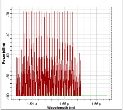
[image:2.595.339.536.569.744.2]The transmission spectrum of 20 Channels WDM-PON before demultiplexer is shown in above Fig. 3. The responsivity of WDM-PON network is 1 A/W and dark current used is 10nA in the system. It is clearly visible that signals having multiple wavelengths are separated on the basis of their respected frequencies and accepted by each ONU. The output is obtained and analyzed with the help of BER analyzer at the receiver end.
(a)
(b)
(c)
(d)
Fig. 4 (a) Power spectrum of ONU 1 ; (b) Power spectrum of ONU 2 ; (c) Power spectrum of ONU 3; (d) Power spectrum of ONU 4
We have taken an optical spectrum of 4 ONUs and results of these ONUs defines that each signal is received at particular wavelength without interfering with another wavelength. It is assured from the Fig. 4 (a) (b) (c) (d) that specific user has specific frequencies and all other frequencies are filtered out at the demultiplexer. Adjacent channels have shown a small amount of signal power in WDM -PON at each ONU but their level is below the threshold level of the receiver.
It is clearly seen from the results that the good quality signal received at each ONU. Also, we have measured the BER and quality factor in this simulation environment which corresponds to mean values. The data rate of 10 Gbps is used in this evaluation. Single mode fiber having a length of 70 km is used to carry the data preferred over the multimode fiber to avoid intermodal dispersion which signifies longer rate of transmission due to less attenuation and signal remains stronger for the considerable length.
[image:3.595.327.549.55.460.2]Table 2: Analysis of NRZ coding at 10 Gbps data rate of 20 ONUs
Max. Q Factor Min. BER Eye height Threshold
ONU 1 5.69686 6.0456e-009 4.05554e-005 5.63937e-005
ONU 2 5.63695 8.4307e-009 3.98831e-005 5.54293e-005
ONU 3 5.97299 1.15183e-009 4.22624e-005 5.73672e-005
ONU 4 6.0152 8.86476e-010 4.29447e-005 5.59181e-005
ONU 5 5.51442 1.71486e-009 3.96445e-005 5.54528e-005
ONU 6 5.92235 1.55229e-009 4.24965e-005 5.55713e-005
ONU 7 5.90644 1.72709e-009 4.20817e-005 5.63409e-005
ONU 8 5.66185 7.40682e-009 4.10115e-005 5.75235e-005
ONU 9 5.51166 1.74449e-009 3.90982e-005 5.50997e-005
ONU 10 5.64018 8.19547e-009 4.02327e-005 5.2231e-005
ONU 11 6.02358 8.3835e-010 4.3268e-005 5.56777e-005
ONU 12 6.15586 3.66618e-010 4.42411e-005 5.50572e-005
ONU 13 5.76654 3.94902e-009 4.19902e-005 5.47342e-005
ONU 14 5.7335 4.78137e-005 4.0696e-005 5.3073e-005
ONU 15 5.75898 4.12900e-005 4.11818e-005 5.3952e-005
ONU 16 6.29241 1.54149e-010 4.57504e-005 5.62108e-005
ONU 17 5.8339 2.6626e-009 4.24124e-005 5.46424e-005
ONU 18 6.00812 9.09632e-010 4.40841e-005 5.37551e-005
ONU 19 6.01505 8.79338e-010 4.40889e-005 5.61846e-005
ONU 20 6.23974 2.14946e-010 4.60218e-005 5.60447e-005
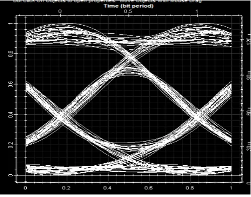
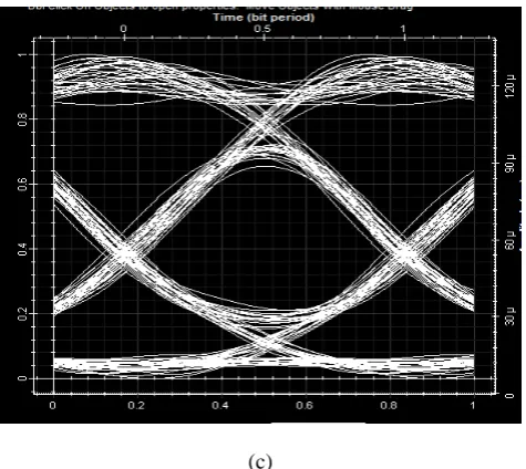
The eye pattern technique is used for assessing the data handling capabilities and evaluating the performance of an optical system. The width of the eye opening defines the time interval over which the signal is received without any inter symbol interference. The Fig. 5 (a,b,c) shows the eye pattern of 20 receiver ONUs and specifies that the data is received without interfering with other signals. These results are obtained for WDM-PON system at 10Gbps data rate and show that there is a slight increase in the values indicating the secured data is received at the output. A plot of BER vs. SNR curves of 20 channels to demonstrate the successful transmission of all the channels which is shown in Fig. 6.
(a)
(c)
[image:5.595.40.278.51.263.2]Fig. 5 (a) (b) (c) Shows Eye pattern of first 3 ONUs
Fig. 6 Plot of SNR vs BER
4.CONCLUSION
In this research paper, the performance of a 20x10 Gbps WDM-PON system in the downstream direction is evaluated. This PON architecture is presented with an enhanced security. A secure point to point connection has been created with the help of Broadband Light Source between OLT and each of 20 ONU’s. A Single mode of the fiber of length 70 km is used to carry the data. In order to verify the security mechanism, simulation results have been presented using optisystem software. The future work can be done to increase the number of users and to increase the data rate in WDM-PON system. Also, research work can be extended for RZ and Manchester Coding to obtain results for different data rates.
REFERENCES
[1] F. An, K. Soo Kim, Y. Hsueh, M. Rogge, W. Shaw and L.
Kazovsky , “Evolution, Challenges and Enabling
Technologies for Future DWM based Optical Access Networks”, Photonics and Networking research Laboratory, Stanford University.
[2] K. Arora, H. Sarangal, “Performance Analysis of TDM and
WDM-PON Using different Receivers for Extended Reach”, International Journal of Digital Signal Processing, vol. 8, no. 5, May 2016.
[3] K. Arora, H. Sarangal, “Design and Performance Evaluation of 32x60Gbps Capacity WDM PON Architecture using different receiver filters”, International Journal of Signal Processing, Image Processing, and Pattern Recognition, SERSC, July 2016.
[4] U.H. Hong, K.J Cho, Y. Takushima, “Multi-Ring Architecture for Survivable WDM PON”, IEEE Opto-Electronics and Commun. Conf., pp. 725-726, July 2012.
[5] R.Q. Shaddai, A.B. Mohammad, “Fiber-wireless (FiWi)
access network: Performance evaluation and scalability analysis of the physical layer,” Optik – International Journal for Light and Electron Optics, vol. 125, no. 18, pp.5334-5338, Sept. 2014.
[6] A. Buttabon
“Dynamic bandwidth and wavelength allocation with coexisting transceiver technology in WDM/TDM PONs”, Optical switching and Network- A computer network journal, pp. 31-42, July 2016.
[7] N. Shahidah Afifi bt. Md. Taujuddin, M. Othman and Z.
Tukiran, “Optimization for the Best Performance for Wavelength Division Multiplexed Passive Optical Network”, SEIDM, Dec. 2008.
[8] S. Rajalakshmi, A. Srivastava, A. Pandey, “Analysis of TDM and WDM-PON using Different Coding Schemes for Extended Reach”, IJCSNS, vol.11 No.7, July 2011.
[9] L. Gutierrez, P. Garfias, “Next Generation Optical Access Networks: from TDM to WDM”, Trends in Telecommunications Technologies, March 2010.
[10] P.K. Chowdhury “Enhanced performance of 10 Gb/s long reach RSOA based WDM-PON by using power pre-emphasized OFDM signal,” Optik- International Journal for Light and Electron Optics, vol. 125, no. 9, pp. 2120– 2122, May 2014.
[11] K. Kaur
of WDM-PON architecture using different receiver filters,” Optik - International Journal for Light and Electron Optics, vol. 125, no. 17, pp. 4742–4744, Sept.2014.
[12] C. H. Kim, “Pulsed-incoherent-light-injected Fabry-Perot laser diode for WDM passive optical networks,” Opt. Express, vol. 18, no. 2, Jan. 2010.
[13] R.S. Kaler, S. Singh, “Simulation of DWDM signals using optimum span scheme with cascade optimized semiconductor optical amplifiers,” Optik -International Journal for Light and Electron Optics, pp. 74-82, 2003
[14] B.Chandru, J. Helina Rajini, S.TamilSelvi, “Performance Analysis of Downstream Transmission of l0 Gbps WDM-PON Using Single and Hybrid Optical Amplifiers,” IEEE, 2014.
[15] F. Hou, M. Yang, “The analysis of system performance of WDM/OCDMA PON based on DQPSK,” Optik - International Journal for Light and Electron Optics, vol. 125, no. 15, pp. 4150–4153, August 2014.
[16] R. S. Kaler,
algorithm for WDM channel allocation for reducing four wave mixing effects,” Optik- International Journal for Light and Electron Optics, pp. 898–904, 2008.
[17] Y. Zhang, N. Deng, C. Chan, “A Multicast WDM-PON
Architecture Using DPSK/NRZ Orthogonal Modulation”, IEEE PHOTONICS Tech. Lett., vol.20, no.17, Sept. 2008. [18] A. Kaur, M. L. Singh, A. Sheetal, “Simulative analysis of
[image:5.595.37.280.302.487.2]