Microelectrode Implants for
Spinal Cord Stimulation in Rats
Thesis by
Mandheerej Singh Nandra
In Partial Fulfillment of the Requirements for the Degree of
Doctor of Philosophy
California Institute of Technology Pasadena, California
2014
Acknowledgements
First and foremost, I must express my most sincere gratitude towards my advisor, Prof. Yu-Chong Tai. Your depth of knowledge and sheer brilliance have guided and inspired me throughout my time at Caltech, and I will never forget your unwavering support for me through countless challenging times during this project, and the life lessons I have learned from you. It is truly my honor to be a part of your lab.
This dissertation could only be achieved with the dedicated effort from the Edgerton lab at UCLA. I am grateful that Dr. Reggie Edgerton has given me this opportunity to join in the effort to push the boundaries of spinal cord research. I am forever in debt to the tireless work ethic of Parag Gad and Dr. Jaehoon Choe for their work with the animals used in this study and their concise analysis.
I would like to thank my various colleagues through the years at the Caltech Micromachining Lab. None of the work in this thesis would be possible without Dr. Damien Rodger’s work in developing microelectrode fabrication technology at our lab. Dr. Angela Tooker and Dr. Wen Li were excellent mentors in teaching me all I needed to know in the lab. Thank you, Dr. Luca Giacchino and Dr. Ray Huang, for your friendship as we progressed through Caltech together. And to Dr. John Chen, Dr. Justin Young-Hyun Kim, Dr. Wendian Shi, Dr. Charles Deboer, Zhao Liu, Dongyang Kang, Yang Liu, Shell Zhang, and Nick Scianmarello: it was a privilege working alongside you all.
I am also grateful to Christine Garske for being so kind and helpful to both me and the rest of the lab with purchases and administration. Many thanks to Mr. Trevor Roper for his relentless work in keeping the lab equipment running smoothly.
Finally, I wish to extend my most sincere thanks to my family. I cannot thank my parents enough for the support and love they gave me throughout my life and guiding me to my passion for engineering. To my sister Dr. Sukhjeen Nandra and brother Dr.
Abstract
Paralysis is a debilitating condition afflicting millions of people across the globe, and is particularly deleterious to quality of life when motor function of the legs is
severely impaired or completely absent. Fortunately, spinal cord stimulation has shown great potential for improving motor function after spinal cord injury and other
pathological conditions. Many animal studies have shown stimulation of the neural networks in the spinal cord can improve motor ability so dramatically that the animals can even stand and step after a complete spinal cord transaction.
This thesis presents work to successfully provide a chronically implantable device for rats that greatly enhances the ability to control the site of spinal cord stimulation. This is achieved through the use of a parylene-C based microelectrode array, which enables a density of stimulation sites unattainable with conventional wire electrodes. While many microelectrode devices have been proposed in the past, the spinal cord is a particularly challenging environment due to the bending and movement it undergoes in a live animal. The developed microelectrode array is the first to have been implanted in vivo while retaining functionality for over a month. In doing so, different neural pathways can be selectively activated to facilitate standing and stepping in spinalized rats using various electrode combinations, and important differences in responses are observed.
so a multiplexed implant was devised in which active electronics reduce the number of wires. Finally, a fully wireless implant was developed. As these implants are tested in vivo, encapsulation is of critical importance to retain functionality in a chronic
Table of Contents
1. Introduction ... 1
1.1 Paralysis and Spinal Cord Injury ... 1
1.2 Spinal Cord Stimulation ... 3
1.3 Microelectrode Technology ... 5
1.3.1 Introduction to MEMS ... 5
1.3.2 Microelectrode arrays ... 6
1.3.3 Flexible Microelectrodes and Parylene MEMS ... 8
2. Microelectrode Array for Spinal Cord Stimulation ... 9
2.1 Introduction ... 9
2.2 Design Constraints ... 10
2.3 Fully Microfabricated Implant ... 11
2.3.1 Fabrication ... 13
2.3.2 Surgical Procedure ... 15
2.3.2.1 Headplug and EMG wires ... 15
2.3.2.2 Spinal cord transection and array implantation ... 16
2.3.3 Initial Results and Analysis ... 18
2.4 Wired Microelectrode Array Implant ... 19
2.4.1 Spinal baseplate ... 20
2.4.2 Epoxy and Silicone Encapsulation ... 21
2.4.3 Headplug design ... 23
2.4.4 Wire bundle design... 24
2.5 Optimization of Electrode Array ... 26
2.5.1 Electrode Delamination Prevention ... 27
2.5.2 Stress Relief Structure ... 29
2.5.3 Conductor Redundancy and Final Design ... 30
2.6 Results ... 32
2.6.1 Evoked Responses ... 33
2.6.2 Stepping ... 34
2.6.3 Animal Health Issues ... 34
2.7 Summary ... 35
3. Multiplexed Microelectrode Array Implant ... 37
3.1 Introduction ... 37
3.2 Design Requirements ... 38
3.3 Multiplexed Implant System ... 40
3.3.1 Layout and Surgery ... 41
3.3.2 Multiplexed implant ... 42
3.3.3 Multiplexer Circuit ... 43
3.3.3.1 Multiplexer Circuit Operation ... 44
3.3.3.2 PCB Layout ... 45
3.3.4 Packaging ... 46
3.3.5 Control Box ... 48
3.3.6 Software ... 49
3.4 Results ... 51
3.4.2 Stepping ... 53
3.5 Summary ... 55
4. Wireless Multielectrode Array Implant ... 57
4.1 Introduction ... 57
4.2 Design Requirements ... 58
4.3 Wireless Power Theory ... 59
4.3.1 Linear Model Approximation... 60
4.3.2 Wireless Power Efficiency Derivation ... 61
4.3.3 Wireless Power Efficiency Optimization ... 63
4.4 Wireless Power Implementation ... 65
4.4.1 High Q coils ... 65
4.4.2 Primary Power Amp ... 68
4.4.3 Power Delivery Control ... 69
4.5 Wireless implant ... 73
4.5.1 System Overview ... 74
4.5.2 Wireless Microprocessor Transceiver Circuit ... 75
4.5.2.1 Recording ... 76
4.5.2.2 Stimulation ... 77
4.5.3 Power Regulation Daughterboard ... 78
4.6 Results ... 79
4.7 Summary ... 83
List of figures
Figure 2.1: Illustration of the fully microfabricated implant and EMG wires positioned
into the rat ... 12
Figure 2.2: Photograph of the fully microfabricated implant ... 13
Figure 2.3: Microfabrication steps of the first iteration of the electrode array ... 13
Figure 2.4: Illustration of the use of a suture to pull the array into the spinal column. .... 17
Figure 2.5: The most damaged section of the explanted array ... 18
Figure 2.6: Electron micrograph of the explanted array ... 19
Figure 2.7: Illustration of the wired array implant and EMG wires positioned into the rat. ... 20
Figure 2.8: Top view of two candidate layouts of the spinal baseplate relative to the electrode array during spinal flexion. ... 21
Figure 2.9: Illustration of the wired array implant after implantation ... 22
Figure 2.10: 48-pin custom headplug ... 24
Figure 2.11: Photograph of the complete wired implant ... 25
Figure 2.12: Photograph during surgery just before the array is pulled in ... 26
Figure 2.13: Electrode delamination. ... 27
Figure 2.14: Effect of pulse testing on electrode condition ... 28
Figure 2.15: Typical electrode before implantation (left) and after explantation (right) when equipped with a grid structure. ... 29
Figure 2.16: Straight (left) and undulating (right) traces of explanted electrode arrays .. 29
Figure 2.17: Final microfabrication procedure ... 31
Figure 2.19: Rat suspended in a jacket over a treadmill. ... 32
Figure 2.20: EMG responses obtained from two different stimulation combinations. ... 33
Figure 2.21: Stepping patterns from two different stimulation combinations ... 34
Figure 3.1: Multiplexed implant system block diagram ... 40
Figure 3.2: Layout of the multiplexed implant after surgery ... 41
Figure 3.3: Photograph of the multiplexed implant ... 42
Figure 3.4a: Multiplexer circuit schematic ... 43
Figure 3.4b: Sample configuration of multiplexer to stimulate combination B8-C9 ... 45
Figure 3.5: Manually routed high-density PCB design for the multiplexer circuit ... 46
Figure 3.6: The final PCB for the multiplexed implant ... 46
Figure 3.7: Stimulator circuit ... 49
Figure 3.8: Screenshot of software interface during operation ... 50
Figure 3.9: Comparison of EMG recordings ... 52
Figure 3.10: Middle response from evoked potentials. ... 53
Figure 3.11: Stepping responses with different combinations ... 54
Figure 4.1: Simplified circuit for inductive power transfer ... 59
Figure 4.2. Linear model for inductive power transfer ... 60
Figure 4.3: Impedance transformation of the parallel load RL into a series load RLS ... 61
Figure 4.4: A plot of wireless power transfer efficiency. ... 65
Figure 4.5: Comparison of parasitic resistance between two 11 turn coils ... 66
Figure 4.6: Simulation of coil parasitic resistance. ... 67
Figure 4.7: Primary amplifier schematic and photograph ... 69
Figure 4.9: Circuit to regulate power absorption by the secondary coil and simulation
results. ... 71
Figure 4.10: Illustration of the wireless array implant after implantation, and photograph of the complete implant ... 73
Figure 4.11: Block diagram for the wireless implant system. ... 74
Figure 4.12: Schematic for the microprocessor transceiver circuit ... 76
Figure 4.13: Stimulator subcircuit ... 77
Figure 4.13: Daughterboard containing the power delivery control circuit. ... 78
Figure 4.14: Rat with wireless implant prototype just under the skin ... 80
Figure 4.16: Software user interface showing voltage waveform recording. ... 82
1.
Introduction
1.1
Paralysis and Spinal Cord Injury
Paralysis is the loss of muscle function a part of the body. There are many causes of paralysis, but they can generally be classified as either spinal cord injury (SCI) or a disease of the spinal cord. The symptoms often include not only impaired motor function, but it can also affect autonomous systems like bowel movement, urinary function, sexual function, etc. There are approximately 5.6M cases of paralysis in the US, and
approximately half of them report either highly limited movement or none at all [1]. Approximately half of SCIs in the United States are classified as complete [2], meaning that the spinal cord has lost the ability to transmit information across a segment within it, cutting off all functional communication from the brain to the nerves below the injury site and resulting in no sensation or voluntary control of motor function below the injury site. This usually results in either paraplegia or quadriplegia, depending on the site of injury. Although in most cases the cord is not completely transected or even cut, it is
It should be noted that the spinal cord is not just a conduit for signal to pass from the brain to the rest of the body. While it receives no input from the motor cortex below a complete injury, and sensations of touch are lost, the spinal cord can still have significant funtionality. It is capable of significant reflex control and even motor processing of proprioceptive input without any input from the brain, even when uninjured [5]. This gives hope to victims of SCI that therapies can offer a significant improvement in their quality of life.
Many therapies have been attempted for victims of SCI. The foot-drop stimulator, where stimulation of the peroneal nerve is used to counteract the problem of foot drag, has seen mixed results [6,7]. More coordinated movements are difficult to control with peripheral nerve or muscle stimulators because they require precise timing and amplitude of stimulation along with many electrodes located is disparate parts of the body. While the surgical complications of the latter can be mitigated with skin surface electrodes, they are unable to target muscles with specificity. Simpler therapies such has treadmill
without input from the motor cortex. Neural networks in the lumbosacral spinal cord known as central pattern generators (CPG) provide the characteristic alternating motor patterns of gait and even compensate for errors and obstacles [14,15], using only sensory information from the limbs [16, 17]. As these neural circuits are triggered by electrical signals from sensory nerves, it is therefore logical to hypothesize that spinal stimulation can be a mechanism for improving the activation of these locomotion circuits, and this is indeed the case. If sufficiently controllable, such a technique could offer significant locomotion ability to a victim of SCI.
1.2
Spinal Cord Stimulation
In several studies, rat and feline spinal cords were isolated from supraspinal control with a complete spinal cord transection (they are then referred to as spinal or
spinalized rats/cats), and when facilitated pharmacologically and/or by epidural spinal cord stimulation, the animals produced locomotor-like patterns in the hindlimbs [18,19]. Ichiyama et al. [20] reported that epidural electrical stimulation of the spinal cord can induce rhythmic, alternating hindlimb locomotor activity in chronic spinal rats.
In recent developments, completely paralyzed human subjects were implanted with a commercially available spinal cord electrode array and stimulation package originally designed for pain suppression [22]. A combination of stimulation of specific spinal segments near the S1 spinal level, sensory information from the lower limbs, and weeks of training was sufficient to generate full weight-bearing standing. Surprisingly, these subjects also recovered some voluntary control of movements of the toe, ankle, and the entire lower limb, but only when epidural stimulation was present. This obviously cannot happen with a complete lack of communication between the brain and the spinal cord, but no activity was detectable without stimulation. It appears that very weak excitation of descending axons are capable of activating spinal motor circuits if the lumbosacral interneurons and motoneurons are made more sensitive through spinal cord stimulation. Therefore even patients with complete spinal cord injury are offered hope of regaining a range of motor functions with the help of epidural stimulation.
To further develop this promising treatment, a more thorough knowledge of the mechanisms of spinal cord stimulation is necessary. Key to uncovering this knowledge is the ability to better control the specific sites of stimulation and observing the
1.3
Microelectrode Technology
1.3.1
Introduction to MEMS
The field of MEMS – micro-electromechanical systems – has its origins in the integrated circuit industry brought about by the inventions of the point contact transistor from Shockley, Bardeen and Brattain in 1947 and the earlier development of the first photopolymer in 1935 by Louis Minsk. Technological advances in photolithography then proceeded at an astonishing rate, allowing denser and denser patterns to be created and more sophisticated circuits. It soon became apparent that the advantages of continuous miniaturization extended beyond just purely electrical circuits, as pointedly illustrated in Richard Feynman’s famous 1959 talk entitled, “There’s plenty of room at the bottom”.
MEMS technology has since developed into a rich body of knowledge in design and fabrication of miniaturized structures with electrical, mechanical, chemical,
biological, and other functionality. This fabrication is often referred to as
“micromachining”, and techniques can generally be classified into two categories: bulk and surface micromachining, much like a sculptor uses subtractive and additive
techniques in his art. In bulk micromachining, miniaturized structures are fabricated by removing a controlled pattern of material from a bulk, macro-sized substrate. In surface micromachining, thin layers of materials – ranging from hundreds of micrometers to sub-nanometer scale - are deposited on top of a substrate, and subsequently removed as necessary.
(PVD), and chemical vapor deposition (CVD). In PVD, a material that is vaporized in a vacuum condenses onto the target substrate, and is the most common method for
depositing metals. Metals can be vaporized through resistance heating and electron beam heating, with the latter being necessary for high-melting point metals like platinum. In CVD, precursor materials usually in gaseous chemically react on the substrate to form a solid layer.
Of course, a simple stack of material layers can only produce a limited range of devices, so fundamental to all micromachining is the aforementioned photolithography, where a thin film of light-sensitive material known as photoresist is patterned by a projected image of light. Photoresist is usually (but not always) used as a temporary film that protects chosen areas from etchants, material deposition, etc. and it can then be dissolved to reveal the underlying material. Another key tool of both types of
micromachining is plasma etching, where the ions in a plasma bombard exposed surfaces and selectively etch them away, depending on the exposed material. Variants of the process such as reactive ion etching (RIE) and deep reactive ion etching (DRIE) further expand the capabilities of the etching and types of structures that can be created.
1.3.2
Microelectrode arrays
first implantable pacemaker was developed in 1958 [24], and implants using electrical stimulation have since been used for defibrillators [25], retinal prostheses [26], spinal cord stimulation, etc. As with many electronic devices, electrodes also benefit from miniaturization is apparent, as microelectrodes can localize the current injection source to a small area, and also offer the prospect being arrayed with high electrode density,
offering precise spatial control of current injection.
The potential of miniaturizing electrode arrays was also seen in the 1950’s, when insulated microwires were bundled to create an electrode array for studying neurons [27]. Microfabricated planar electrode arrays were first developed in the 1970’s [28], and shank-like structures with electrodes [29, 30] were developed to penetrate the brain for neural recording, commonly known as the “Michigan array”.
It may seem a misnomer to call a simple miniaturized electrode a MEMS device, as an electrode is simply an electrical interface between a metal and an electrolyte, whereas other bio-MEMS devices feature mechanical elements like channels, valves, cantilevers, pressure sensors, etc [31, 32, 33, 34]. However, the mechanical design of a microelectrode array is critical in its practical function. Tissue is a soft body, and in animals there is often substantial movement to be expected around the microelectrode, resulting in three major issues:
A) Moving tissue can damage the electrode array if it is too fragile
B) Moving tissue can be damaged or functionally impaired by mechanical reaction forces from the electrode array
1.3.3
Flexible Microelectrodes and Parylene MEMS
An important innovation in addressing these issues was the development of
flexible microelectrode arrays [35]. They originally used polyimide as a substrate, and allowed the implant to flex with tissue movement. Polyimide has since become a common material for flexible electrode devices, but another polymer by the name of Parylene has been used as a structural base for flexible implants, including all the microelectrode arrays used in the work of this dissertation.
Parylene is the trade name for a family of thermoplastic polymers, scientifically known as poly-para-xylylene. They were discovered in 1947 and commercialized by Union Carbide Corporation in 1965 [36], and while there are many varieties, the key variant for biomedical application is parylene-C, due to its Class VI biocompatibility certification from USP (United States Parmacopeia) and approval for use by the FDA in various implants. There are some key advantages of parylene-C over polyimide,
including pinhole-free conformal deposition and low permeability to water and ions [37, 38, 39]. These characteristics allow parylene-C films to be much thinner than an equally robust polyimide device, so despite having a higher Young’s Modulus of ~4 GPa, they can result in more flexible devices. Gas-phase deposition is performed with the Gorham process, and results in conformal deposition of the film on a target at room temperature, which allows parylene-C to coat irregularly shaped devices.
2.
Microelectrode Array for Spinal Cord Stimulation
2.1
Introduction
Studies on spinal cord stimulation have made is clear that the intrinsic circuits of the spinal cord, if intact, are desirable targets for stimulus-based therapies and strategies. Moreover, the specific stimulation parameters are highly critical to the pattern and quality of functional motor output. In particular, the site of stimulation has been shown to be a key parameter affecting the motor output from stimulation [21]. One approach to
improving the selection of stimulation sites quality is to use a high density microelectrode array [43]. Although stimulation occurs at the surface level, miniaturization of the
electrode contacts limit the effective field of stimulation to a smaller area as compared to conventional wired surface electrodes. The specificity and high-density features of the electrode arrays enable them to capitalize on two key features of the spinal cord
circuitries that are believed to be essential for rehabilitating posture and locomotion after spinal cord injury (SCI). Firstly, the spinal circuitry can be neuromodulated and the stimulation can be carefully delimited to affect only relevant areas of the spinal cord, thus optimizing the motor outcome. Secondly, as locomotor circuitries are highly plastic and adapt when provided with sensory cues during motor training [14], the density and versatility of the multi-electrode array allows for rapid adjustments of stimulation
protocols and adaptations to physiological changes that may occur in the spinal cord over time after an injury.
Parylene C has emerged as an ideal electrode array substrate due to its
well as to stresses produced in a moving animal [44]. The techniques needed to manufacture such microelectrode arrays are not new [45], but before the work of this dissertation, microelectrode arrays for spinal cord stimulation had only been used in an acute setting.
2.2
Design Constraints
A microelectrode array for epidural spinal cord stimulation in rats must meet many design requirements. First and foremost, the goal of the implant is to survive in the rat for a period of at least 4 weeks (and up to 8 weeks) with minimal degradation. This will allow biologists to obtain useful information about spinal cord injury, including the recovery of locomotion and the gradual progress of plasticity in the spinal cord as the rat is trained. This is a particularly difficult task due to the drastic movements seen in a live rat, which can induce major mechanical stresses in the device.
Of course, the implant must also be designed to avoid any deleterious effects on the rat. This not only requires careful material selection to avoid an adverse reaction in the rat, but also needs to be mechanically compliant enough to avoid causing damage upon movement. The width of the device must be chosen to be large enough that the electrodes have good lateral reach, but not so large that under movement the array
to any tissue under movement and preventing the impairment of spinal cord functionality from undue pressure applied to it.
The multielectrode array must have the ability to interface with a stimulation source. Electrical connections passing through the skin are a potential source for infection, and wires passing through the body are a potential cause of internal tissue damage. While the ideal solution is to have a fully wireless implant, work towards that goal is discussed in Chapter 4. In the absence of such technology, the optimal location for electrical connections to pass through the skin has proven to be a headplug mounted on the skull. The implant must therefore be designed to cover the distance from the headplug to the spinal cord. This is a significant challenge, as our observations showed that the distance covered between the headplug and the region of interest on the spinal cord can vary from 6cm to 15cm, depending on the posture of the rat.
The experiment also requires EMG wires to be placed into the rat. This requires a pair of insulated wires with small openings to be inserted into each muscle under study. The signal obtained from these wires must also pass through a headplug. Anywhere from 4 to 8 muscles are of interest during stepping movement, corresponding to 8-16
additional connections to the head.
2.3
Fully Microfabricated Implant
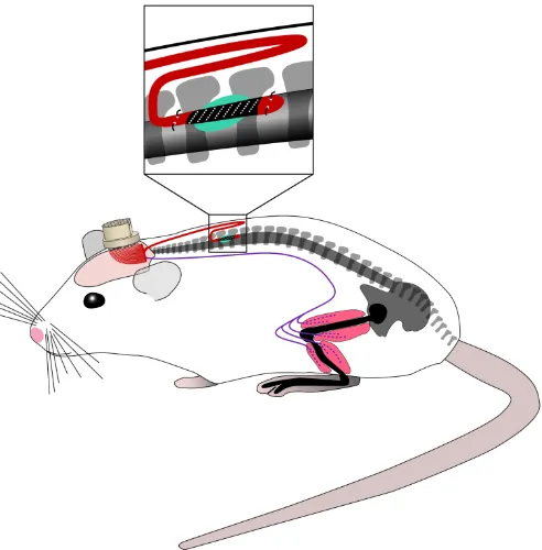
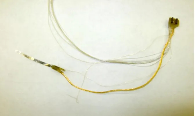
the layout of the array and cable on the wafer is in a U-shape to obtain the necessary length. Figure 2.1 illustrates how the device is implanted into the rat:
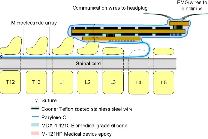
Figure 2.1: Illustration of the fully microfabricated implant and EMG wires positioned into the rat
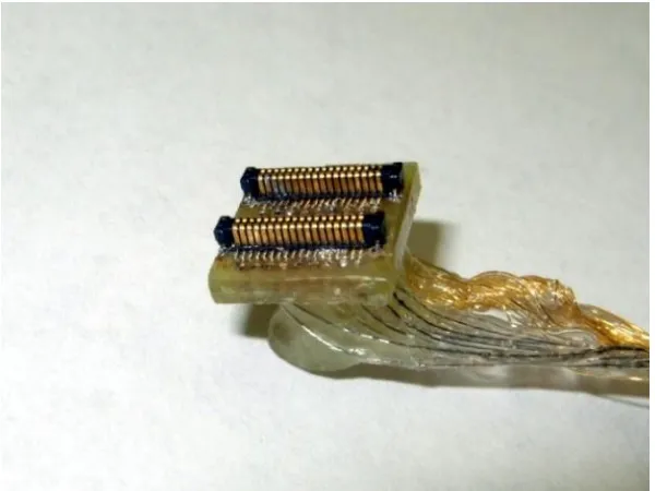
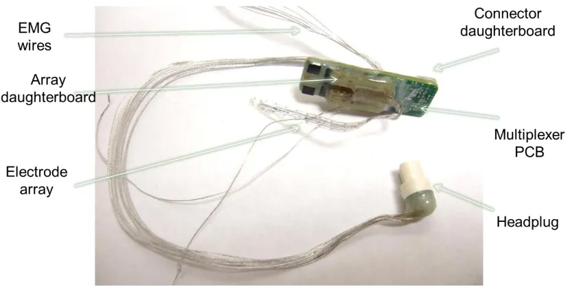
interfaced to the headplug by applying conductive silver epoxy (CircuitWorks CW2400). The complete implant is shown in Figure 2.2.
Figure 2.2: Photograph of the fully microfabricated implant
2.3.1
Fabrication
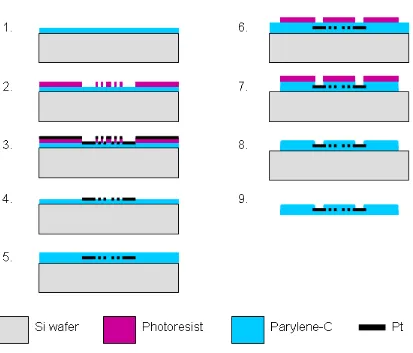
The multielectrode arrays were fabricated as shown in the steps outlined in
Error! Reference source not found.. Approximately 5 m of parylene C was then vapor deposited in a PDS2010 system (Specialty Coating Systems, Indianapolis, IN, USA) on the entire wafer. An LOR3B resist layer (Microchem Corp., Newton, MA, USA) and an AZ1518 photoresist layer (AZ Electronic Materials, Branchburg, NJ, USA) were spun on top of the parylene, exposed in a Kasper 2001 contact aligner (Kasper Instruments, Inc., Sunnyvale, CA, USA) and developed to achieve a liftoff pattern comprising contacts, conductive traces, and electrodes. After hard bake, approximately 2000 Å of platinum was then e-beam evaporated (SE600 RAP, CHA Industries, Fremont, CA, USA) on the wafer. The subsequent photoresist strip generates the desired single-layer metallization pattern. An approximately 5 m thick coating of parylene C is then deposited, followed by a spin coating of photoresist. This photoresist etch mask is exposed over the areas of the electrodes and contact pads and to pattern the overall array geometry, and the entire wafer is then subjected to an RIE in oxygen plasma, removing the parylene insulation over the electrodes and the parylene surrounding the array. The photoresist mask is then removed with solvent. The arrays are finally removed from the silicon by placing the wafer in a deionized water bath and peeling them from their edge. The water will then release the rest of the structure due to the hydrophobicity of the underlying parylene surface.
exposed to any oxygen under elevated temperature, so a 6 hour cooling period is
performed to ensure no section of the oven is over 100°C before venting. The annealing process helps the sandwich structure to form a better bond, as the parylene
polymerization process does not chemically bond with previously deposited parylene exposed to air and the lithographic process.
2.3.2
Surgical Procedure
The surgical procedure involved fixing the array headplug to the skull, implanting the array inside the spinal cord, and transecting the spinal cord to induce lower body paralysis. A second headplug with EMG wires was also implanted, with the EMG wires fed through the body and inserted into leg muscles to monitor activity.
2.3.2.1
Headplug and EMG wires
mm) was removed from the insulation of each wire to expose the conductor and form the electrodes. The wires were secured in the belly of the muscle via a suture on the wire at its entrance into and exit from the muscle belly. The wires were looped at the entrance site to provide stress relief. The proper placement of the EMG wires were verified during the surgery by stimulating the appropriate channels of the headplug.
2.3.2.2
Spinal cord transection and array implantation
A partial laminectomy was performed at the T8-T9 vertebral level and a complete spinal cord transection to include the dura was performed at ~T8 spinal level using microscissors. Two surgeons verified the completeness of the transection by lifting the cut ends of the spinal cord and passing a glass probe through the lesion site. Gel foam was inserted into the gap created by the transection as a coagulant and to separate the cut ends of the spinal cord.
spinal cord, the rostral end of the array was sutured (using 8.0 Ethilon) to the dura to secure it in position.
Figure 2.4: Illustration of the use of a suture to pull the array into the spinal column.
All incision areas were irrigated liberally with warm, sterile saline. All surgical sites were closed in layers, i.e., muscle and connective tissue layers with 5.0 Vicryl (Ethicon, New Brunswick, NJ) and the skin incisions on the back and the limbs with 5.0 Ethilon. All closed incision sites were cleansed thoroughly with warm saline solution. Analgesia was provided by buprenex (0.5–1.0 mg/kg, 3 times/day s.c.). The analgesics were initiated before the completion of the surgery and continued for a minimum of 2 days post-surgery. The rats were allowed to fully recover from anesthesia in an incubator. The spinal rats were housed individually in cages that had ample CareFresh bedding and their bladders were expressed manually 3 times/day for the first 2 weeks after surgery and 2 times per day thereafter. The hindlimbs of the spinal rats were moved passively through a full range of motion once per day to maintain joint mobility.
13 1 2 4
Spinal cord
12 11
10 3 5
2.3.3
Initial Results and Analysis
After the rat had healed for one week, stimulation of the spinal cord through the implant was attempted. Unfortunately, none of the electrodes sites proved to be
responsive at the initial testing or subsequent attempts. Using low frequency (1 Hz or slower) pulses, the rat should show a twitch movement in the legs even in the absence of rhythmic stepping, but none was observed. The implant was then removed to examine the mode of failure.
Figure 2.5: The most damaged section of the explanted array (a) under a microscope (b)
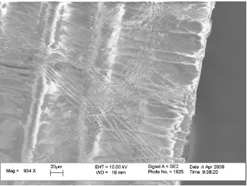
Figure 2.6: Electron micrograph of the explanted array
It was concluded that the design strategy of a fully microfabricated implant, i.e. using a microfabricated cable from the headplug to the spine, would be extremely difficult if not impossible to achieve.
2.4
Wired Microelectrode Array Implant
microfabricated implant passing throught he body has no advantage over wires aside from ease of fabrication, and a major disadvantage of being mechanically fragile. Therefore, a bundle of wires was incorporated into the design to bridge the connection between the headplug and the spine so that the microfabricated portion could be minimized (see Figure 2.7).
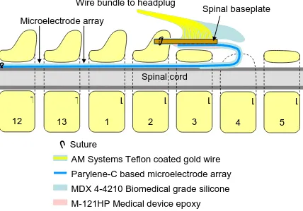
Figure 2.7: Illustration of the wired array implant and EMG wires positioned into the rat. The microfabricated portion is in blue and minimized.
2.4.1
Spinal baseplate
To maximize the success of the design, that there should be minimal movement of the microfabricated portion as it exits the spinal column. To achieve this, we designed a spinal baseplate that could be surgically anchored to the spine through the use of a fork shape that fits around a vertebra’s spinous process, which is a bony protrusion on the dorsal side of each segment. The baseplate had an array of electrical vias so that wires can be soldered to one side and the array could be attached to the other side via conductive epoxy.
There was a choice of two configurations in the layout of the implant after
surgery. The array could either make a U-turn or be kept as straight as possible. Although a straighter path may be a more natural position for the array, closer analysis suggests that when fixing the fork to the spinous process, spinal flexion during rat movement would likely result in more stress on the array, as illustrated in Figure 2.8. The U-turn keeps the fixation point of the fork just above the center of the electrode array,
minimizing total deflection due to spine curvature. It was also determined that it would be somewhat more optimal for the array to enter on the caudal end at vertebra L4 (as opposed to the rostral end at T11), as there is less curvature of the spine in the lumbar region.
Figure 2.8: Top view of two candidate layouts of the spinal baseplate relative to the electrode array during spinal flexion. In red is the portion of the array theorized to undergo greater mechanical stress with the latter layout. The fork fits around the spinous process of a vertebra.
2.4.2
Epoxy and Silicone Encapsulation
A key factor in this implant design is the application of silicone and epoxy. After the electrode array is attached, the spinal baseplate is coated in biomedically compatible
be strengthened. The silicon coating helps prevent the array from bending very sharply and forming creases as we saw in the previous design. It was later found that if the silicon coating is too thick, it would apply pressure to the spinal cord and adversely affect the rat and the experiment, so a layer roughly 100µm thick was applied to as much of the
microfabricated array as possible without covering the electrodes and retain flexibility. A solution of two parts uncured silicone to one part hexane was prepared to obtain a thin enough consistency such that after brushing the silicon on, the desired thickness was obtained.
2.4.3
Headplug design
The 18-pin Omnetics Nano connector used in the first implant’s headplug was found to be cumbersome to assemble form electrical connections to (due to it’s through-hole design), required significant force to mate, and didn’t contain nearly enough connections for the desired number of electrodes and EMG wires. A 27 electrode array (9x3) was designed for this second generation implant to provide all the desired
Figure 2.10: 48-pin custom headplug
2.4.4
Wire bundle design
Figure 2.11: Photograph of the complete wired implant
2.4.5
Surgical Procedure
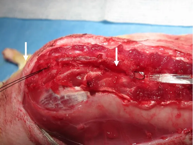
Figure 2.12: Photograph during surgery just before the array is pulled in
The orientation of the spinal baseplate required the array to be inserted in the opposite direction as described in section 2.3.1.1. Figure 2.12 is a photograph of the array just before being drawn into the spinal column with sutures. The suture was inserted through the opening at T11 and passed down to the opening at L4. This suture then was threaded into holes at the most rostral end of the electrode array, back into the opening at L4, and passed down to the first opening at T11.
2.5
Optimization of Electrode Array
While stimulation was achieved with the second generation implant, some of the electrodes would fail after some time. There are two main categories of individual electrode failure: mechanical failure of the trace going from the electrode to the
T
11 L
baseplate, and failure of the electrode itself through delamination. Various design
iterations of the electrode array addressed these issues to improve longevity inside the rat.
2.5.1
Electrode Delamination Prevention
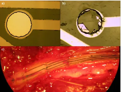
Figure 2.13: Electrode delamination. a) Typical electrode before implantation. b) Some electrodes after explantation showed degradation c) View of an electrode array on the dura of the spinal cord after 4 weeks in vivo, showing delamination.
Electrode delamination has long been a mode of failure for microelectrode arrays in vivo. Initially, we found anywhere from 1 to 7 electrodes out of 27 would undergo significant delamination, as seen in Figure 2.13. Lab tests showed that delamination was not a problem after 3 million pulses (5V amplitude and 1ms duration) were passed through the electrodes while soaking in saline, as seen in figure 2.14. From this, and
a) b)
because the remaining electrodes mostly did not show any delamination at all despite being identical prior to implantation, we hypothesize that it is mechanical stress
combined with chemical processes and electrical stimulation that causes delamination in vivo.
Figure 2.14: Effect of pulse testing on electrode conditionafter a) zero pulses, b) 1 million pules, and c) 3 million pulses
To solve the problem of delamination, we used a two prong approach. First, we deposited a thin 100Å layer of titanium prior to the platinum deposition. Titanium is known to function as an adhesion layer during metal deposition. Secondly, we designed a grid structure over the electrodes, as seen in figure 2.15. The electrodes proved to remain intact after explantation, but show ripples that appear to suggest the onset of
Figure 2.15: Typical electrode before implantation (left) and after explantation (right) when equipped with a grid structure.
2.5.2
Stress Relief Structure
A stress relief structure was designed for one iteration of the electrode array, in which the traces from the electrodes to the pads were of an undulating form.
Unfortunately, this structure did not improve the longevity of the array, as almost all the electrodes failed to stimulate after one week of implantation. Figure 2.16 compares the condition of straight and undulating traces after explantation. While the straight traces do show stress lines, the undulating ones proved to have more severe cracks. It is evident that the curvature of the undulations provide regions of stress concentration. From these areas, cracks in the parylene initiate and then propagate to the traces.
2.5.3
Conductor Redundancy and Final Design
Since the stress relief structures proved to be detrimental to array longevity, the final revision of the array made use of two traces per electrode. To maximize the effectiveness of this strategy, it is desirable for these two traces to be located far from each other so that localized damage to one part of the array would not affect both traces for any electrode. In order to accommodate the number of traces for such a design, the electrode orientation was changed from round to rectangular, offering more room between the electrodes for traces while retaining surface area.
Figure 2.17: Final microfabrication procedure
2.6
Results
The wired implant was able to survive chronic implantation and stimulate the rat, with progressive electrode iterations reducing electrode failure count. Two different types of stimulation experiments were performed on the rat. One involves applying low
frequency (typically 0.3-1 Hz) stimulation pulses of 0.5ms duration to evoke single responses in the leg muscles that show up in the EMG recordings. The other is a stepping experiment, where the rat is placed over a treadmill in a jacket (see figure 2.19 and [48]) and high frequency (typically 40Hz) stimulation invokes a stepping motion as the treadmill is run. Both experiments provide useful data for understanding the neural mechanisms of the spinal cord.
2.6.1
Evoked Responses
Figure 2.20: EMG responses obtained from two different stimulation combinations.The electrode naming convention is shown on the right.
2.6.2
Stepping
Stepping was observed 8-10 days after the rats were spinalized. This is a key improvement over conventional stimulation using wire electrodes, which have generally taken 3 weeks or more for electrical stimulation alone to induce stepping. The reasons for this is unclear, but because stepping in early stages does not occur with every
combination, it is likely that the better site specificity of an electrode array can have greater success in activating the spinal circuits.
Again, it was found that different stimulation combinations can invoke different biological responses. Figure 2.21 shows a stick-diagram representation of stepping patterns from two different stimulation combinations, as captured by a motion capture system.
Figure 2.21: Stepping patterns from two different stimulation combinations
2.6.3
Animal Health Issues
sections. Early designs of the implant had high failure rates, but even when the implant design was refined to be more robust, various health issues were still often seen in the rats. Some of these issues are known to happen on occasion for this type of experiment, such as rats chewing their paralyzed legs, but one issue in particular was related to the wired implant design.
For three of the animals, the wire bundle was found to rub against the underside of the skin. Since movement of the rat can change the distance between the headplug and spine by greater than a factor of 2, the wire bundle needed to be long enough to form a loop under the skin. This loop would sometimes form a kink after days inside a moving rat, and that kink could then rub on the skin enough that it would eventually protrude through. Infection was then inevitable, and these rats had to be terminated.
2.7
Summary
This was the first microelectrode array to be chronically implanted and achieve stepping in spinalized rats. Moreover, stepping was observed much sooner than had been seen before with conventional wire electrodes. The value of having a high number of stimulation sites was illustrated through varying biological responses depending on the sites chosen to stimulation. Depending on the combination of electrodes used, marked differences were seen in the EMG responses, both in terms of amplitude and ratio of monosynaptic and polysynaptic waveforms. Stepping patterns also varied with different stimulation combinations, showing different characteristics in the varying parts of the stepping cycle.
While these observations clearly illustrated the potential of high density electrodes to further study of spinal cord injury and develop effective therapies,
complications arising in some rats during the surgery also suggested that a passive wire bundle is not necessarily the best way to interface between the electrodes and the
3.
Multiplexed Microelectrode Array Implant
3.1
Introduction
In the previous chapter, our work clearly established the value of high density electrode arrays for spinal cord stimulation [49], but it also found significant health risks associated with having a high number of wires passsing down the neck from the headplug to the spinal cord. It is important to address this issue to not only for a higher success rate with this 27-electrode experiment, but also to lay the foundation for a higher electrode count in future studies.
One possible solution to this issue is to use thinner wires, but the wires used in the previous chapter were already known to be thin enough that a risk of wires breaking over the duration of the experiment is a possibility. Taking this possibility to the extreme, a microfabricated cable could shrink the wire bundle substantially, but such an approach had already failed in our initial design, and was judged to have little chance for success with design iterations. The movement of the rat in the region between the spinal cord and headplug is too severe for a relatively fragile microfabricated cable or very fine wires, and past experience suggests that the skull must be used for electrical connections passing through the skin in a chronic experiment.
such a design would require substantial engineering effort, an intermediate solution was identified where a multiplexer circuit would allow many electrode sites to be addressed using far fewer wires. Such a circuit would necessarily be part of an eventual wireless design, because a design without multiplexing would need a separate stimulator circuit for all 27 electrodes, and would not be small enough to implant in a rat.
A major engineering challenge with active electronics in implants is the need to hermetically seal the electronics from bodily fluids while also being biocompatible. Typically, this is done with a biocompatible metallic or glass case, and electrical
connections use ceramics as insulation which are covalently bonded to the case to prevent leakage. Such a case, unfortunately, is not commercially available for the size constraints of the rat and high number of electrical connections for the electrode array, and
developing such a case is well beyond the financial resources of this work.
3.2
Design Requirements
The multiplexer circuit must be able to route the desired stimulation signal, and thus must handle a minimum voltage range of 10V. Up to 20V is desirable, as it was found in previous experiments that such voltages can be useful for obtaining responses if lower voltages do not work. To further reduce the number of wires, it must also route signals from the desired EMG wires to differential preamplifiers.
The circuit is designed to operate in 4 modes to meet the experimental requirements:
B) recording of 4 EMG signals, selected from 8 EMG wire pairs C) recording between almost any pair of electrodes on the spinal cord
D) recording from 4 electrodes in the same column with respect to the fourth (e.g., A1-A9, A3-A9, A5-A9, and A7-A9).
Modes A and B are the primary objectives, while modes C and D are reserved for future investigation. The ability to stimulate EMG wires (in mode A) is needed to check position of EMG implants during surgery, as a stimulation pulse will make the muscle twitch if placed correctly.
The entire circuit must fit in the rat adjacent to the spinal cord much in the same way as the baseboard of the wired implant (described in section 2.4) so that the surgical procedure can remain the same. As such, the maximum dimensions are roughly
40x15x10 mm, as a larger package would present difficulties in placing the implant close to the spine in a manner similar to that described in section 2.4.5, which is a necessity to minimize damage to the electrode array.
This design must use off-the-shelf components only, as custom IC design is costly and time consuming. Finally, it is preferable for the circuit design to take into
3.3
Multiplexed Implant System
Figure 3.1: Multiplexed implant system block diagram
Figure 3.1 illustrates the overall system block diagram, and can be divided into two main sections. In the top half of the figure is the base recording system used with previous stimulation studies [50], and it was kept unchanged to leverage existing hardware and software infrastructure for EMG recording and analysis. This includes LabVIEW software, an ADC, and a multichannel EMG amplifier (AM Systems Model 1700). The bottom half of figure 3.1 shows new external components added needed to control the multiplexer. A second host computer with custom software is used to control the stimulation and multiplexer. This computer is connected to a DIO/ADC box (National Instruments PXI-6123), which is in turn connected to a control box. This box contains the stimulator circuit as well as interfacing between the ADC, the EMG amplifier, and the multiplexed implant. Power is also supplied to the implant by the control box.
headplug containing secondary EMG wires. The latter was not used in all rats, but when used with EMG wires placed in the same muscles as EMG wires placed in the implant, it allowed verification that the multiplexer circuit did not fail to record EMG signals (see section 3.4.1 and figure 3.9 for results).
3.3.1
Layout and Surgery
Figure 3.2: Layout of the multiplexed implant after surgery
The surgery is similar to that of the wired implant (described in section 2.4.5), but there are some slight differences. The array is passed through the spinal column in the same manner, but due to the size of the implant and location of the entry point at the L4 vertebrae, the electronics package is placed over the spinous process that is used to fix the implant. This slightly alters the process by which the implant is fixed to the spine. After passing a suture through holes in the array daughterboard and the hole in the spinous process, it must then go around the top of the implant and tie it down. The final difference is that the EMG wires no longer originate from the headplug, and instead originate from the implant package.
3.3.2
Multiplexed implant
Figure 3.3: Photograph of the multiplexed implant
3.3.3
Multiplexer Circuit
Figure 3.4a: Multiplexer circuit schematic
There are twelve wires connected to the circuit from the headplug. Three of them (not shown in figure 3.4a) are for power, including Vdd (usually 12V, but can be boosted to over 20V), Vcc (5V, but can be as low as 2V), and ground. Three are for digital signals to configure the multiplexer: Clock, Data, and EN. The remaining four signals are A1 to A4, which are the output from the amplifiers.
3.3.3.1
Multiplexer Circuit Operation
Figure 3.4b: Sample configuration of multiplexer to stimulate combination B8-C9
3.3.3.2
PCB Layout
Figure 3.5: Manually routed high-density PCB design for the multiplexer circuit
Figure 3.6: The final PCB for the multiplexed implant
3.3.4
Packaging
amplifiers have an input impedances of 1013Ω, even miniscule amounts of body fluid leaking onto the PCB can cause significant current to leak into the amplifier inputs from other traces.
The procedure found to work best was a multilayer encapsulation of silicone, parylene-C, and biomedical epoxy. The first sealing layer is 20 µm of parylene-C, but some parts need to be sealed from the conformal nature of the coating. The wires, headplug, and pads on the array daughterboard are protected with polyester tape (3M 8402) and a low temperature water-soluble wax at the ends of the tape. Next, the
assembled PCB is dipped in an adhesion promoter solution (100:100:1 ratio of deionized water, isopropyl alcohol, and A-174 adhesion promoter respectively), and then the parylene-C deposition can commence. After removing the tape and wax, a coating of biocompatible silicone (MDX 4-4210) is then applied, using a vacuum chamber to extract as much trapped air as possible before the silicone begins curing. A coating of
biocompatible epoxy (Loctite M-121HP) is then applied to add rigidity to the outside, as silicone has a very low Young’s modulus and can easily be deformed while inside the animal, which can transmit mechanical forces to encapsulation interfaces.
3.3.5
Control Box
The control box has an op-amp circuit (figure 3.7) to generate the stimulation signal. The PWM signal is passed through an RC filter and creates any required analog signal at Vin (0-2.5 V, ~5 µs effective pulse rise time). When Mode is low, the op-amp circuit is transformed to that of a positive gain voltage amplifier, otherwise it becomes a voltage controlled current amplifier. When Mode is high, the drain of transistor Q2 is grounded while the drain of Q3 becomes high impedance, transforming the op-amp circuit to that of a current amplifier. This circuit generates the Stim+ signal to be fed into the implant’s multiplexer circuit along with the control signals and power lines. The Stim+ signal also is fed back to the NI ADC for voltage monitoring, along with the CurrSense+ and CurrSense- signals for current monitoring. The preamp signals A1-A4 from the implant pass through a voltage divider (adjustable) and then are output to the EMG amplifier (AM Systems Model 1700). The Multiplexer circuit routes the
Figure 3.7: Stimulator circuit
3.3.6
Software
of the stimulator, and the bottom right monitors the A1-A4 channels of the multiplexer circuit, which are the outputs of the amplifier chips.
Figure 3.8: Screenshot of software interface during operation
Mode signals for stimulation, and a Sync signal to synchronize EMG recordings with the timing of the stimulation.
3.4
Results
The multiplexed implant proved robust enough to gather substantial in vivo data. The two types of experiments performed on the rats are the same as those described in section 1.2, namely the study of evoked potentials from low frequency stimulation and stepping experiments from high frequency stimulation. Encapsulation was a major issue in early implants, but later implants remained functional for up to 8 weeks.
3.4.1
Evoked Potentials
Evoked potentials were recorded while stimulating with the ground electrode (placed subcutaneously on the back of the rat) acting as the anode and each of the electrodes on the array as the cathode. To confirm that the multiplexed implant was recording EMG signals correctly, some animals had a second implant with wires directly (i.e. without any multiplexer circuit) going into some muscles which also had wires from the multiplexed implant. These animals allowed a comparison of signals from the
Figure 3.9: Comparison of EMG recordings from the multiplexed implant and direct wire recording with external amplification.
Figure 3.10: Middle response from evoked potentials.
By recording the evoked potentials from specific muscles during monopolar stimulation at different intensities, one can assess the activation of the motor pools of the ankle flexor and extensors in the spinal cord, as shown previously [23-26]. One key observation is that stimulation one side of spinal cord (i.e. columns A or C) generate most activity on the same side of the body (i.e. the left or right hindlimb muscles). This
demonstrates the ability to selectively activate different circuitries and to stimulate specific anatomical areas and combinations of motor pools. This potential to selectively activate specific combinations of motor pools and levels of inhibition and excitation translates into the unique capability of electrode arrays to control motor behavior.
3.4.2
Stepping
higher frequencies (80-100 Hz) at some of the rostral electrode pairs resulted in over-activation of the neuronal circuits and produced some non-specific movements in both hindlimbs with no interlimb coordination. In contrast, stimulation between 40-60 Hz at the rostral electrodes resulted in coordinated activation of flexor and extensor muscles in both hindlimbs leading to partial weight-bearing standing and stepping. Thus, distinct motor responses were induced by stimulation of the rostral electrodes at different frequencies.
Bipolar stimulation (40 Hz, pulse width of 0.2 ms, and 3-4 V) using different pairs of electrodes on the spinal cord showed different stepping patters. The results using 6 different bipolar combinations are shown in figure 3.11. These graphs don’t show direct EMG signals, but rather the amplitude of their envelope over the course of the stride [52]. Four combinations with the cathode rostral to the anode resulted in coordinated bilateral stepping showing good interlimb coordination, with two providing good body support (combinations A1-C5 and A1-C7) and two others providing lower body weight support (combinations B4-B6 and B6-B9). Combination C9-B6 produced poor stepping, and with combination A5-A6 the rat was able to generate step-like movements, but with little or no body weight support.
3.5
Summary
4.
Wireless Multielectrode Array Implant
4.1
Introduction
Biocompatibility of implants is a crucial factor in successfully collecting data in chronic experiments. For microelectrode array implants, as the number of electrodes increases, so do the required connections to a wire bundle in order to make connections with external electronics, and the probability of success of the implant due to potential tissue damage and infections caused by the wire bundles. The work in the previous chapter partially addressed this problem by employing a multiplexer to reduce the number of required connections, but it is desirable to eliminate the wired connections entirely and develop a fully wireless implant with multi-channel stimulating/recording. Such a technology is particularly important for scaling up this spinal cord stimulator to different species, such as cats, monkeys, or humans, as biocompatibility is of greater importance. Eliminating wires and the headplug also make the device more easily implantable, so fewer changes are needed to adapt the device to different purposes, locations on the body, and animals.
the ultra-high Q of self-resonant coils. The work presented here will also use inductive coupling to implement wireless power transfer.
4.2
Design Requirements
The basic design requirements for the wireless implant do not change from those introduced in section 3.2, but additional parameters will need to be considered now that the implant will be completely wireless and can’t use external components.
There must be a MCU (microcontroller unit) and wireless transceiver in the device to control the device, receive stimulation parameters, and transmit recorded waveforms. Fortunately, there are a number of combined MCU/transceiver SoCs
commercially available. A sampling rate of 2kHz is the minimum needed to capture most of the relevant biological data, and for four recording channels at 8 bits per sample, that suggests 64 kbps required data transmission. While the MCUs are theoretically capable 500 kbps, preliminary research suggested that real world data transfer was usually under 100 kbps. That suggest the radio will be on most of the time. A quick survey revealed that the radio alone on all suitably sized SoCs needs ~50mW of power (~20-mA at a Vcc of around 2-3V) whether receiving or transmitting.
From this, the specifications of the wireless power subsystem can be determined. The multiplexer circuit consumes minimal power aside from the amplifiers, which
consume a minimum of roughly 4mW each, but to make sure there was enough margin of error, it was assumed that the circuit would need up to 100mW of wireless power
subsystem would also have to deal with considerable movement of the mouse during stimulation, so a target maximum separation goal of 5cm was set.
4.3
Wireless Power Theory
Figure 4.1: Simplified circuit for inductive power transfer
drastically in magnitude with distance as the coupling factor changes. Figure 4.4 shows a plot of efficiency as a function of α. As can be seen, a value of 2 chosen for β is almost optimal at low coupling factors (e.g. for α=0.5, 9.5%) while retaining good coupling efficiency at higher values of α.
Figure 4.4: A plot of wireless power transfer efficiency.
4.4
Wireless Power Implementation
4.4.1
High Q coils
As noted in section 4.3.2, high Q coils are critical to make α as large as possible to improve coupling efficiency. It was found that the straightforward solution of using thicker wire to reduce coil resistance has serious limitations, as shown in figure 4.5.
2 1 2
Q Q k
1 10 100 1000 10000
frequencies due to the proximity effect, and decreases at lower frequencies due to the ω
term in
R L
Q .
4.4.2
Primary Power Amp
The primary amplifier generates a sinusoidal waveform to power the primary coil. A power target of roughly 1W was found to be practical, as it was sufficient to power 100 mW at 5% wireless coupling efficiency, and higher power would heat up the coil too much. The most efficient way to drive a power coil is with a class E amplifier [57], as during operation it uses a transistor (usually a Power MOSFET) that is either fully on or off, burning substantial power only during the transition time. A class E amplifier was designed, but it was found to require extremely precise tuning, as capacitance changes of only 0.1pF could substantially alter the drive waveform. Since amplifier efficiency was not a major concern at this point, a class C amplifer was used instead. The best amplifer chip found at a reasonable price was the LT1206 current feedback amplifier. It is capable of ±12.5V output swing into a 50Ω load (i.e. 250mA), i.e. 1.5W for a sinusoid. A current feedback amplifier was necessary to provide the necessary slew rate of at least 200V/µs required for a 10V sinusoid at 3.2MHz ( fA
dt
dV
2
max
). Figure 4.7 show the final circuit
implant is doing, and the coupling factor can also change, it must communicate to the primary side about whether to increase or decrease power.
Figure 4.8: Ideal wireless power delivery. As α changes, the primary amplifier
amplifier’s voltage (purple, right scale) must adjust to deliver 100mW power (red, left scale). The current (cyan, left scale) will also change as a result of the reflected secondary load changing in impedance. Two distance markings are labeled.
Figure 4.9: Circuit to regulate power absorption by the secondary coil and simulation results. The green trace is the rectified voltage (left scale), and the red trace shows instantaneous power dissipation by the coil (right scale).
requires the rectified voltage to drop down to 5.1V before U1 swings low again. The simulation waveforms in Figure 4.9 verify this behavior. The red waveform is
instantaneous power dissipation of coil L2, and thus has a carrier frequency of 3.2MHz (which is too high a frequency for the time scale of the graph, and why the waveform appears solid red). Its average over a few µs will be half of the peak seen in the figure. When such a simulation was performed without this power absorption regulation
subcircuit, and with identical primary side voltage, the ramping of power absorption seen in Figure 4.9 would continue until it averaged 656mW. With the subcircuit present, it averages at most 160 mW, and only 15mW turning off when not needed.
After the coil’s power absorption is controlled, the implant requires 12V (Vdd) and 2.4V (Vcc) power rails. A voltage multiplier (seen at the top of Figure 4.9 with components D4, D5, and C4) provides Vcc, and it is regulated with a LM3840-12 linear regulator. The rectified voltage of 5.1-5.4V is converted to Vcc using a Texas
4.5
Wireless implant
Figure 4.10: Illustration of the wireless array implant after implantation, and photograph of the complete implant
4.5.1
System Overview
Figure 4.11: Block diagram for the wireless implant system.
Illustrated in figure 4.11 is the block diagram of the wireless implant system. The multiplexer circuit is the same as that illustrated in figure 3.4a, except its signal lines are now interfaced with a MCU as opposed to going to the headplug. The other components of the implant are described in the sections below. The gain control and filter is used for recording, and described in section 4.5.2.1. The stimulator circuit, described in section 4.5.2.2, takes digital signals from the MCU and generates an analog waveform. The wireless power circuit is that shown in figure 4.9.
implant. Each action sends a command to the CC1111F32, which then relays the
command wirelessly to the CC1110F2 in the implant (unless it is a command intended for the primary side only), which in turn will send the appropriate signals to the multiplexer and stimulator circuits. The programs running on both MCUs (written in C and compiled to microcode using IAR Embedded Workbench) coordinates wireless communication between each other, switching between transmit and receive mode as required, and adjusting transmit power depending on how strong the signal was for the other side.
4.5.2
Wireless Microprocessor Transceiver Circuit
At the core of the wireless implant is a CC1110F32 microprocessor transceiver SoC from Texas Instruments. The processor core is based on the 8051 instruction set and runs at 26MHz, and it has a versatile DMA engine to offload data transfer from the MCU. The transceiver is operates in sever ISM radio bands, the highest being 782-928 MHz. This chip was chosen over 2.4 GHz variants to avoid possible interference with
Figure 4.12: Schematic for the microprocessor transceiver circuit
4.5.2.1
Recording
The CC1100FX is equipped with a Delta-Sigma Modulator based analog to digital converter. At the fastest sampling rate of 54 kSamples per second, it has 7-bit accuracy. Up to 8 pins on the processor can be used for analog input, but they are done sequentially. Lower sampling speeds can increase the accuracy up to 12-bit. The implant uses the ADC to record the signals from the analog signal lines A1-A4 coming from the multiplexer circuit, as seen on the left side of Figure 4.12.
A high-pass filter circuit with offset ability appears at each input. Consider the RC network around input A1. Pin P0_1 is an input to the ADC, and has 200kΩ input
capacitor C101, and that offset will depend on P1_0. A low offset also allows the ADC to use a smaller reference voltage, improving the ability to read smaller signals.
4.5.2.2
Stimulation
Figure 4.13: Stimulator subcircuit
The stimulator circuit is similar to the one found in the control box used with the multiplexed implant, and its schematic is shown in Figure 4.13. A PWM signal is controlled by a hardware timer with a period of 31 cycles (corresponding to a frequency of 838 kHz), allowing 32 values for the duty cycle (0 to 31 cycles). The carrier frequency of the PWM signal gets filtered with a notch filter (Cpwm1 and Lpwm1, Q=10), and the remaining components of the PWM signal goes to a low pass filter (C1 and Rpwm3,
tRC=9μs) along with two digital outputs from BIT0 and BIT1, for a total of 128 different
MOSFETs Q1-Q3 determines how the op amp circuit will behave. If Mode is low, Q1 is closed while Q2 is open, and the circuit will behave like a non-inverting amplifier and the stimulator will output constant voltage pulses. If Mode is high, Q1 is open while Q2 is closed, and the circuit will behave like a voltage-to-current amplifier and the stimulator will output constant current pulses. The software is able to control the PWM, BIT0, and BIT1 signals with roughly 2µs timing accuracy.
4.5.3
Power Regulation Daughterboard
Figure 4.13: Daughterboard containing the power delivery control circuit.
4.6
Results
The wireless implant has been almost perfectly functional in a benchtop settin