International Journal of Scientific Research in Computer Science, Engineering and Information Technology © 2019 IJSRCSEIT | Volume 4 | Issue 4 | ISSN : 2456-3307
Transparent Patch Antenna Development for Solar Cell Hybridisation
Anup P. Bhat1, S. J. Dhoble2, K. G. Rewatkar3
1Department of Electronics and Computer Scie, RTM Nagpur University, Nagpur, Maharashtra, India
2Department of Physics, RTM Nagpur University, Nagpur, Maharashtra, India
3Department of Physics, Dr. Ambedkar College, Deekshabhoomi, Nagpur, Maharashtra, India
ABSTRACT
Straightforward fix antennas are microstrip fix antennas that have a specific dimension of optical straightforwardness. Exceptionally straightforward fix antennas are possibly reasonable for incorporation with solar boards of little satellites, which are winding up progressively critical in space investigation. Conventional fix antennas utilized on little satellites rival solar cells for surface territory. Be that as it may, a straightforward fix antenna can be set legitimately over solar cells and resolve the issue of going after restricted surface land. For such coordination, a high optical straightforwardness of the fix antenna is required from the solar cells' perspective. Then again, the antenna ought to have at any rate adequate radiation properties in the meantime. Dynamic coordinated antenna structure strategy is reached out to coincided fix applications trying to improve the general power efficiency of the front end correspondence subsystem.
I. INTRODUCTION
There is a few probability of putting solar cells straightforwardly on the patches. Different mixes like putting solar cells behind reflect cluster antennas have likewise been contemplated. On account of fix antennas, the cells can't be near the patches' transmitting edges because of damaging collaborations. As innovation has been progressing quickly, a thought rose to incorporate the antenna and solar cell into (solid) building square units. These units may then be duplicated as wanted to make a structure whose transmitting gap is additionally utilized as the light – gathering territory. A tale half and half innovation where formless silicon solar cells are either coordinated or physically joined with printed space antennas is exhibited.
This fundamental thought is shown with the assistance of two inventive structures where the solar cells are legitimately developed on a hardened steel ground – plane or stuck onto a standard copper layer imprinted on a dielectric substrate. execution when contrasted and a straightforward juxtaposition of antennas and solar cells.
Straightforward fix antennas, as an uncommon kind of microstrip fix antennas have been considered for over two decades. Their normal structure comprises of a best layer conductive fix, base layer ground, and dielectric substrate in the middle. In this investigation, the best layer conveyor and the dielectric substrate of the fix antenna are should have been optically straightforward.
oxides films as strong strip and work structure where
the conductive oxide, for example, indium tin oxides (ITO), by using coincided sheets on standard and hexagonal conductors sheet for the substrate, models incorporate ordinary glass, spread glass of solar boards, and so on.
An essential use of straightforward fix antennas is their joining with the solar boards for little satellites, where constrained surface zone is an issue for mounting antennas, solar cells, and space instruments. This is of incredible importance for little satellites. Other conceivable applications incorporate reconciliation of antennas with window glass or vehicle windshield or unpleasant best antenna, electrical vehicle following antenna.
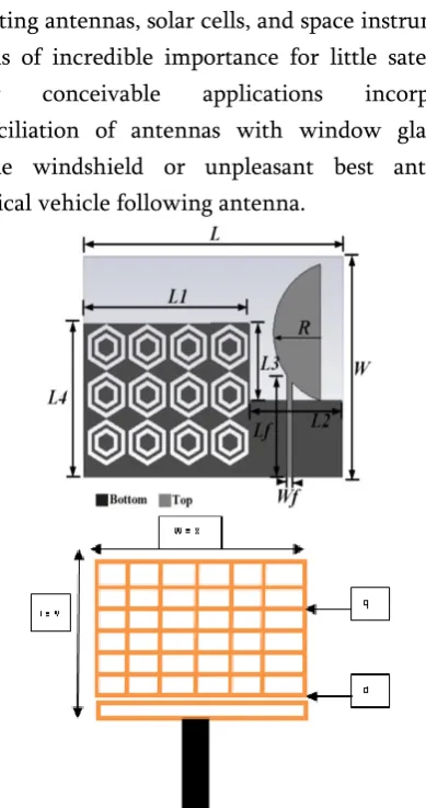
Figure 1 : Antenna design for ITO Glass in Hexagonal and rectangular pattern Mesh Deposition
Table 1: Antenna dimensional parameter
L 45 L3 12
W 35 L4 13
Lf 17 L5 32
Wf 1.2 L6 28
L1 30 a 8
L2 15 g 0.8
These antennas are electrically like customary fix antennas and have similar points of interest. Moreover, they give high optical straightforwardness, which is basic for the solar cells. In this manner, they can be set straightforwardly over the solar board without influencing the solar cells' usefulness. Huge space make expected to agree to the expanding interest for media transmission, interactive media and expanding logical goals. The need to actualize a few complex instruments on one single space make prompts an expansion in the number and size of antennas and solar generators.
For the above issue there is the choice to spare "land" by joining two capacities keeping up execution square with or to expand ability (e.g., to offer correspondence in a non-ostensible circumstance). SONTENNA could even be a mission empowering arrangement.
𝑊 = 𝑐
2𝑓𝑟√( (𝜀𝑟+1)
2 ) (1)
Additionally, the fix length decides the resounding recurrence, and is a basic parameter in structure on account of the inalienable restricted transmission capacity of the fix. The length is found by ascertaining the half-wavelength esteem and afterward subtracting a little length to display the
Straightforward fix antennas can be coordinated with surface-mounted solar boards of little satellites [3] or window glass of structures or autos [4]. These applications require high optical straightforwardness just as great radiation properties of the antenna. Fix antennas produced using straightforward conductive film, for example, silver covered polyester and indium tin oxides (ITO) films, were accounted for [1, 5]. Be that as it may, the straightforwardness of these antennas isn't sufficiently high for viable applications. Reports on coincided fix antennas recommended an unpredictable exchange off between the antenna's properties: the transfer speed and cross-polarization
level can be improved by sacrificing the increase [2];
a low radar cross segment (RCS) can be accomplished if the addition and transmission capacity are undermined [6].
Figure 2: transparent mesh design with solar cell and patch antenna
The polyimide substrate is secured by an aluminum layer (back contact) and by a ZnO layer, which forestalls aluminum dispersion. The layers referenced above additionally structure a mirror for the occurrence solar light so as to expand assimilation and therefore, produce increasingly current. The genuine solar cell is made of three silicon layers: a slight high conductivity phosphor doped n-layer, a natural (un doped) layer with a low imperfection thickness and an extremely meager exceptionally conductive p-layer. Most photons are invested in the natural layer, while the doped layers are in charge of the development of an electric field inside the solar cell itself. The gatherer layer over the cell must be straightforward and conductive and thus it is made of straightforward conductive oxides(TCOs)- either indium tin oxide or zinc oxide. Since TCOs have a somewhat low conductivity contrasted with metals, a finger design is stored on top made of a Cr grip layer secured by thicker Ag layer .Overall the cell thickness is under
Figure 3 : developed solar cell antenna
Mesh structure
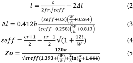
Hypothetically, the geometry of coincided fix antennas can be a self-assertive shape. As referenced before in this segment, nonetheless, the work example ought to be planned dependent on the present ways on the fix that are required for a specific radiation mode. This guarantees unsurprising antenna properties as well as concealment of undesired radiation modes. This paper for the most part centers around rectangular and roundabout fit patches, as delineated in Fig. 3, because of their generally basic work designs. It tends to be seen that a coincided fix antenna
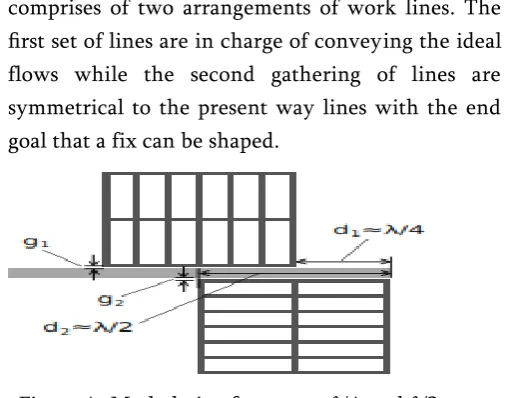
comprises of two arrangements of work lines. The
first set of lines are in charge of conveying the ideal flows while the second gathering of lines are symmetrical to the present way lines with the end goal that a fix can be shaped.
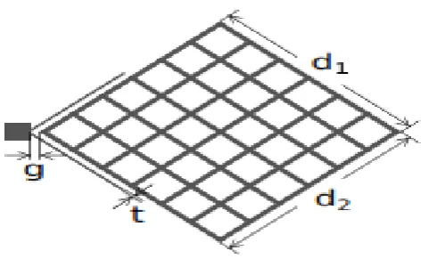
Figure 4: Mesh design for quarter𝜆/4 and 𝜆/2 array antenna design
Table 2: antenna designed with frequency and dielectric basis
Freq Ghz
W
um
L
um
effective dielectric
Ɛreff
Δ L
Lg
um
Wg
Um
1.227
97256392 83180172.61 2.160000035
0.841936 83180180 97256401.2
1.575
75767360 64801315.27 2.160000045
0.841936 64801323 75767369.9
1.72
83917190 80971803.68 1.160000022
1.05366
80971811 83917199.8
2.1
56825520 48600986.28 2.16000006
0.841936 48600994 56825529.8
2.4
49722330 42525862.91 2.160000069
0.841936 42525871 49722339.7
2.6
45897536 39254642.64 2.160000074
0.841936 39254650 45897545.1
3
39777864 34020690.2
2.160000086
0.841936 34020698 39777873.7
The optical transparency of such meshed patches is defined as the percentage of the see-through area of the patch. As an example, the formula to calculate the transparency (T) of a rectangular meshed patch which has a dimension of W (width) by L (length) is given as follows:
𝑡𝑟𝑎𝑛𝑠𝑝𝑎𝑟𝑎𝑐𝑦 = [1 −
𝐴𝑐𝑜𝑛𝑑𝑢𝑐𝑡𝑜𝑟𝐴𝑝𝑎𝑡𝑐ℎ
] ∗ 100 =
[1 −
𝑞(𝑁𝐿+𝑀𝑊)−𝑞2𝑁𝑀𝑊𝐿
] ∗ 100%
(6)
Feed technique
by means of through the solar board is wrong in reasonable structure. In the event that the inset feed line is picked, at that point the geometry of the fit fix must be balanced so as to help a progressively mind boggling current examples because of the abnormality of the fix shape. Because of such focal points, the T-coupling feed structure, was utilized in this investigation.
Figure 5 : mesh design with the T-Coupling axial feed point
As an upgraded sort of closeness line coupling, the T-coupling plan can be utilized to couple a ring resonator or to nourish a round or rectangular antenna [9– 11]. This encouraging technique possibly gives two degrees of opportunity to tuning: the branch thickness and the dividing s as set apart for both rectangular and hexagonal coincided fixes in Fig.
Impact of line width
A lot of test encouraged rectangular coincided fix antennas were structured on ITO , Zn and Glass plate
(μ= 2.6, tanδ = 0.0037, h = 2.132 mm) and analyzed so
as to think about the impact of line width and on the antenna properties. The substrate (roughly 100 mm × 170 mm) was supported with copper. These antennas have similar measurements (45 mm × 35 mm). To accelerate the recreation, the optical straightforwardness was picked to be 70%. It is conceivable to do a similar report with antennas of 90% straightforwardness and achieve a similar end. Be that as it may, the higher the straightforwardness, the smaller the work line width, and increment the proficiency
Impact of Orthogonal Lines
The flows primarily flow on the matrix lines parallel
to the length of the fix (L), while the flows flow on
the lines symmetrical to the length of the fix are negligible [13]. This marvel recommends that lessening the symmetrical lines ought not affect antenna properties in a vast sense and that one can accomplish additional optical straightforwardness by such decrease. The accompanying investigation was set up to break down the effect of the symmetrical lines on the antenna execution. The length and width of the fit fix antenna were stayed to be 37 mm and Table 2.1: Simulated feed point embed remove versus linewidth of rectangular fit patches (45 mm × 37 mm). he work geometry comprises of 25 to 50 lines parallel to the present ways, or length, of the fix and the quantity of lines symmetrical to the fix length changed from 20 to 6 with a fixed line width q of 0.3
mm; subsequently, the optical straightforwardness extended from 70% to 79%.
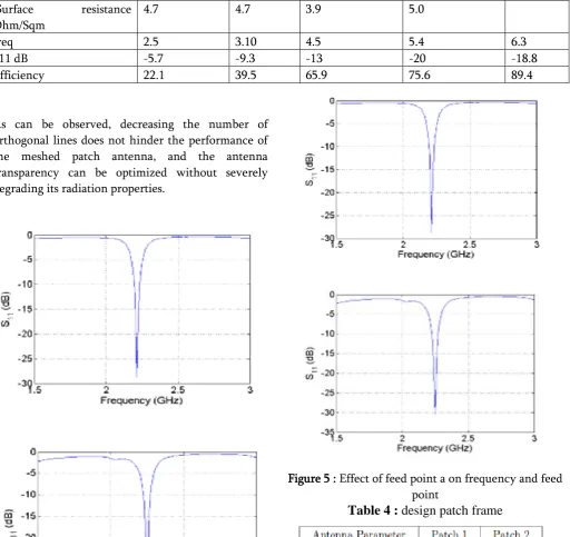
Table 3: transparency basis of the frequency application
Surface resistance Ohm/Sqm
4.7 4.7 3.9 5.0
freq 2.5 3.10 4.5 5.4 6.3
S11 dB -5.7 -9.3 -13 -20 -18.8
Efficiency 22.1 39.5 65.9 75.6 89.4
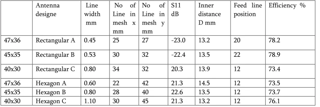
As can be observed, decreasing the number of orthogonal lines does not hinder the performance of the meshed patch antenna, and the antenna transparency can be optimized without severely degrading its radiation properties.
Figure 5 : Effect of feed point a on frequency and feed point
Table 4 :
design patch frame
II. RESULTS AND DISCUSSION
dielectric (for example spread glass) will be the substrate for fit fix antennas, the plan reasoning of the CP fit antennas is the equivalent for straightforward and non-straightforward substrates. Consequently, in the present research center approval, Roger's RO4003C cover (o= 3.55, h = 1.524 mm, tand = 0.0021) was picked to inspect the structure. The two coincided patches are straightforward to lights and the straightforwardness
is defined as the proportion of the seethrough zone
over the whole fix zone.
Figure 6 : current direction with the developed transparent rectangular mesh structure
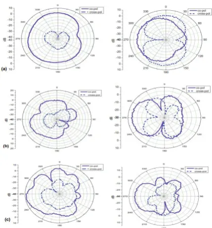
Figure 7 : radiation pattern measure with the antenna
The meshed patches can be placed on solar cells whereas the non-transparent feed line can be placed along the gap between solar cells. The transparency of the meshed antenna can be controlled by the width and the number of the mesh lines. The relation between the transparency and antenna properties has been found [15]. The operational frequency is chosen to be in S band, where the size of the meshed patch is realistic to be placed on top of a commercial triple-junction solar cells used in space applications.
Table 6 : antenna design with the frequency
Freq 2.5 3.10 4.5 5.4 6.3
Patch size
13.5x16 .7
19.3x20 .2
221.0x17 .4
21.5x1 8
7.3x5.5
Line width
0.20 0.16 0.17 0.045 0.13
Loss tange nt
0.00025 6
0.00025 6
0.000256 0.0002 56
0.0002 56
Data transmission Enhancement Mechanism
three antennas utilize a similar feed line and such a
configuration is exceedingly practical to be executed
on a multi-U CubeSat (for example joining a few CubeSats together where each CubeSat has an element of 10 cm × 10 cm × 10 cm) for frequencies higher than S band. The holes between the fit patches and the feed line should be tuned all the while so as to accomplish an impedance coordinating.
Furthermore, it is fundamental for all the three patches to create surface flows in stage, bringing about including bordering fields. Something else, the
radiation would be extraordinarily diminished because of sources wavering in inverse ways. This can be acknowledged when the two nearby fixes are set on different sides of the feed line.
Table 7 : antenna dimension with the solar cell efficiency
Antenna theoretically is framed along the open-finished feed line, diminishing surface flows are incited, by means
of capacitive coupling, flowing in a similar heading
on both the patches. The purpose behind this is the positive voltage on the feed line drives "positive charges" on the upper fix far from the hole side while the negative voltage pulls "positive charges" on the fit antennas is the equivalent for straightforward and non-straightforward substrates. In this way, in the present research center approval,. As a source of perspective antenna, a solitary component square fix with 30 mm side length and 1 mm work line thickness, was intended to reverberate at about 2.48 GHz and manufactured utilizing a circuit board processing machine. The coupling hole and the situation of the fix regarding the tip of the feed line were tuned to get a decent impedance coordinate.
Figure demonstrates the model of the antenna intended for impedance transmission capacity improvement. The transparencies of these patches,
defined as the proportion of the region of the
openings inside the fix to that of the whole fix, are around 70%. This straightforwardness isn't sufficiently high for the genuine applications from the solar cells' point of view, in any case, these parameters were picked for the simplicity of creation utilizing the processing machine and an extremely high straightforwardness can be accomplished by
refining the work lines of the fix with an increasingly
exact assembling office.
IV. REFERENCES
[1]. S. Vaccaro, C. Pereira, J. Mosig, and P. de
Microwaves, Antennas & Propagation, vol. 3, no. 8, pp. 1279–1287, 2009.
[2]. A. P. Bhat, “smart instrumentation technology
for nanostructure antenna and solar cell” Master’s thesis, RTM Nagpur University
Nagpur , India, 2017.
[3]. R. N. Simons and R. Q. Lee, “Feasibility study
of optically transparent microstrip patch
antenna,” IEEE Antennas and Propagation
Society International Symposium, vol. 4, pp. 2100–2103, 1997.
[4]. K. Ito and M. Wu, “See-through microstrip antennas constructed on a transparent
substrate,” 7th IET International Conference on
Antennas and Propagation, pp. 133–136, 1991. [5]. G. Clasen and R. Langley, “Meshed patch
antenna integrated into car
windscreen,”Electronics Letters, vol. 36, no. 9,
pp. 781–782, 2000.
[6]. “Meshed patch antennas,” IEEE Transactions
on Antennas and Propagation, vol. 52, no. 6, pp. 1412–1416, 2004.
[7]. X. He, S. Gong, Y. Ji, and Q. Liu, “Meshed
microstrip patch antennas with low RCS,”
Microwave and Optical Technology Letters, vol. 46, no. 2, pp. 117–120, 2005.
[8]. T. W. Turpin, “Meshed patch antennas
integrated on solar cell - a feasibility study and
optimization,” Master’s thesis, Utah State
University, Logan, UT, 2009.
[9]. N. Outaleb, J. Pinel, M. Drissi, and O. Bonnaud,
“Microwave planar antenna with RF sputtered indium tin oxide films,” Microwave and Optical
Technology Letters, vol. 24, no. 1, pp. 3–7, 2000.
[10]. P. Prajuabwan, S. Porntheeraphat, A. Klamchuen, and J. Nukeaw, “ITO thin films
prepared by gas-timing RF magnetron
sputtering for transparent flexible antenna,”
2nd IEEE International Conference on Nano/Micro Engineered and Molecular
[11]. F. Colombel, X. Castel, M. Himdi, G. Legeay, S.
Vigneron, and E. M. Cruz, “Ultrathin metal layer, ITO film and ITO/Cu/ITO multilayer towards transparent antenna,” IET Science,
Measurement & Technology, vol. 3, no. 3, pp. Propagation Letters, vol. 7, pp. 753–756, 2008. [13]. G. Clasen and R. Langley, “Gridded circular
patch antennas,” Microwave and Optical
Technology Letters, vol. 21, no. 5, pp. 311–313, 1999.
[14]. S.Vaccaro, P.Torres, J.R.Mosig, A.Shah,
“Integratesolar panel antennas,” Electron. Lett.,
vol.36, no.5, pp. 390-391, Mar.2000
[15]. ”Capabilities of printed reflectarray antennas,”
in Proc. IEEE Phased Array Systems and Technology Symp., Boston, MA,Oct.1996, pp. 131-134.
[16]. K. Ito and M. Wu, “See-through microstrip antennas constructed on a transparent
substrate,” 7th IET International Conference on
Antennas and Propagation, pp. 133–136, 1991. [17]. G. Clasen and R. Langley, “Meshed patch
antennas,” IEEE Transactions on Antennas and
Propagation, vol. 52, no. 6, pp. 1412–1416, 2004.
[18]. T. W. Turpin and R. Baktur, “Meshed patch antennas integrated on solar cells,” IEEE
Antennas and Wireless Propagation Letters, vol. 8, pp. 693–696, 2009.
[19]. G. Clasen and R. Langley, “Meshed patch antenna integrated into car windscreen,”
Electronics Letters, vol. 36, no. 9, pp. 781–782, 2000.
[20]. R. N. Simons and R. Q. Lee, “Feasibility study
of optically transparent microstrip patch
Society International Symposium, vol. 4, pp. 2100–2103, 1997.
[21]. X. He, S. Gong, Y. Ji, and Q. Liu, “Meshed
microstrip patch antennas with low RCS,”
Microwave and Optical Technology Letters, vol. 46, no. 2, pp. 117–120, 2005.
[22]. G. Clasen and R. Langley, “Gridded circular patch antennas,” Microwave and Optical
Technology Letters, vol. 21, no. 5, pp. 311–313, 1999.
[23]. D. Pozar, “Five novel feeding techniques for
microstrip antennas,” IEEE Antennas and
Propagation Society International Symposium, vol. 25, pp. 920–923, 1987.
[24]. L. Zhu and K. Wu, “Line-to-ring coupling circuit model and its parametric effects for optimized design of microstrip ring circuits and
antennas,” IEEE MTT-S