Technical Support Services
Accelerated Learning Through the Visual Presentation of Technical Information
Text in pdf documents may appear fuzzy or blocky due to file compression.
To change the appearence in Acrobat
TMReader
TM3.X, go to the menu item:
File / Preferences / General
Deselect “Smooth text and monochrome images” and click OK .
pdf documents
TSS Water Course
Technical Support Services
1050 Kingsmill Pkwy.
Columbus, OH. 43229
ph: 614-885-1658
ph: 800-770-8176
www.techsup.com
Module 8
Electro-Deionization
Technical Support Services
Accelerated Learning Through the Visual Presentation of Technical Information
Contents
8.1 Fundamentals ... 2
8.1.1 EDI Theory of Operation ... 9
8.1.1.1 Ion Exchange ... 10
8.1.1.2 Ion Removal ... 11
8.1.1.3 Regeneration ... 11
8.1.2 EDI Performance... 12
8.1.2.1 EDI Compared to Conventional Mixed-Bed Deionization ... 12
8.2 Process and Operations Overview ... 15
8.2.1 Process Flow ... 16
8.3 Equipment Design and Options ... 23
8.3.1 E-Cell Stack™ ... 24
8.3.2 Control Panel ... 25
8.3.2.1 PLC ... 25
8.3.2.2 Operator Interface ... 26
8.3.3 Brine Injection System (Optional) ... 27
8.3.4 Diverter Valves (Optional) ... 28
8.3.5 Concentrate Pump ... 28
8.3.6 Piping... 29
8.3.7 Valves ... 29
8.3.8 Electrical Power Rectifier ... 30
8.3.9 Instrumentation ... 31
8.4 Applications and Design... 32
8.4.1 E-Cell™ Process Design ... 33
8.4.2 Feed Water Analysis and E-Cell™ Feed Water Specification ... 33
8.4.2.1 Anion and Cation Loading ... 34
8.4.2.2 Calculation of Maximum Allowable Recovery ... 34
8.4.3 Hydraulic sizing ... 35
8.4.4 Brine Injection For Concentrate Loop Management ... 35
8.4.5 Current Determination and Rectifier Sizing ... 36
8.4.6 Concentrate Pump Sizing ... 38
Module 8
Water Course
Electro-Deionization
Technical Support Services
Accelerated Learning Through the Visual Presentation of Technical Information
Table of Contents
8-2 8.1 Fundamentals
Electro-Deionization, or EDI, is a process that evolved from conventional ion
exchange technology. EDI provides continuous demineralization at recovery rates of 90% or more. In EDI, just as in conventional ion exchange, cations and anions in the feed water are exchanged for hydrogen and hydroxyl ions in the ion exchange resins, producing demineralized water. The key operational difference is that with EDI, the ion exchange resin is regenerated continuously, while with conventional ion exchange, chemical regeneration is performed intermittently.
Continuous regeneration in EDI is achieved electrochemically, by means of ion conducting membranes and an imposed electric current. The hydrogen and hydroxyl ions necessary for regeneration are formed in-situ, without addition of chemical reagents, by means of the familiar water dissociation reaction, sometimes called water splitting. Figure 8.1-1 is an illustration representing a water molecule splitting into hydrogen and hydroxyl ions.
Figure 8.1-1: Water Molecule Splitting
H
2
O
OH
Technical Support Services
Accelerated Learning Through the Visual Presentation of Technical Information
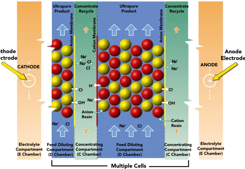
To understand how Electro-Deionization (EDI) removes ions from water, we need to understand the components of an EDI stack and the function of each. An EDI stack consists of multiple beds of ion-exchange material sandwiched with membrane walls and open channels between two electrodes.
The two electrodes are located at opposite ends of the stack, as seen in Figure 8.1-2.
These electrodes supply an electric current to the water flowing inside the cells. One of these electrodes is the cathode. It is negatively charged and is a source of electrons. The cathode attracts cations (positively charged ions).
The second electrode is the anode. This electrode is positively charged and attracts anions (negatively charged ions). This attraction occurs because opposite charges attract and like charges repel. Therefore, a negatively charged cathode attracts positively charged ions, and a positively charged anode attracts negatively charged ions.
Cathode
Electrode
Anode
Electrode
Multiple Cells
Ultrapure Product Concentrate Recycle Ultrapure Product Concentrate Recycle CATHODE ANODE Anion Membrane Cation Membrane Anion Membrane Na+ Cl -Cl -Na+ H+ OH -Anion Resin Na+ Cl -Electrolyte Compartment (E Chamber) Feed Diluting Compartment (D Chamber) Concentrating Compartment (C Chamber) Feed Diluting Compartment (D Chamber) Concentrating Compartment (C Chamber) Electrolyte Compartment (E Chamber) Na+ Cl -OH -Cation Resin Na+ Cl -Na+ Na+ ClWater Course
Electro-Deionization
Technical Support Services
Accelerated Learning Through the Visual Presentation of Technical Information
Table of Contents
The next items we need to notice are the membranes that separate the chambers.
Figure 8.1-3 below shows an EDI stack with the membranes highlighted. There are two types of membranes: anion membranes and cation membranes. Using the same reasoning used for the electrodes, the anion membranes allow only negatively charged ions (anions) to permeate, and the cation membranes allow only the
positively charged ions (cations) to permeate. Water does not permeate these membranes. 8-2 Ultrapure Product Concentrate Recycle Ultrapure Product Concentrate Recycle CATHODE ANODE Anion Membrane Cation Membrane Anion Membrane Na+ Cl -Cl -Na+ H+ OH -Anion Resin Na+ Cl -Electrolyte Compartment (E Chamber) Feed Diluting Compartment (D Chamber) Concentrating Compartment (C Chamber) Feed Diluting Compartment (D Chamber) Concentrating Compartment (C Chamber) Electrolyte Compartment (E Chamber) Cl -OH -Cation Resin Na+ Cl -Na+ Na+ Cl -Na+ Anion Membranes Cation Membrane Cation MembraneCation Membrane Cation Membrane Cation Membrane
Multiple Cells Multiple CellsMultiple Cells Multiple CellsMultiple Cells
Technical Support Services
Accelerated Learning Through the Visual Presentation of Technical Information
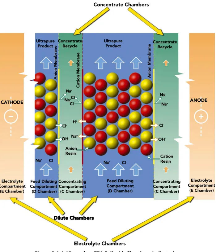
The membranes are situated so that they become the walls that separate chambers. There are three types of chambers; the Dilute or “D” chambers, the Concentrate or “C” chambers, and the Electrolyte or “E” chambers. Figure 8.1-4 shows an EDI stack with the three different types of chambers indicated.
Ultrapure Product
Concentrate Recycle
Ultrapure
Product ConcentrateRecycle
CATHODE ANODE Anion Membrane Cation Membrane Anion Membrane Na+ Cl -Cl -Na+ H+ OH -Anion Resin Na+ Cl -Electrolyte Compartment (E Chamber) Feed Diluting Compartment (D Chamber) Concentrating Compartment (C Chamber) Feed Diluting Compartment (D Chamber) Concentrating Compartment (C Chamber) Electrolyte Compartment (E Chamber) Na+ Cl -OH -Cation Resin Na+ Cl -Na+ Na+ Cl -Concentrate Chambers Electrolyte Chambers Dilute Chambers
Dilute ChambersDilute Chambers Dilute ChambersDilute Chambers
Water Course
Electro-Deionization
Technical Support Services
Accelerated Learning Through the Visual Presentation of Technical Information
Table of Contents
Water to be treated is fed into the Dilute or “D” chamber. This chamber contains a resin bed that consists of cation and anion beads compressed between an anion membrane and a cation membrane. These resin beads allow the ions to adsorb into the respective beads and travel through the beads toward the membranes.
Once contaminant ions pass through the membranes, they are in the Concentrate or “C” chamber. Ions are swept away by a recirculating flow
(the concentrate loop) which has a bleed to prevent an excessive buildup of ions, and a corresponding makeup flow to introduce more fresh water. Figure 8.1-5, below, shows a graphic of an EDI stack with the concentrate loop highlighted.
8-2 Concentrate Loop Concentrate Loop Concentrate Loop