TIG-SL-USB
SignaLink™ USB
Cable List - Rev 14
Last Update - 12March 2009
Tigertronics SignaLink™ USB Digital Interface - Cable
Interface Listing
SignaLink Jumper Settings & Wiring Information For Base & Mobile Radios
References to other non-USB models have been removed from the original Tigertronics document.
Warning: Tigertronics has not verified the accuracy of all of the radio wiring information that is provided here. This information is provided for reference only and is NOT intended to replace the jumper installation procedure in the
“Connecting The Radio” section of the SignaLink Installation Manual. It is essential that you double-check this information against your radio's manual before doing the actual installation. While it is fairly simple to install the SignaLink, it is possible to DAMAGE YOUR RADIO or the SignaLink by incorrectly installing it!
IMPORTANT NOTES
•
SignaLink USB Users - The SignaLink USB is always powered by the computer's USB jack. When installing the jumpers for the SignaLink USB, please disregard the PWR jumper. All other jumper settings are the same. If you mistakenly install the PWR jumper, everything is OK as this pin is NOT connected inside the unit.•
Select The Correct Diagram - When viewing the jumper settings below, BE CERTAIN THAT YOU ARE LOOKING AT THE CORRECT DIAGRAM for the radio connector that you will be using. For any given radio, there are likely to be different jumper settings for the Mic, Data and Accessory Port connectors.•
RJ-45 Mic Connectors - There is a lack of standardization in the way that radio manufacturers number their RJ-45 mic connectors. We have numbered our connector according to the dominant industry standard as shown below. Icom and Radio Shack also follow this standard, but Kenwood, Yaesu and some others do not. You need to be very careful to determine how your mic connector is numbered to avoid reversing connections!
SignaLink™, Industry Standard Kenwood, Yaesu, Some Others
•
PTT - You should verify in your radio manual that the radio PTT requirements do not exceed the specifications of the SignaLink keying circuit (please refer to the SignaLink manual) and that the PTT line is “Grounded” to make the radio transmit. If your radio exceeds the specifications listed or requires some other keying arrangement, then please contact our Technical Support Staff for suggestions.•
POWER - The SignaLink USB is always powered by the computer's USB jack. When installing the jumpers for the SignaLink USB, please disregard the PWR jumper. All other jumper settings are the same. If you mistakenly install the PWR jumper, everything is OK as this pin is NOT connected inside the unit.
Note that the SignaLink USB is always powered by the computer, so you can disregard the PWR jumper when installing this unit.
•
RECEIVE AUDIO / SPEAKER AUDIO - Receive Audio is available on the Mic, Data, and Accessory Port connectors of most radios. If Receive Audio is not shown in the jumper settings for your radio, then consult your radio manual to see if it is available. If it is not, then you will need to connect a mono cable between your radio's External Speaker or headphone jack, and the "Speaker" jack on the back of the SignaLink. See the SignaLink Installation Manual for details.SELECT A MANUFACTURER
ADI
8-Pin Round Mic Connector use TIG-SL-CAB8R
JP-1 Pin-out
Pin 1 - Mic Input Pin 2 - PTT Pin 3 - N/C Pin 4 - N/C Pin 5 - N/C Pin 6 - Speaker** Pin 7 - N/C Pin 8 - GND Radio Models AR-146/147/446 Notes
**Speaker audio is available on some models. Check your radio manual for availability of these signals and add the appropriate jumpers.
ALINCO
8-Pin Round Mic Connector use TIG-SL-CAB8R
JP-1 Pin-out
Pin 1 – Mic Input Pin 2 – PTT Pin 3 – N/C Pin 4 – N/C Pin 5 – N/C Pin 6 – N/C** Pin 7 – GND Pin 8 – GND Radio Models ALD-24T ALR-22T/22HT/72T DR-110T/112T DR-130T/135E/135T DR-150/235T DR-430T/435E/435T DR-510T/570T DR-590T/592T/599T DR-600T/610E/610T DR-620E/620T DX-70T/70TH/70EH DX-77 Notes
**Speaker audio is available on some models. Check your radio manual for availability of these signals and add the appropriate jumpers.
RJ-45 Mic Connector TIG-SL-CABRJ4
JP-1 Pin-out Pin 1 – N/C Pin 2 – N/C Pin 3 – N/C Pin 4 – PTT Pin 5 – Mic GND Pin 6 – Mic Input Pin 7 – GND Pin 8 – N/C
Radio Models
DR-605E/605T
Notes
Speaker audio is available on some models. Check your radio manual for availability of these signals and add the appropriate jumpers.
AZDEN
8-Pin Round Mic Connector TIG-SL-CAB8R
JP-1 Pin-out
Pin 1 – Mic Input Pin 2 – GND Pin 3 – N/C Pin 4 – N/C Pin 5 – N/C Pin 6 – N/C Pin 7 – PTT Pin 8 – N/C Radio Models PCS 5000/6000 PCS 7000 Notes
Speaker audio is available on some models. Check your radio manual for availability of these signals and add the appropriate jumpers.
DRAKE
4-Pin Round Mic Connector TIG-SL-CAB4R
JP-1 Pin-out
Pin 1 – Mic Input Pin 2 – PTT Pin 3 – N/C Pin 4 – GND Radio Models TR-7/22/33 UV-3 Notes
Elecraft
8-Pin Round Mic Connector TIG-SL-CAB8R
JP-1 Pin-out Pin 1 - Mic Pin 2 - PTT Pin 3 - NC Pin 4 - NC Pin 5 - NC Pin 6 - +5VDC Pin 7 - GND Pin 8 - GND Radio Models K2 K3 Notes
The Mic jack on the K2 can be wired a number of different ways, so before installing the jumper wires, you MUST verify that the pin-out of your K2 matches that shown here.
ICOM
4-Pin Round Mic Connector TIG-SL-CAB4R
JP-1 Pin-out
Pin 1 – Mic Input Pin 2 – PTT Pin 3 – N/C Pin 4 – GND Radio Models IC-22/202/215 IC-245/280/402/502 IC-551 IC-701 Notes
8-Pin Round MIC Connector TIG-SL-CAB8R
IMPORTANT: This diagram is for the MIC JACK only. If the SignaLink is attached to your radio's 8-pin Accessory Port, then please see the diagram below under "8-pin DIN Accessory Port Connector".
JP-1 Pin-out
Pin 1 – Mic Input Pin 2 – N/C** Pin 3 – N/C Pin 4 – N/C Pin 5 – PTT Pin 6 – GND Pin 7 – GND Pin 8 – Speaker** Radio Models IC-1201/1271/1275 IC-22U/25/27/28 IC-228/229/251AE IC-255/260/271/290 IC-2400/2500 IC-37A/38A/375 IC-3200/3210/3220 IC-45/47/48 IC-471/475/490 IC-505/551/560/575 IC-707/718/720/725/726 IC-728/729/730/735 IC-736/737/738/740/745 IC-746/746PRO IC-756/756PRO IC-756PROII/PROIII IC-7400/7700/7800 IC-751/761/765/775/781 IC-820H/901/910 Notes
**Speaker audio (usually Pin #8) is available on some models. Check your radio manual for availability of these signals and add the appropriate jumpers.
** Check Other Listings for these radios - you may be able to use the DIN, PACKET , ACCESSORY, or DATA jack **
RJ-45 Mic Connector TIG-SL-CABRJ4
JP-1 Pin-out Pin 1 – +8V** Pin 2 – N/C Pin 3 – Speaker** Pin 4 – PTT Pin 5 – GND (mic) Pin 6 – Mic Input Pin 7 – GND Pin 8 – N/C Radio Models IC-207H**/208H** IC-281A/281E/281H IC-703/706/706MKII IC-2000 IC-2100H**/2200H** IC-2700**/2720H** IC-2800** IC-7000** IC-V8000** ID-800H** Notes
**Speaker audio is available on some models. Check your radio manual for availability of these signals and add the appropriate jumpers.
**Speaker Audio is NOT available on the Mic jack of this radio.
** Check Other Listings for these radios - you may be able to use the DIN, PACKET , ACCESSORY, or DATA jack **
6-pin Mini DIN Data Port Connector TIG-SL-CAB6PM
JP-1 Pin-out Pin 1 – Data In Pin 2 – Ground Pin 3 – PTT Pin 4 – 9600 Out Pin 5 – 1200 Out Pin 6 – Squelch Radio Models IC-207H/208H IC-2720H IC-2800** IC-2820 IC-703/706MKIIG IC-746PRO IC-7000 / 7400 IC-910H Notes
For special signals requiring un-filtered "discriminator" audio, you will need to move the "SPKR" jumper to pin #4 (9600 baud output). Note that some newer radios do NOT provide this output, so this may not apply to your radio.
**Mic audio is NOT muted on this radio.
8-pin DIN Accessory Port Connector TIG-SL-CAB8PD
IMPORTANT: This diagram is for the ACCY PORT only. If the SignaLink is attached to your radio's 8-pin Round Mic Jack, then please see the diagram above under "8-Pin Round MIC Connector".
JP-1 Pin-out Pin 1 - RTTY or N/C Pin 2 - Ground Pin 3 - Send Pin 4 - Mod In Pin 5 - AF Out Pin 6 - Squelch Pin 7 - +13.8V Pin 8 - ALC Radio Models IC-275A IC-707 IC-725/728/729 IC-735/736/737 IC-7400 IC-746** IC-746PRO** IC-756 / 756PRO IC-756PROII / III IC-761/765 IC-775/775DSP IC-781 IC-7700/7800 IC-820H/821H IC-910H IC-M700PRO IC-M710 IC-M802 Notes
IC-756PRO users should use digital mode "D-USB" or "D-LSB".
**Some customers have reported that the IC-746 (early model only) does NOT mute the Mic when keyed from the Accy Port. If this is the case with your radio, then you will need to turn the radio's Mic Gain down and/or unplug the microphone.
**Due to the design of the IC-746PRO, this jack does NOT support VHF operation. If you want to operate both HF and VHF, then you'll need to use the 6-pin mini-DIN Data Port instead.
**IC-746PRO users should use "USB/LSB Data" mode (not regular USB/LSB).
IC-820H users need to set the Modulation Input Sensitivity switch to "Low", and the Baud Rate Selection switch to "AMOD".
13-pin DIN Accessory Port Connector TIG-SL-CAB13I
JP-1 Pin-out
Tigertronics manufactures a special cable for ICOM 13-pin Accessory Ports. If you would like to build your own 13-pin cable (not recommended!), please contact our Technical Support Staff for pin-out and wiring information.
Radio Models IC-703 IC-706/706MKII IC-706MKIIG IC-718 IC-7000** Notes
For VHF operation on the 706 and IC-706MKII you will need to move the PTT jumper to Pin #4.
For VHF/UHF operation on the IC-706MKIIG and IC-7000, you should turn the following menu item to OFF:
Item #30 for IC-706MKIIG Item #20 for IC-7000
This will force the radio to use the same PTT pin for all bands so will not need to change the SignaLink's jumper settings.
**This radio does NOT mute the Mic jack when using the Accy Port, so you will need to turn the Mic Gain down, or use the 6-pin Mini Din Data Port instead.
24-pin DIN Accessory Port Connector - Tigertronics does not manufacture a cable for the ICOM 24-pin Accessory Port connector, but you can easily build one using our un-terminated radio cable (p/n SLCABNC). To build your cable, simply wire it straight-through for pin numbers 1-8 (Pin #1 to Pin #1, Pin #2 to Pin #2, etc.). Note that your cable MUST wired straight-straight-through or the jumper settings shown below will NOT work, and you might DAMAGE YOUR RADIO OR THE SIGNALINK!
JP-1 Pin-out
Pin 1 - NC Pin 2 - +13.8V Pin 3 - PTT Pin 4 - AF Out Pin 5 - Mic Input Pin 6 - NC Pin 7 - NC Pin 8 - GND Pins 9-24 NC Radio Models IC-251AE IC-730/751 Notes
Pins marked as "NC" are not used by the SignaLink, but might be connected internally inside the radio.
Japan Radio Company
8-Pin Round Mic Connector TIG-SL-CAB8RJP-1 Pin-out Pin 1 - N/C Pin 2 - N/C Pin 3 - N/C Pin 4 - +9V Pin 5 - GND Pin 6 - PTT Pin 7 - Mic GND Pin 8 - Mic Input
Radio Models
JST-145/245
Notes
KENWOOD
4-Pin Round Mic Connector TIG-SL-CAB4R
JP-1 Pin-out
Pin 1 – Mic Input Pin 2 – PTT Pin 3 – GND Pin 4 – Mic GND Radio Models TR-7200A TR-7400A TR-7500 TS-120S/130S/180S TS-511S/520/530 TS-600/700/820/830 Notes.
8-Pin Round Mic Connector TIG-SL-CAB8R
JP-1 Pin-out
Pin 1 – Mic Input Pin 2 – PTT Pin 3 – N/C Pin 4 – N/C Pin 5 – 8 VDC** Pin 6 – Speaker** Pin 7 – Mic GND Pin 8 – GND Radio Models TM-201/211/221/231 TM-241/2530/2550 TM-2570 TM-321/331/3530/401 TM-421/431/441/521 TM-531/541/621/631 TM-701/721/731 TR-50/751/851 TS-50/60/140/430/440 TS-450/570/660/670 TS-680/690/701/711 TS-780/790/811/850 TS-870/930/940/950 TS-2000 TW-4000/4100 Notes
**Speaker audio is available on some models. Check your radio manual for availability of these signals and add the appropriate jumpers.
** Check Other Listings for these radios - you may be able to use the DIN, PACKET , ACCESSORY, or DATA jack **
RJ-45 Mic Connector TIG-SL-CABRJ4
JP-1 Pin-out Pin 1 – NC Pin 2 – Speaker** Pin 3 – Mic Pin 4 – GND Pin 5 – PTT Pin 6 – GND Pin 7 – +8V** Pin 8 – NC Radio Models TM-251/255/261/271 TM-451/455/461 TM-641/642 TM-732/733/741/742 TM-941/942 TM-D700A TM-G707 TM-V7A/V71A TS-480HX/SAT Notes
**Speaker audio is available on some models. Check your radio manual for availability of these features and add the appropriate jumpers.
** Check Other Listings for these radios - you may be able to use the DIN, PACKET , ACCESSORY, or DATA jack **
6-pin Mini DIN Data Port Connector TIG-SL-CAB6PM
JP-1 Pin-out Pin 1 – Data In Pin 2 – Ground Pin 3 – PTT Pin 4 – 9600 Out Pin 5 – 1200 Out Pin 6 – Squelch Radio Models TM-251 TM-271**/271A** TM-451 TM-D700/D700A TM-D710/710A/E TM-G707 TM-V7/V7A/V71A TS-480HX/SAT Notes
For special signals requiring un-filtered "discriminator" audio, you will need to move the "SPKR" jumper to pin #4 (9600 baud output). Note that some newer radios do NOT provide this output, so this may not apply to your radio.
**Only European models of the TM-271 and TM-271A have the 6-pin mini-DIN Data Port. All other models will need to use the RJ-45 Mic cable.
13-pin DIN Accessory Port Connector TIG-SL-CAB13K
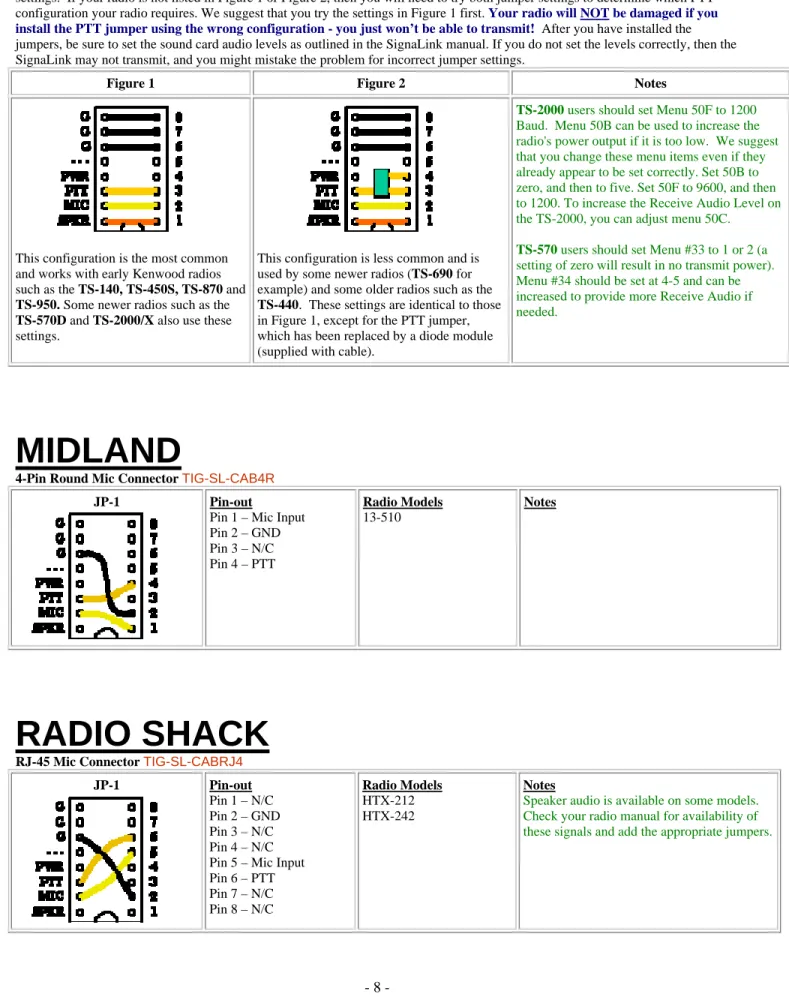
Our 13-pin cable works with ALL Kenwood radio's that have a 13-pin Accessory Port, however there are two possible jumper settings. If your radio is not listed in Figure 1 or Figure 2, then you will need to try both jumper settings to determine which PTT configuration your radio requires. We suggest that you try the settings in Figure 1 first. Your radio will NOT be damaged if you install the PTT jumper using the wrong configuration - you just won’t be able to transmit! After you have installed the jumpers, be sure to set the sound card audio levels as outlined in the SignaLink manual. If you do not set the levels correctly, then the SignaLink may not transmit, and you might mistake the problem for incorrect jumper settings.
Figure 1 Figure 2 Notes
This configuration is the most common and works with early Kenwood radios such as the TS-140, TS-450S, TS-870 and
TS-950. Some newer radios such as the
TS-570D and TS-2000/X also use these settings.
This configuration is less common and is used by some newer radios (TS-690 for example) and some older radios such as the
TS-440. These settings are identical to those in Figure 1, except for the PTT jumper, which has been replaced by a diode module (supplied with cable).
TS-2000 users should set Menu 50F to 1200
Baud. Menu 50B can be used to increase the radio's power output if it is too low. We suggest that you change these menu items even if they already appear to be set correctly. Set 50B to zero, and then to five. Set 50F to 9600, and then to 1200.To increase the Receive Audio Level on the TS-2000, you can adjust menu 50C.
TS-570 users should set Menu #33 to 1 or 2 (a
setting of zero will result in no transmit power). Menu #34 should be set at 4-5 and can be increased to provide more Receive Audio if needed.
MIDLAND
4-Pin Round Mic Connector TIG-SL-CAB4R
JP-1 Pin-out
Pin 1 – Mic Input Pin 2 – GND Pin 3 – N/C Pin 4 – PTT Radio Models 13-510 Notes
RADIO SHACK
RJ-45 Mic Connector TIG-SL-CABRJ4JP-1 Pin-out
Pin 1 – N/C Pin 2 – GND Pin 3 – N/C Pin 4 – N/C Pin 5 – Mic Input Pin 6 – PTT Pin 7 – N/C Pin 8 – N/C Radio Models HTX-212 HTX-242 Notes
Speaker audio is available on some models. Check your radio manual for availability of these signals and add the appropriate jumpers.
SGC
8-Pin Round Mic Connector TIG-SL-CAB8R
JP-1 Pin-out Pin 1 – Mic Pin 2 – PTT Pin 3 – NC Pin 4 – NC Pin 5 – NC Pin 6 – RX Audio Pin 7 – Mic GND Pin 8 – GNC Radio Models SGC-2020 Notes
TEN-TEC
4-Pin Round Mic Connector TIG-SL-CAB4R
JP-1 Pin-out
Pin 1 – Mic Input Pin 2 – GND Pin 3 – PTT Pin 4 – N/C Radio Models Pegasus Notes
These jumper settings work with most Ten-Tec Mic jacks (not just the Pegasus). However you should verify that your radio has the same pin-out before installing them.
** Check Other Listings for these radios - you may be able to use the DIN, PACKET , ACCESSORY, or DATA jack **
5-Pin DIN Accessory Connector - TIG-SL-CAB5PD
JP-1 Pin-out
Pin 1 - Mic Input Pin 2 - GND Pin 3 - PTT Pin 4 - AF Output Pin 5 - NC Radio Models Argonaut V Jupiter Omni VII Pegasus Notes
The Ten-Tec Jupiter must be in "Line" to use the ACCY jack (set in radio menu).
8-Pin DIN Accessory Connector - Orion & Orion II OnlyTIG-SL-CAB8PD
JP-1 Pin-out
Pin 1 - Aux In Pin 2 - GND Pin 3 - PTT Pin 4 - Line Out** Pin 5 - NC Pin 6 - Line Out** Pin 7 - FSK Pin 8 - NC Radio Models Orion Orion II TEN-TEC Delta II Users: Our 8-pin DIN cable is NOT compatible with the TEN-TEC Delta II. You must connect the SignaLink to this radio's 4-pin Mic jack.
Notes
**On the original Orion, the "Audio" menu determines what audio is available on pins 4 and 6, so the SPKR jumper will need to be set accordingly.
**On the Orion II, Pin #4 is ALWAYS the audio output.
YAESU
4-Pin Round Mic Connector TIG-SL-CAB4R
JP-1 Pin-out
Pin 1 – GND Pin 2 – Mic Input Pin 3 – PTT Pin 4 – N/C Radio Models Notes
8-Pin Round Mic Connector TIG-SL-CAB8R
JP-1 Pin-out Pin 1 – N/C Pin 2 – N/C Pin 3 – N/C Pin 4 – N/C Pin 5 – N/C Pin 6 – PTT Pin 7 – GND Pin 8 – Mic Input
Radio Models FT-747/757 FT-757GX/767GX FT-840 FT-847** FT-890** FT-920** FT-950** FT-990** FT-1000** FT-1000D** FT-1000MP** FT-2200 FT-5100 Notes
**On the 890, 990, and the FT-1000 and FT-1000D, you should also jumper Pin #2 and Pin #5 to Ground.
**On the 847, 920, 950 and FT-1000MP, you should also jumper Pin #5 to Ground.
Speaker audio is available on some models. Check your radio manual for availability of these signals and add the appropriate jumpers.
** Check Other Listings for these radios - you may be able to use the DIN, PACKET , ACCESSORY, or DATA jack **
RJ-11 Mic Connector TIG-SL-CABRJ1
JP-1 Pin-out
Pin 1 – N/C Pin 2 – N/C Pin 3 – +9V Pin 4 – GND Pin 5 – Mic Input Pin 6 – SW1 Pin 7 – N/C Pin 8 – N/C Radio Models FT-100** FT-1500M FT-1802 FT-2800M FT-7800R Notes
**With the FT-100, the PTT jumper MUST be replaced with a standard 1/4 watt 27k resistor.
Other Yaesu models with an RJ-11 Mic jack might also use these same settings (check your radio manual).
RJ-45 Mic Connector TIG-SL-CABRJ4
JP-1 Pin-out
Pin 1 – N/C Pin 2 – Speaker Pin 3 – PTT Pin 4 – Mic Input Pin 5 – GND Pin 6 – N/C Pin 7 – N/C Pin 8 – N/C Radio Models FT-2400 FT-2500 Notes
Speaker audio is available on some models. Check your radio manual for availability of these signals and add the appropriate jumpers. Pin-out Pin 1 – N/C Pin 2 – N/C Pin 3 – N/C Pin 4 – Mic GND Pin 5 – Mic Pin 6 – PTT Pin 7 – GND Pin 8 – N/C Radio Models FT-450 FT-817 FT-897 FT-900 Notes
Receive Audio is not available on this connector.
** Check Other Listings for these radios - you may be able to use the DIN, PACKET , ACCESSORY, or DATA jack **
5-Pin Din Packet Connector TIG-SL-CAB5PD
JP-1 Pin-out
Pin 1 – Data In Pin 2 – GND Pin 3 – PTT Pin 4 – Data Out Pin 5 – NC Radio Models FT-920** FT-1000D/MP** FT-1000MPMKV** FT-1000MPMKV-Field** FT-2000 FTDX-9000/D/MP Notes
**On the FT-920, the AFSK/FSK switch MUST be set to AFSK, and you must be in "Data" mode (push the front panel "Data" button). The Mic Gain control appears to affect the operation of the Packet jack, so we suggest setting this to 50% and then adjusting as needed.. **The FT-1000MPMKV and FT-1000MKV Field MUST be in "Packet" mode (NOT usb!) for digital operation. For PSK31 or other "USB" digital modes, you'll need to set your radio's "User Mode" (selection 8-6) to "PS31U". This will configure the radio to look at the Packet jack and use the correct side band for PSK31. For more detailed information on this (including settings for other modes), see "Digital Modem Operation" in your radio manual.
**This jack supports only FM and LSB, which is not compatible with the majority of digital modes.
6-pin Mini DIN Data Port Connector TIG-SL-CAB6PM
JP-1 Pin-out Pin 1 – Data In Pin 2 – Ground Pin 3 – PTT Pin 4 – 9600 Out Pin 5 – 1200 Out Pin 6 – Squelch Radio Models FT-100/100D FT-817/817ND FT-450 FT-847** FT-857/897*** FT-950 FT-1500M FT-7100/7800R FT-8100/8800R Notes
For special signals requiring un-filtered "discriminator" audio, you will need to move the "SPKR" jumper to pin #4 (9600 baud output). Note that some newer radios do NOT provide this output, so this may not apply to your radio.
**On the FT-847 the Data Port supports VHF & UHF Packet only.
FT-847 ONLY - 3.5mm Stereo "Data I/O" jack TIG-SL-CABNC
For the FT-847, we recommend that you attach the SignaLink to the "Data I/O" jack. This jack works for all modes and will let you keep your microphone plugged into the radio. We do not stock a cable for this jack however, so you will need to build your own using one of our un-terminated radio cables. The picture below shows how to wire this cable and install the jumper wires.
© DX Engineering 2009 P.O. Box 1491 · Akron, OH 44309-1491
Phone: (800) 777-0703 · Tech Support and International: (330) 572-3200 Fax: (330) 572-3279 · E-mail: [email protected]
© 1996-2009 Tigertronics. All Rights Reserved , BayPac, SignaLink, and TigerTrak are trademarks of Tigertronics All other trademarks are the property of their respective owners