Quantitative Software Management
MEASURES FOR EXCELLENCE
SIZING
AND
CONTROLLING
INCREMENTAL
SOFTWARE DEVELOPMENT
J. Greene QSM Ltd 5 Haarlem Road Brook GreenLondon W14 0JL Tel : 44-171-603-9009 Fax : 44-171-602-6008
Introduction
Traditional software development methods are increasingly being supplemented by a variety of forms of incremental development. In this paper we set out the major forms and discuss the approaches to estimating their size as well as controlling their development progress.
The need to clarify the form of incremental development arises because of the associated risk especially when estimating the time and effort. The simple statement “incremental development” needs to be qualified to identify more precisely the proposed development process. Such definition in turn allows a clearer understanding of the possible ways of estimating and controlling progress.
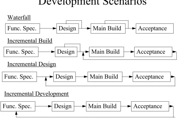
In Figure 1 below are outlined the four major development scenarios based on the four basic phases of specification, design, main software build and
acceptance.
Development Scenarios
Func. Spec.
Design
Main Build
Acceptance
Func. Spec.
Design
Main Build
Acceptance
Func. Spec.
Design
Main Build
Acceptance
Func. Spec.
Design
Main Build
Acceptance
Waterfall
Incremental Build
Incremental Design
Incremental Development
Figure 1 : Software Development Scenarios
The traditional waterfall model of development offers less scope to reduce the time to make delivery of parts of a new system. However it does offer the
advantage of defining what has to be developed as well as enabling a complete design to be made that meets the full requirements. This approach minimises risk with respect to the requirements and the associated design.
In contrast incremental development as shown in Figure 1 is very high risk. This is due to incomplete specifications and, as a consequence, the associated design uncertainty that can result in altering earlier increments. Without
knowing the full requirement it becomes increasingly difficult and dangerous to develop a design that meets later unknown requirements.
Between these two extremes are two other forms : incremental build and incremental design.
Incremental build assumes the overall specification and design are complete. This results in increased confidence that the development will meet user
requirements with an overall design that supports the full system. Hence there is reduced risk of the overall design not working or unknown requirements changes appearing to cause earlier increments to be thrown away.
Incremental design assumes a complete specification but now each increment progresses the design. This increases the risk of significant design revisions if the new design increment reveals shortcomings in the earlier design elements. It is our observation that “incremental “ is often synonymous with “iterative” and “prototyping”. Hence these other forms of development can be treated in a similar way in order to clarify the implications regarding sizing, estimating and control.
Objectives
In this paper we set out the consequences of each of the possible software development scenarios in order to examine their consequences on estimation and control.
Our objectives are to :
• highlight the risk associated with each development scenario • show how the size of the software can be quantified as an input to
development estimation and control
• specifically show how each increment can be sized and the associated uncertainty determined
• demonstrate how to use the increments and their sizes to track and monitor development progress
Size is a key measure as an input to determine the time and effort to develop software. (Ref. 1) Equally tracking progress during development makes use of the size and status of the software at any given point. (Ref. 3)
The metrics used for sizing software can be any of a wide variety of measures such as effective lines of code (ELOC), source statements (SS), logical input statement (LIS), components, objects or function points where business systems are being developed. Logical Input Statements, LIS, clarify what is being
estimated and tracked when none procedural languages (for instance fourth generation languages) are being used.
Again guidelines exist to give consistent ways of quantifying the size of software. (Refs. 2, 4 and 5)
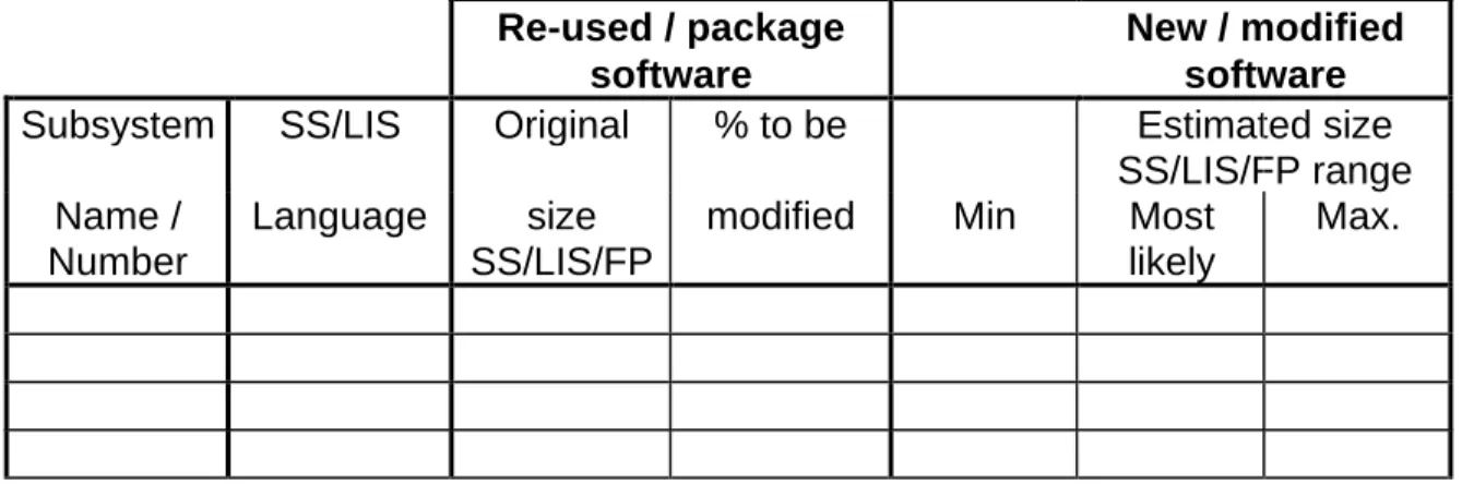
QSM use this size information to quantify the risk when estimating the time and effort to build software. We do this by requiring the size range to be estimated for each sub-system or module to be developed. Hence the size range inputs for a given development are expressed as shown in Figure 2.
Re-used / package software
New / modified software Subsystem SS/LIS Original % to be Estimated size
SS/LIS/FP range Name /
Number
Language size SS/LIS/FP
modified Min Most likely
Max.
Figure 2 : Sub-system Size Range Estimates
Referring to Figure 2 each sub-system is identified that corresponds to a functional area of the specification.
The development language to be used for implementation allows gearing factors to be determined for size range estimates given in forms other that ELOC or LIS. The gearing factor associated with each sub-system and language is then used to compute the expected size range in ESLOC or LIS.
Reused software identifies existing software that is to be modified and extended. The sub-system functionality may be met completely from existing “off the shelf” software. Today we find very few completely new software developments. Most developments are extensions of existing systems that require sub-systems to be modified or extended.
The sub-system size is expressed as a size range determined from the
specification. Where detailed specifications are available then the sub-system size range may be expected to be relatively small. On the other hand if the specifications lack detail in certain areas then the range may be wide.
These size uncertainties are used to quantify risk when estimating development time, effort, cost and reliability. Equally the size estimates and their uncertainty bounds provide the means of tracking progress as the software is being built. We normally suggest sub-systems are broken down wherever possible so that the most likely size does not exceed 3000 ELOC.
Sub-system Increment Dependence
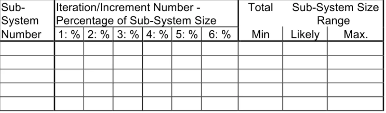
When incremental or iterative developments are planned then the table shown in Figure 3 is used to identify which sub-systems are to be realised in a given increment. The percentage of subsystem code estimated for each iteration allows identification of :
• increments that consist of a collection of entire sub-systems, in this case each sub-system is quantified as 100%
• increments that are made up of parts of sub-systems, here each sub-system is estimated as a percentage of the total sub-system size
Sub-System Iteration/Increment Number -Percentage of Sub-System Size Total Sub-System SizeRange Number 1: % 2: % 3: % 4: % 5: % 6: % Min Likely Max.
Figure 3 : Increment Dependency Table
Note that where increments are identified as consisting of a number of partial sub-systems this can mean that the first increment code of a given sub-system is expected to be revised and extended for following increments. This in turn
implies that the initial code can probably be expected to be changed as later increments are developed and hence re-testing can be expected for the growing number of earlier increments and the changed sub-systems .
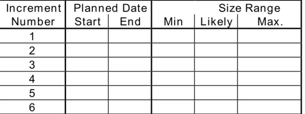
From the information given in Figure 3 it is possible to sum the total size range for each increment. Figure 4 sets out the simple form that captures the total size range of each increment.
This then becomes the basis for the high level tracking of the development of a given increment. The start date and end date of the increment plus the size can be used to monitor progress and determine the overall project progress.
Increment Planned Date Size Range
Number Start End Min Likely Max.
1 2 3 4 5 6
Figure 4 : Increment Plan and Size Range
An Instance of Increment Progress Tracking
To illustrate the use of the increment tracking we show in Figure 5 an example of following the progress of a development at the increment level using one of the QSM automated tools, SLIM-Control.
INCREMENT 1 (Cum) 0 2 4 6 8 10 12 14 S 1 2 3 4 5 6 7 8 9 S 1 2 7 8 9 INC1 (thousands) 1 2 3 4 5 6 7 8 9 10 11 12 13 14 *
Increment Plan :
Code Production
Reported
Cumulative Size
Size
Range
Bounds
Out of
Bounds
Traffic
Lights
Months
PLANNED INCREMENT : SIZE VERSUS TIME
Increment Size :
(Thousands ELOC)
Figure 5 : Tracking an Increment
Distributed and Incremental Development : What Is a Software Project Our work estimating and controlling software development involves a further variant that occurs in large organisations that have geographically separated sites. In these developments parts of an entire system are developed at one location while other parts are developed at different locations.
We are frequently asked “What is a Software Project”? under these conditions. The same question applies to software increments namely : “Is the project each part or increment at each location or is it the integration and testing of all the parts or increments?”.
For us the test is “Can a given part or increment be independently tested and accepted for operation?
If the answer is yes then the part or increment is treated as a project in its own right. Each part or increment is estimated and controlled separately including independent operational delivery and acceptance.
If the answer is no, then the sum of all the parts or increments is the project and each part or increment has to be integrated with other software before
independent testing and final operation. In this case the entire project is estimated for the sum of all the parts. However progress is tracked at the individual sub-system and increment level as well as the total for all the parts. Risk Assessment
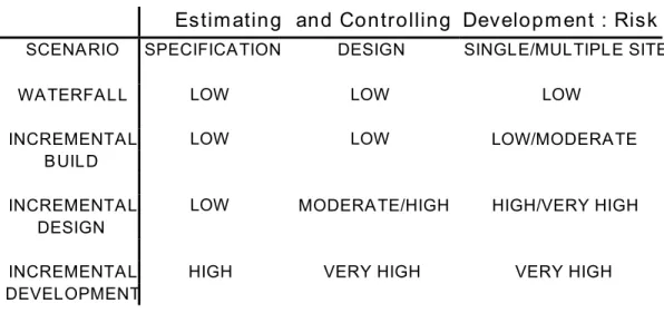
The development scenarios set out in Figure 1 are shown risk assessed in Table 1 below. As well as reflecting the risk from an incomplete design the table takes in to account the coupling between sub-systems and increments.
Higher risk arises where an increment is made up of sub-systems that are subsequently modified. The modified sub-system developed for a later
increment means the original increment must be regression tested to ensure the initial code is still correct.
Waterfall developments represent the lowest risk. Incremental build is equally low risk except when increments are developed using parts of sub-systems. This partial development of sub-systems leads to increased risk of rework. Incremental design increases the risk that the partial design may not satisfy later increments resulting in earlier work being scrapped and redone. Again this risk increases where increments require re-work of part completed sub-systems. Incremental development is entirely high risk. It assumes functional
specifications and design are extended with each “increment”. Hence there is no guarantee that the entire development will work. Equally it is only possible to estimate and control each increment treating each as a project.
Estimating and Controlling Development : Risk SCENARIO SPECIFICATION DESIGN SINGLE/MULTIPLE SITE
WATERFALL LOW LOW LOW
INCREMENTAL LOW LOW LOW/MODERATE
BUILD
INCREMENTAL LOW MODERATE/HIGH HIGH/VERY HIGH DESIGN
INCREMENTAL HIGH VERY HIGH VERY HIGH DEVELOPMENT
Table 1 : Development Scenario Risks Observations
Incremental “developments” offer advantages but carry risks. When considering the forms of development we find that it is beneficial to clarify the specific type of incremental approach being planned.
In many small business systems with low design complexity even the high risk incremental development is practical in order to meet tight development time scales. As the size and complexity of the development grows there is an increasing risk that the rework of the design may lead to software being re-written.
In addition the interdependency of increments and sub-systems has to be taken in to account when evaluating risks. There are fewer risks if an increment is made up of entire sub-systems that are not changed once developed.
Where increments are composed of elements from various sub-systems then more risk of rework arises. The later increments can require that the earlier code is amended and re-tested together with all the associated sub-systems in the earlier increment. We have found situations where this interdependency is so high that the final development resembles the traditional waterfall model in all essential respects.
From a software development estimating view point it is practical to consider the overall project as a single development for the waterfall model and for each of the incremental builds and incremental designs. However these last two need to be qualified by careful consideration of the interdependencies of increments and sub-systems. Where high interdependency occurs then the development
resembles the traditional waterfall model requiring reintegration and re-testing as the increments and sub-systems grow.
Distributed development over separate sites can be treated as increments in the same way with the qualification that each increment may be a separate project in its own right if it can be tested and accepted for independent operation. If all parts have to be integrated and tested together before independent operation then these are parts of a single development.
Where increments or parts are developed then these can be quantified, planned and tracked as part of a project.
To underline the risks that are associated with incremental development it is worth quoting the experience of an informed purchasing organisation regarding the problems they have encountered when dealing with suppliers.
“Do not track chaos. Sometimes suppliers call it incremental or parallel
development or sometimes even prototyping. It all means that suppliers do not (yet) know what they are doing or where they are aiming.” (Ref. 6)
Ref. 1 : Putnam L.H & Myers W Measures For Excellence Prentice Hall ISBN 0-13-567694
Ref. 2 : SEI Software Size Measurement with Application to Source Statement Counting : Carnegie Mellon Size Subgroup Software Metrics Definition Working Group Draft August 1991
Ref. 3: Carleton A.D., Park R.E., Goethert W.B, SEI Core Measures: Journal of the Quality Assurance Institute July 1994
Ref. 4 : Handboek van de Nederlandse Software Metrieken Gebruikers Associatie- Standaarisatie Definities/Telrichtlijnen FPA
Ref. 5 : KPN logistics Handboek Software Control Management : Kempff G.K Ref. 6 : Kempff G.K. Presentation at QSM European User Conference May 1996