Real-Time Supervisory Control for Power Quality Improvement of Multi-Area
Microgrids
Hashempour, Mohammad M.; Lee, Tzung-Lin; Savaghebi, Mehdi; Guerrero, Josep M.
Published in:I E E E Systems Journal
DOI (link to publication from Publisher): 10.1109/JSYST.2018.2823899
Publication date:
2019
Document Version
Accepted author manuscript, peer reviewed version Link to publication from Aalborg University
Citation for published version (APA):
Hashempour, M. M., Lee, T-L., Savaghebi, M., & Guerrero, J. M. (2019). Real-Time Supervisory Control for Power Quality Improvement of Multi-Area Microgrids. I E E E Systems Journal, 13(1), 864 - 874. [8340771]. https://doi.org/10.1109/JSYST.2018.2823899
General rights
Copyright and moral rights for the publications made accessible in the public portal are retained by the authors and/or other copyright owners and it is a condition of accessing publications that users recognise and abide by the legal requirements associated with these rights. ? Users may download and print one copy of any publication from the public portal for the purpose of private study or research. ? You may not further distribute the material or use it for any profit-making activity or commercial gain
? You may freely distribute the URL identifying the publication in the public portal ?
Take down policy
If you believe that this document breaches copyright please contact us at [email protected] providing details, and we will remove access to the work immediately and investigate your claim.
Real-Time Supervisory Control for Power Quality
Improvement of Multi-Area Microgrids
Mohammad M. Hashempour
, Tzung-Lin Lee, Member, IEEE, Mehdi Savaghebi, Senior Member, IEEE,
and Josep M. Guerrero, Fellow, IEEE
Abstract—In this paper, the power quality (PQ) improvement of
multi-area microgrids (MAMGs) is addressed. To this aim, miti-gation of voltage harmonics and unbalance is considered by using distributed generators (DGs) and active power filters (APFs) in a proper way. As a novel approach, the main goal of the proposed method is to pick out redundant APFs and/or significantly reduce of DGs and APFs compensation workload by making collaboration between areas toward integrated PQ improvement of the MAMG. To achieve the desired PQ indices of different areas, supervisory control is planned for proper utilization of available compensators in time. By supervisory control, harmonic propagation between areas and the system unbalance are dealt with and systemic PQ improvement of the MAMG is provided. To this aim, scheduling framework is used to track the PQ situation of each area. Eval-uation of the proposed control is carried out by a comprehensive simulation study in MATLAB/Simulink.
Index Terms—Active power filter (APF), distributed
gen-erator (DG), multi-area microgrid (MAMG), real-time power quality (PQ) tracking, supervisory control (SC), voltage unbal-ance/harmonic compensation.
I. INTRODUCTION
C
OMBINATION of distributed generators (DGs), energy storage systems, and loads in a small-scale grid forms a microgrid (MG). MGs may operate connected to the main grid (grid-connected) or isolated from that (islanded). As multifunc-tional converters, DGs interface converters can be controlled to supply power and improve power quality (PQ).Among many strategies proposed for voltage harmonic and unbalance compensation of the MG by proper control of DGs converters, some of them consider common point (CP) of loads or sensitive load bus and some others address the quality of DGs terminal [1]–[11] (a brief explanation of some approaches is discussed in [8]). However, PQ of other points except for the considered point might become distorted severely by these methods. In general, if voltage compensation occurs locally, the
Manuscript received August 6, 2017; revised February 17, 2018; accepted March 15, 2018. This work was supported by the Ministry of Science and Tech-nology of Taiwan under Grant 107-3113-E-110-001-. (Corresponding author:
Mohammad M. Hashempour.)
M. M. Hashempour and T.-L. Lee are with the Department of Electri-cal Engineering, National Sun Yat-Sen University, Kaohsiung 80424, Taiwan
(e-mail:,[email protected]; [email protected]).
M. Savaghebi is with the Department of Electrical Engineering, Karaj Branch,
Islamic Azad University, Karaj 31485-313, Iran (e-mail:,[email protected]).
J. M. Guerrero is with the Department of Energy Technology, Aalborg
Uni-versity, Aalborg DK-9220, Denmark (e-mail:,[email protected]).
Digital Object Identifier 10.1109/JSYST.2018.2823899
other points except for the considered compensating point might be distorted. This phenomenon is known as “whack a mole” [12]. Voltage distortion at DGs terminal might damage some consumers in electrical proximity of those areas so PQ improve-ment of both DGs terminal and CPs should be attended. Using active power filters (APFs) for PQ improvement is the subject of many research works, e.g., [13]–[26]. Simply, shunt APFs (which are much more popular than series one) inject proper harmonic and/or fundamental negative sequence current in the opposite phase of the undesired part of line current to cancel current distortion and consequently voltage harmonics and/or unbalance, respectively. However, based on the APF compen-sation effort, voltage quality at the points except for the APF installation point might be degraded [12]. To simultaneously compensate voltage harmonics of CP and DGs buses, DGs and APFs are used in a coordinated way in [8], while DGs inverters rated power is also considered in a compensation procedure. In [8], it is tried to reduce APFs rating in a construction phase of a new single-area MG.
With the exponential growth of distributed energy resources, the MG is becoming a multidirectional network interconnecting a vast range of consuming devices. As an effective approach to increase reliability and decrease dependence on energy storage systems, larger scale MGs interconnecting more DGs are recommended, since by extension of power sharing between DGs, it would be possible alleviation of the problems created due to unreliable renewable energy resources. Accordingly, PQ issue of such a wide system needs to be attended more since the PQ situation of a certain point (or area) might significantly affect the other points (or areas) PQ level due to harmonic propagation [27], [28]. Few literature works address the PQ of larger scale power systems [29]–[31]. For example, in [29], a double-resistive APF is proposed to attenuate voltage harmonics and suppress harmonic propagation in radial power systems respectively installed at the end feeder and at a specific place determined based on PQ concerns. The proposed method in [29] is not applicable in interconnected power systems. In [30], a long-feeder simulator-based APF is proposed to reduce harmonic propagation in closed-loop distribution feeders. The proposed APF is recommended to be installed at the middle electrical point of the system. Likewise, the proposed method in [30] cannot be used in interconnected power systems. In [31], an optimal utilization of DGs inverters (as compensators) is proposed. Taking into account the available capacity of each inverter, to utilize inverters toward harmonic suppression as
1937-9234 © 2018 IEEE. Personal use is permitted, but republication/redistribution requires IEEE permission. See http://www.ieee.org/publications standards/publications/rights/index.html for more information.
far as possible, a double-objective optimization approach is considered in [31]. Obviously, there would be no (or weak) compensation in case DGs are operated in full operation or renewable energy is unavailable.
Yet, integrated PQ improvement of larger scale power systems (regardless to topology) is not achievable in [29]–[31] since harmonic propagation is dependent on some uncertain factors such as loading condition and distribution lines [30]. As a result, there is no guarantee that all PQ indices of different points of a multi-area MG (MAMG) are tracked during the time. In other words, continuous PQ improvement of the MAMG, which is divisible based on PQ requirement of each area, as a unified system has not been addressed so far.
In line with previous efforts toward simultaneous PQ im-provement of DGs terminal and CPs, the present paper’s contri-butions can be listed as follows.
1) PQ improvement under the existing unbalance-nonlinear load condition.
2) PQ improvement of the interconnected MAMG while ar-eas are distinguished by their PQ requirements. As a novel approach, the proposed strategy is implementable in any topology of power systems.
3) The proposed strategy can be implemented either in a construction phase of a new MAMG or for operation of an established MAMG. The proposed method is able to increase the efficiency of APF placement that might carry out in the construction phase of the MAMG. In addition, the proposed method can be used to improve the PQ of new sensitive load buses (or CPs) without installation of a new APF in the respective buses in an established MAMG. It is because integrated PQ improvement of the MAMG is addressed utilizing available compensators.
4) Taking into consideration the loading condition of areas in a PQ improvement process so that the MAMG is improved by the least number of available compensators. Due to harmonic propagation and mutual effects of unbalances between areas, the loading condition of each area is of great importance and this concern is addressed by using a scheduling framework in the proposed method.
Noteworthy to mention that the paper approach can be con-sidered as a further step to the previous work [8] specialized for the MAMG that is a different scenario, entirely.
In what follows, the general scheme of the proposed control and CP compensation by DGs and APFs are described in Section II. Section III is dedicated to the proposed supervisory control (SC). Simulation study is provided in Section IV, and the paper is concluded in Section V.
II. GENERALSCHEME OF THEPROPOSEDCONTROL
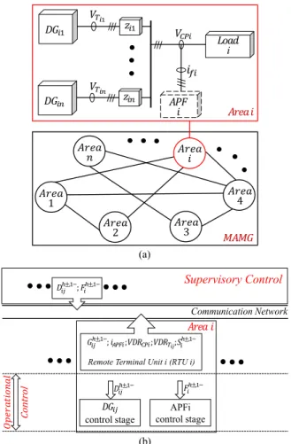
Fig. 1 illustrates an interconnected MAMG and the general structure of the proposed control. The areas of the MAMG are connected by interarea lines and each area might contain several DGs, APF, and a variety of loads (including linear, nonlinear, unbalanced, and unbalance-nonlinear loads). The subscriptijrepresents the jth power component in the ith area. Two points are represented in each area with subscripts Tij
Fig. 1. General scheme of the proposed control. (a) Power stage. (b) Control
stage.
(DGij terminal) and CPi as the coupling point of areas where
there might be high amount of loads including sensitive loads. In Fig. 1, voltage distortion rate (VDR) might be a collection of voltage unbalance factor (VUF), voltage total harmonic distortion (THD), and voltage individual harmonic distortion (VHD) including both positive and negative sequences of harmonic components. By remote terminal units,iAPFand VDR of all areas are calculated by the following equations [12]:
VHD= V h± rmso α Vrms1+o α ; VUF= V 1− rmso α Vrms1+o α . (1) THD= 1 V1 ∞ h=2 Vh2 = 1 V1 ˜ Vd2+ ˜Vq2 (2) iAPF= i1f ,dq− 2+ h=3,5,7 ihf ,dq± 2 (3) where Vrms1+o α, V 1− rmso α, and V h±
rmso α are fundamental positive
sequence, fundamental negative sequence, and hth harmonic components (positive and negative sequences) of voltage rms (α-axis in a stationary framework), respectively.V˜d andV˜q are
oscillatory components of voltage in the d- and q-axis, respec-tively, andV1 is the rms value of phase voltage (fundamental
Fig. 2. Equivalent circuit of a typical area in compensation point of view.
sequence and harmonic components of the filter output current in the dq framework. Thereafter, the VDR of CPi andTij is,
respectively, represented by VDRCPiand VDRTi j.
VDRCPi is recommended to be pretty low to provide high
quality of power for high amount of sensitive loads and reduce harmonic propagation between areas. Meanwhile, satisfactory VDRTi j should be considered based on the PQ indices
demined by the sensitivity of the loads located close to DGs ter-minals.
SC is used to suppress VDR of the MAMG by proper ex-ploitation and management of DGs and APFs so that the least number of them are used. Beside power sharing, the commands from SC put into effect using operational control. Operational control consists of DGs and APFs control stages. Comprehen-sive details corresponding to the control stage of DGs and APFs are available in [7], [8], and [14]. Yet, CP compensation of each area might be carried out by the cooperation of respective DGs and APFs.
Fig. 2 shows the equivalent circuit of a typical area from compensation point of view. DGs, as voltage-controlled voltage source inverters, and APFs, as current-controlled current source inverters, try to compensate CP.VVDRCPi andVVDRT i j (voltage
distortion components at CPiandTij, respectively) should be
compensated. For instance, the negative sequence of the third harmonic component of CPi voltage might be considered as
VVDRCPi.YLoad andYLineare load and line admittances,
respec-tively.
From Fig. 2, it can be deduced
Vf =VVDRT i j − is Yeq (4) (Vf −VVDRCPi)·YLoad=iL (5) iL =is+if. (6)
Using the above-mentioned equations, the following equation can be easily derived:
VVDRT i j −VVDRCPi ·YLoad= (1 +K)·iL −K·if (7)
whereK=YLoad/YLine. In addition, the following function can be applied for DGs and APF:
VVDRT i j =GDG·(−VVDRCPi) (8)
if =GAPF·iL (9)
where GDG andGAPF are, respectively, compensation gain of DG and APF. Replacing (8) and (9) into (7), the following
Fig. 3. CP compensation by DGs or APF.
Fig. 4. CP compensation by the cooperation of DGs and APF.
equation is achieved:
(GDG+ 1)·VVDRCPi = (1 +K−K·GAPF)·VL (10)
whereVL =iL/YLoad.
Normally,YLineYLoad (orK1) [5]. Thus,K is negli-gible in comparison with 1 and the following equation can be achieved with a good accuracy:
(GDG+ 1)· VVDRCPi
VL = (1−K·GAPF).
(11) In (11), the termVVDRCPi/VLresults VDRCPi. Based on (11),
Fig. 3 illustrates CP compensation by DG and APF. When
GDG= 0, compensation is only carried out by the APF, and whenGAPF= 0, compensation is merely carried out by the DG. VDRCPi is attenuated when DG or APF compensation gain is
increased. Hereby, it can be induced that the vertical axis of Fig. 3 is the compensation rate of CP.
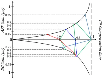
As mentioned before, CP compensation might be carried out by so called the “cooperation” of DGs and APF. To better illustrate the cooperation, another interpretation of (11) is represented in Fig. 4. In this figure, compensation gain of CP by DG and APF is shown in per unit. In other words, DG and APF compensation gains are theatrically normalized based on their maximum values. Hereby, it would be possible assuming a general relationship between compensation effort and the percentage of VDR. This way, complete compensation can be estimated as VDR=0%; likewise no compensation can be
Fig. 5. General scheme of supervisory control.
estimated as VDR=100%. It should be mentioned that these estimations are helpful for better realization of the cooperation although they are achieved by general assumptions.
Briefly, based on the cooperation principle, CP compensation rate is properly shared between DG and APF while DG is prior to APF. The sharing ratio is determined according to VDRTi j.
Typ-ically, if 60% of complete compensation (reducing VDRCPto zero) is determined to yield the PQ indices of CPi(VDRCPiref), based on the cooperation principle, it might be shared between APF and DG by the ratio of 1:3 (red lines in Fig. 4). For in-stance, considering VDRCPiref=THDCPiref= 5%, to reduce THDCPifrom the current value to 5%, the required
compensa-tion effort, e.g., 0.8 p.u., might be shared between DG and APF by the ratio of 1:1.67 (blue lines in Fig. 4). Anyway, APFiand DGijcompensation gains are assigned asSih±,1−andGhij±,1−, respectively [8].
III. PROPOSEDSUPERVISORYCONTROL
Generally speaking, SC manages the compensation process so that PQ indices of allTijand CPs of the MAMG are achieved
by the least number of DGs and APFs when redundant compen-sators are picked out. In other words, based on loading condi-tion and VDR of different points of the MAMG, SC provides a proper arrangement of available compensators to suppress VDR and obtain PQ indices so that no extra compensator is operated. It means that the arrangement is set in accordance with the VDR of the MAMG.
Note that the scenario here is completely different from a single-area MG since there are multiple areas connected to-gether; therefore, PQ improvement of each area might signifi-cantly affect other areas’ PQ level [12], as shown in Section IV. Simply, SC responsibility is to get benefit from this effect and cause further reduction in the number of the compensators op-erating in time. Remember that the first reduction is achieved by the cooperation between DG(s) and APF of each area. To meet SC contribution and track load changes(VDRTi j, VDRCPi)of
all areas, the paper approach is to implement SC in a time-series-based model (so called “scheduling framework”), as represented in Fig. 5 [32].
According to Fig. 5, SC can be operated in two modes: CP compensation mode (PCM) andTijcompensation mode (TCM).
Note that these modes take place in a series while the PCM is prior to the TCM. In other words, primarily SC improves all CPs, then it deals withTijwhen all CPs meet specified PQ indices.
A. SC in the PCM
As shown in Fig. 1, the data acquired by remote terminal units are transferred to SC by a low-bandwidth communication
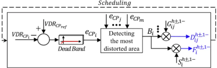
Fig. 6. Supervisory control in the PCM.
network. Fig. 6 shows SC in the PCM. First, all VDRCPi are
compared with the reference value. Noteworthy that PQ indices of all CPs are set to the same value to make effective collab-oration between areas. The reference PQ indices might be set based on the most sensitive CP; however, high level of PQ is preferred for CPs to achieve more efficient collaboration. Then, the errors(eCPi)are fed to the detection block. The following
simple if-else loop function is considered in this block: For i= 1 :m; For j= 1 :m&j=i
ifeCPi > eCPj; Bi= 1;
else; Bi= 0; break; End;
End (F1)
where m is the number of areas.
Based on F1, the area with the highest VDRCP is detected, then the command signalBi= 1is specified for that area. Note
that other areas’ respective signals areBj = 0. It means that the
CP compensation of those areas is not initiated yet. The signals are multiplied with the respective DGs and APF compensation gains generated by the cooperation (i.e.,Sih±,1−andGhij±,1−).
The final gains are represented asDhij±,1−(DGijcompensation
gain) andFih±,1−(APFicompensation gain) in Figs. 1 and 6. The new gains are transferred to operational control. As shown in Fig. 6, SC regenerates the commands during time. In other words, after each time period, the signalsDhij±,1−andFih±,1−
are regenerated and sent to the operational control (see Fig. 1), meaning that the next area starts to compensate respective CP if it is needed. By this policy, SC in the PCM meets its obligation that is reducing compensators rating. In fact, PQ improvement of the considered area can significantly reduce the workload of the compensators in other areas. Consequently, in comparison with a conventional strategy that the compensators of the power system are individually operated merely based on the VDR of an installation point, there might be some spare compensators by this workload reduction. Using the proposed SC, the redundant compensators are automatically picked out from a compensation process. In addition, it is planned in SC shutting down of low operating APFs and transferring their compensation burden to other APFs (in the other areas) operating in normal operation. It results in further reduction in the applied compensators (more details are discussed below). That is why we say “collaboration” between areas.
The dead band block in Fig. 6 is for removing compensated CPs from the loop and prohibiting CP compensation of those areas with no violation from VDRCPiref. Furthermore, operation
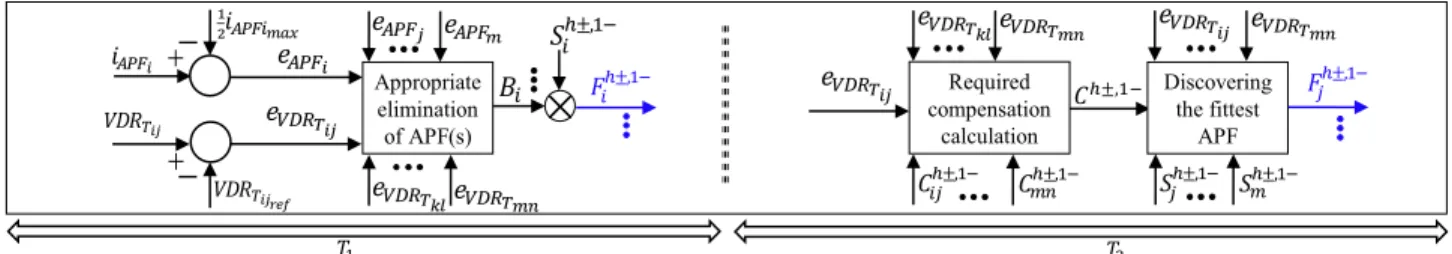
Fig. 7. Supervisory control in the TCM.
of SC in the PCM terminates when all CPs meet specified PQ indices. In further details, in case of no violation of the indices from the beginning, SC in the PCM would be bypassed (due to the dead band). In that case, according to the cooperation principles, CP compensation might be carried out only by DGs. Considering all possible cases, if we have significant increase at VDRCPi due to nonlinear load increase, an additional area
might join to the compensation process according to PCM con-trol function (F1). In this case, other areas’ collaboration had not been sufficient to meet VDRCPiref. On the other hand, in case of decreasing VDRCPi, there might be a decrease in compensators
rating as explained below. B. SC in the TCM
After the PCM, SC proceeds with the TCM. Fig. 7 shows SC in the TCM. Generally speaking, the main purpose of SC in the TCM is picking out redundant APFs by making collaboration between operating APFs scattered in the MAMG. Simply, the strategy here is to remove low operating APFs from the com-pensation process and devolving their burden to one of them located in the area with the highest VDRTi j. It is achievable by using two successive control phases: appropriate elimination of APF(s) as phase I (T1in Fig. 7) and counteracting the reduced
compensation effort as phase II (T2in Fig. 7).
1) Phase I of the TCM (T1): It is assumed that those APFs
operating in less than half of their rated power are low operating filters. Of course, this assumption can be easily modified ac-cording to the technical concerns of each APF. Based on Fig. 7,
eAPFi andeVDRT i j are calculated and fed to the block
“appro-priate elimination of APF(s).” The following math function is applied in this block:
For i= 1 :m; For j= 1 :n
ifeAPFi ≤0 &eVDRT i j ≤0; Bi = 0;
else; Bi= 1; break; End;
End (F2)
where n is the number ofTij in the considered area. Based on
F2, after detecting low operating APF(s), shutdown command
(Bi= 0)is applied to the gain of the extracted APF(s) to be
eliminated from the compensation process[see Figs. 1(b) and 7]. Note that the inequality constrainteVDRT i j ≤0joins the loop
in the next time period, basically.
2) Phase II of the TCM (T2): By the removal of one or more
APFs, VDR at one or more ofTij will be increased especially
thoseTijbeing in the same area with the removed APF(s) due
to smaller electrical distance between the respective CP and
Tij. To tackle this inconsistency, one of the APFs is called to
counteract the reduced compensation effort.
First,eVDRT i j is fed to the block “required compensation cal-culation.” Then,Ch±,1−(see Fig. 7), as the total compensation effort required by all DGs due to the removal of one or more APFs, can be calculated by F3
Ch±,1−= 0; For i= 1 :m; For j= 1 :n
ifeVDRT i j >0; Ch±,1−=Ch±,1−+Cijh±,1−; else; break; End
End. (F3)
Generally, the fittest APF for neutralization is the one located in the area with the highesteVDRT i j due to the smallest electrical distance between Tij and the APF [Zij in Fig. 1(a)]. Thus,
detecting the fittest APF is carried out by using the following math function (see Fig. 7):
For i= 1 :m; For j= 1 :n; For k= 1 :m&k=i;
For l= 1 :n&l=j
ifeVDRT i j > eVDRT k l; Sih±,1−=Ch±,1−+Sih±,1−; else; Shi±,1−=Sih±,1−; break; End; End
End; End. (F4)
Based on F4, the fittest APF is detected then its compensation gain is increased byCh±,1−, while there is no change for the rest. Note that only those APFs that were candidates for appropriate elimination (F2), are in the game. In fact, these APFs had been operating in low operation so they are more likely to have enough capability to counteract the total reduced compensation effort. However, in case of overloading the fittest APF, it is axiom that compensation effort of the APF would be limited to its maximum operation.
In rare cases, if the fittest APF is operating in the maximum operation, SC continues with the next time period (see Fig. 5), the PCM is bypassed, and finally, since there is one or more
eVDRT i j >0, the fittest removed APF returns to the
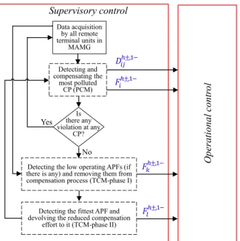
Fig. 8. Proposed control in flowchart configuration.
C. Overview of SC
Fig. 8 presents a flowchart of the proposed control. In total, there are two important points regarding SC: First, due to higher current propagation of a fundamental negative sequence in com-parison with harmonic components (in order to lower interarea line impedance at a fundamental component), SC individually deals with VUF and THD (or VHD) at the same time. Second, three successive steps are contrived in SC to reduce compen-sators rating:
1) The first reduction is obtained by making cooperation between DGs and APFs.
2) The second reduction occurs by making collaboration be-tween areas (compensating areas sequentially; PCM). 3) The third reduction gains making collaboration between
APFs of areas (TCM).
IV. SIMULATIONSTUDY
The test MAMG is shown in Fig. 9. Nominal voltage and frequency of the system are 230 V (per-phase rms value) and 50 Hz, respectively, and the switching frequency of DGs and APFs inverters is 10 kHz. To entirely evaluate the proposed control in different areas with different load conditions, four areas with different PQ requirements ofTijare considered in the system. It
should be mentioned that the considered MAMG system is the most complex system with four areas. Hereby, other possible configurations of the four-area MG (also three-area, two-area, and single-area MGs) can be realized as the subsystems of the considered system.
Diode rectifier is used to make nonlinear load as it is con-figured in Fig. 10. Thus, by disconnecting one phase of the nonlinear load, there will be unbalanced-nonlinear load. In ad-dition, to avoid complexity, APFs are considered the same.
Fig. 9. Test system.
Fig. 10. Configuration of load i.
TABLE I
POWERQUALITYREFERENCES
Further to voltage unbalance suppression, compensation of both positive and negative sequences of third, fifth, and seventh harmonics (the main orders) ofTijand CPs voltages is carried
out. PQ references ofTijand CPs are presented in Table I. In the
present simulation study, PCM-scheduling,T1, andT2 (related
to the TCM) are set to 5 s. Note that these terms are set to a short value to reduce simulation run time. Three scenarios are planned to evaluate SC in PCM and TCM under different loading conditions. Note that these scenarios are only distinguished by the loading condition of the MAMG, while control and power parameters are the same as presented in Table II.
A. First Scenario, SC in the PCM
In this scenario, areas 1 and 2 contain unbalance-nonlinear and linear loads and areas 3 and 4 include nonlinear and lin-ear loads. Fig. 11 shows VDRCPiand VDRTi j. Among all CPs,
TABLE II
TESTSYSTEMPARAMETERS
Fig. 11. VDRCPs(PCM). (a) THD. (b) HD. (c) VUF.
based on Fig. 11(a), att=5 s, the highest VDR (both THD and VUF) belongs to CP1. Thus, compensation of area 1 is carried out in period 1 so VDRCP1ref and VDRT11,2ref are achieved based on Fig. 11(b). At the end of period 1, CP4 and CP2 are in the highest THD and VUF, respectively. Therefore, har-monic compensation of CP4and voltage unbalance suppression of CP2 are done in period 2. It can be seen that HDCP4 ref, THDT41 ref, VUFCP2 ref, and VUFT21 refare achieved in this pe-riod [see Fig. 11(b)]. During periods 3 and 4, only harmonic compensation of areas 2 and 3 is carried out, respectively. It is shown that HDCP2 ref and THDT21 refin period 3 and HDCP3 ref and THDT31 refin period 4 are obtained. Note that before period 1, there were VUF-violation at areas 3 and 4; however, after pe-riod 2, there is no violation at these areas although neither their DGs nor their APFs are used for VUF suppression. By precise exploration of Fig. 11, two notes can be deduced.
1) First, PQ of other areas except for the considered area is also improved while compensation is not initiated for them. For example, from period 1 to period 3, THDCP3is decreased from 4.5% to less than 2.5% while harmonic compensation has not been initiated in area 3 (it is the same for VUF suppression).
2) Second, since VDRCPireduction is initiated in the
respec-tive period, corresponding VDRTi j is increased to the
reference value based on Table I. Simply, it can be seen in Fig. 11(a) that in the last period (20<t<25), all the curves less than 1% are related to CPs and the others are related to DGs terminals. It shows that the cooperation between APFs and DGs is accomplished properly since compensation sharing is done so that DGs are prior to APFs (see Section II).
B. Second Scenario, SC in the TCM (Unbalance-Nonlinear Load Reduction)
In this scenario, areas 1–3 contain unbalance-nonlinear and linear loads, while area 4 includes nonlinear and linear loads. Fig. 12 represents voltage harmonics of the system. Beforet=
8 s, the reference values of CPs and Tijs are achieved and SC
proceeds with the TCM. At t=8 s, an unbalance-nonlinear load reduction (RN L2 from 33 to 100Ω) occurs at CP2. In this
situation (t=10 s), APF2, APF3, and APF4are operated in low operation situation, while APF1is operated in normal operation so shutdown commands(B2 =B3 =B4 = 0)are sent to APF2
to APF4 inT1 (10<t<15). Accordingly, VDRT21, VDRT31,
and VDRT41are increased. It is because APF2, APF3, and APF4
are switchedOFFand only DG21, DG31, and DG41compensate
CP2, CP3, and CP4, respectively. On the other hand, VDRT11 (both THDT11 and VUFT11) almost remains without change aftert=10 s since APF1 is operated duringT1. At the end of
T1 (t=15 s),T21 is detected as the terminal with the highest
violation from the reference value (see Fig. 12). Thus, APF2(the closest APF to T21) is chosen as the fittest APF to counteract
the reduced compensation effort. Fromt=15 s(T2), APF2 is
returned to the compensation process, while the compensation effort of APF3and APF4 is added to the compensation effort of
Fig. 12. VDRT ijwhen SC is in the TCM (scenario 2).
APF2. From Fig. 12, it can be seen that since APF2is returned to the compensation process, all the PQ indices (including area 3 and area 4) are achieved. Note that APF3and APF4are switched
OFF. Meanwhile, VDRT1 1 is almost unchanged since area 1
does not contribute in the collaboration between APFs due to SC principles (see Section III). In addition, VDRCPshave not been changed because there have not been any violation from any CP.
It should be mentioned that VUF of all CPs and DGs terminals is in the allowable range so no collaboration between areas is required in this regard[see Fig. 12(b)]. Note that duringT1that
APF2 is switched OFF, VUFT21 is increased but it is still in
the allowable range. Therefore, duringT2that APF2is returned
to the compensation process, VUFT21 is also returned to the
previous value (T1) since APF2does not compensate unbalanced
voltage.
As a more tangible figure, Fig. 13 shows voltage and current waveforms of different points of the MAMAG when SC is in the TCM. Comparatively, it can be seen that CP4-current is under the lower unbalanced condition. It is because area 4 is free of unbalanced load; however, due to the imbalance of the MAMG as a unified system, CP4-current is slightly unbalanced.
In addition, T21 voltage waveform at t=15 s is severely
distorted in comparison with those at the timest=10 and 20 s. It is due to the fact that APF2is switchedOFFduringT1so DG21
is the only compensator of area 2 during this time period (see Fig. 12). As a result, the DG compensation effort is increased; accordingly, the DG voltage distortion is increased. Generally, lower current and voltage distortion of CPs compared with those ofTijs can be seen. It is because CPs PQ level is higher than
that ofTijs.
Fig. 13. Voltage and current waveforms (scenario 2). Rows up to down. (a)
CP1, CP3,T11,T21,T41. (b) CP2, CP4,T12,T31.
C. Third Scenario, SC in the TCM (Unbalance-Nonlinear Load Increase)
Like the second scenario, in the third scenario, areas 1–3 contain unbalance-nonlinear and linear loads when area 4 in-cludes nonlinear and linear loads. As shown in Table II, the second scenario loading condition is followed by the third
Fig. 14. VDRT ijwhen SC is in the TCM (scenario 3).
scenario; therefore, APF1 and APF2 are ON when the com-pensation burden of APF3 and APF4is devolved to APF2.
Fig. 14 shows VDR at different points of the system. At
t=6 s, there is a severe increase in the unbalance-nonlinear load of area 3 (RN L3 from 40 to 13Ω). Thus, APF2 workload
is increased. However, it is in the maximum operation during
T2, as a result, area 2 (APF2) collaboration with area 3 (APF3)
is limited. Accordingly,T31-VDR (both VHD and VUF) is
in-creased during this period (see Fig. 14). Finally, at t=10 s, since there is a violation from a DG terminal (T31), the
respec-tive APF (that is, APF3 due to closeness toT31) is returned to
the compensation process based on F2 control function. Note that the PCM is bypassed since there is no violation from any VDRCP ref even from VDRCP2 ref (see Fig. 14). It can be seen that since APF3 is returned to the compensation process, the violations are removed. It is in the situation that the VDR of the other areas remains unchanged because it does not play any role in the new collaboration between areas 2 and 3.
Fig. 15 shows DG31 and DG41 output currents. As expected from Fig. 14, since APF3 is operated, the negative sequence of the fundamental component of current atT31 is decreased
because DG31 workload is decreased. Considering harmonic currents ofT31, it can be seen that the fifth order of harmonic
current is decreased, while the seventh order is increased. It shows that there had been a violation at VHD of the fifth order. Even though the seventh order of VHD is increased, this pa-rameter is still in the allowable range[see Fig. 14(a)]. However, based on Fig. 15, the output current of DG41remains unchanged as it was expected from Fig. 14. In what follows, a brief sum-mary is presented demonstrating the paper contribution by the simulation study.
Fig. 15. DGs output current (α-axis in the stationary framework); Blue lines:
DG31, Red lines: DG41. (a) Fundamental negative sequence. (b) Negative sequence of the fifth harmonic. (c) Positive sequence of the seventh harmonic.
Based on the loading condition of each scenario, from nine compensators (five DGs and four APFs) in the test system:
1) For VUF suppression
a) In the first scenario, DG31, DG41, APF3, and APF4 are removed from the compensation process. b) In the second scenario, APF2, APF3, and APF4 are
removed from the compensation process.
c) In the third scenario, APF4 is removed from the compensation process.
2) For voltage harmonic mitigation
a) In the first scenario, all nine compensators are uti-lized.
b) In the second scenario, APF3and APF4are removed from the compensation process.
c) In the third scenario, APF4 is removed from the compensation process.
Noteworthy to remind that by the conventional method, all nine compensators are operated since no plan is contrived in the conventional method reducing compensators rating based on VDR of the MAMG.
V. CONCLUSION
A real-time SC scheme is proposed in this paper to improve the PQ of an MAMG when the areas PQ requirements are dif-ferent. Both DGs terminal and CP of each area are attended in PQ improvement. Voltage unbalance and harmonic compen-sation, including positive and negative sequences of selected harmonics, are addressed in the proposed method. The main contribution of the proposed method is applying an efficient ar-rangement of available compensators in the compensation pro-cess so that the least number of them are used for integrated PQ improvement of the MAMG. To this aim, DGs inverters and APFs are considered as compensators. Briefly, three items are influential to develop the best arrangement: the coopera-tion between DG(s) and APF of each area, the collaboracoopera-tion between areas and the collaboration between the APFs of areas.
Furthermore, the arrangement is adaptively modified based on the VDR of the MAMG. The proposed method is evaluated by MATLAB/Simulink when a complex four-area MG is consid-ered as the test system.
REFERENCES
[1] M. Hojo, Y. Iwase, T. Funabashi, and Y. Ueda, “A method of three-phase balancing in microgrid by photovoltaic generation systems,” in Proc. 13th
Power Electron. Motion Control Conf., 2008, pp. 2487–2491.
[2] P.-T. Cheng, C.-A. Chen, T.-L. Lee, and S.-Y. Kuo, “A cooperative im-balance compensation method for distributed-generation interface con-verters,” IEEE Trans. Ind. Appl., vol. 45, no. 2, pp. 805–815, Mar./Apr. 2009.
[3] M. Savaghebi, A. Jalilian, J. C. Vasquez, and J. M. Guerrero, “Secondary control scheme for voltage unbalance compensation in an islanded droop-controlled microgrid,” IEEE Trans. Smart Grid, vol. 3, no. 2, pp. 797–807, Jun. 2012.
[4] L. Meng, F. Tang, M. Savaghebi, J. C. Vasquez, and J. M. Guerrero, “Tertiary control of voltage unbalance compensation for optimal power quality in islanded microgrids,” IEEE Trans. Energy Convers., vol. 29, no. 4, pp. 802–815, Dec. 2014.
[5] M. Cirrincione, M. Pucci, and G. Vitale, “A single-phase DG generation unit with shunt active power filter capability by adaptive neural filtering,”
IEEE Trans. Ind. Electron., vol. 55, no. 5, pp. 2093–2110, May 2008.
[6] N. Pogaku and T. C. Green, “Harmonic mitigation throughout a distribu-tion system: A distributed-generator-based soludistribu-tion,” IEE Proc., Gener.,
Transm. Distrib., vol. 153, no. 3, pp. 350–358, May 2006.
[7] M. Savaghebi, A. Jalilian, J. C. Vasquez, and J. M. Guerrero, “Secondary control for voltage quality enhancement in microgrids,” IEEE Trans. Smart
Grid, vol. 3, no. 4, pp. 1893–1902, Dec. 2012.
[8] M. M. Hashempour, M. Savaghebi, J. C. Vasquez, and J. M. Guerrero, “A control architecture to coordinate distributed generators and active power filters coexisting in a microgrid,” IEEE Trans. Smart Grid, vol. 7, no. 5, pp. 2325–2336, Sep. 2016.
[9] J. He and Y. W. Li, “Hybrid voltage and current control approach for DG-grid interfacing converters with LCL filters,” IEEE Trans. Ind. Electron., vol. 60, no. 5, pp. 1797–1809, May 2013.
[10] Q. Liu, Y. Tao, X. Liu, Y. Deng, and X. He, “Voltage unbalance and harmonics compensation for islanded microgrid inverters,” IET Power
Electron., vol. 7, no. 5, pp. 1055–1063, May 2014.
[11] J. He, Y. W. Li, C. Wang, and B. Liang, “Simultaneous microgrid volt-age and current harmonics compensation using coordinated control of dual-interfacing-converters,” IEEE Trans. Power Electron., vol. 32, no. 4, pp. 2647–2660, Apr. 2017.
[12] P. Jintakosonwit, H. Akagi, H. Fujita, and S. Ogasawara, “Implementation and performance of automatic gain adjustment in a shunt-active filter for harmonic damping throughout a power distribution system,” IEEE Trans.
Power Electron., vol. 17, no. 3, pp. 438–447, May 2002.
[13] P.-T. Cheng and T.-L. Lee, “Distributed active filter systems (DAFSs): A new approach to power system harmonics,” IEEE Trans. Ind. Appl., vol. 42, no. 5, pp. 1301–1309, Sep./Oct. 2006.
[14] T. L. Lee, J. C. Li, and P. T. Cheng, “Discrete frequency tuning active filter for power system harmonics,” IEEE Trans. Power Electron., vol. 24, no. 5, pp. 1209–1217, May 2009.
[15] F. Barrero, S. Martinez, F. Yeves, F. Mur, and P. M. Mart´ınez, “Universal and reconfigurable to UPS active power filter for line conditioning,” IEEE
Trans. Power Del., vol. 18, no. 1, pp. 283–290, Jan. 2003.
[16] K. Wada, H. Fujita, and H. Akagi, “Considerations of a shunt active filter based on voltage detection for installation on a long distribution feeder,”
IEEE Trans. Ind. Appl., vol. 38, no. 4, pp. 1123–1130, Jul./Aug. 2002.
[17] X. Sun, R. Han, H. Shen, B. Wang, Z. Lu, and Z. Chen, “A double-resistive active power filter system to attenuate harmonic voltages of a radial power distribution feeder,” IEEE Trans. Power Electron., vol. 31, no. 9, pp. 6203–6216, Sep. 2016.
[18] P. Acuna, L. Moran, M. Rivera, J. Dixon, and J. Rodriguez, “Improved active power filter performance for renewable power generation systems,”
IEEE Trans. Power Electron., vol. 29, no. 2, pp. 687–694, Feb. 2014.
[19] J. C. Alfonso-Gil, P. Emilio Perez, C. Arino, and H. Beltran, “Optimization algorithm for selective compensation in a shunt active power filter,” IEEE
Trans. Ind. Electron., vol. 62, no. 6, pp. 3351–3361, Jun. 2015.
[20] T.-F. Wu, H.-C. Hsieh, C.-W. Hsu, and Y.-R. Chang, “Three-phase
three-wire active power filter with D-Σdigital control to accommodate
filter-inductance variation,” IEEE J. Emerging Sel. Topics Power Electron., vol. 4, no. 1, pp. 44–53, Mar. 2016.
[21] H. Yi et al., “A source-current-detected shunt active power filter control scheme based on vector resonant controller,” IEEE Trans. Ind. Appl., vol. 50, no. 3, pp. 1953–1965, May/Jun. 2014.
[22] P. Kanjiya, V. Khadkikar, and H. H. Zeineldin, “Optimal control of shunt active power filter to meet IEEE Std. 519 current harmonic constraints under nonideal supply condition,” IEEE Trans. Ind. Electron., vol. 62, no. 2, pp. 724–734, Feb. 2015.
[23] L. Herman, I. Papic, and B. Blazic, “A proportional-resonant current controller for selective harmonic compensation in a hybrid active power filter,” IEEE Trans. Power Del., vol. 29, no. 5, pp. 2055–2065, Oct. 2014. [24] S. Biricik, S. Redif, C. Ozerdem, S. K. Khadem, and M. Basu, “Real-time control of shunt active power filter under distorted grid voltage and unbalanced load condition using self-tuning filter,” IET Power Electron., vol. 7, no. 7, pp. 1895–1905, Jul. 2014.
[25] Z. Shu, M. Liu, L. Zhao, S. Song, Q. Zhou and X. He, “Predictive harmonic control and its optimal digital implementation for MMC-based active power filter,” IEEE Trans. Ind. Electron., vol. 63, no. 8, pp. 5244–5254, Aug. 2016.
[26] R. Panigrahi and B. Subudhi, “Performance enhancement of shunt active
power filter using a kalman filter-based H∞control strategy,” IEEE Trans.
Power Electron., vol. 32, no. 4, pp. 2622–2630, Apr. 2017.
[27] H. Akagi, “Control strategy and site selection of a shunt active filter for damping of harmonic propagation in power distribution system,” IEEE
Trans. Power Del., vol. 12, no. 2, pp. 354–363, Jan. 1997.
[28] E. J. Currence, J. E. Plizga, and H. N. Nelson, “Harmonic resonance at a medium-sized industrial plant,” IEEE Trans. Ind. Appl., vol. 31, no. 4, pp. 682–690, May/Jun. 1995.
[29] X. Sun, R. Han, H. Shen, B. Wang, Z. Lu, and Z. Chen, “A double-resistive active power filter system to attenuate harmonic voltages of a radial power distribution feeder,” IEEE Trans. Power Electron., vol. 31, no. 9, pp. 6203–6216, Sep. 2016.
[30] X. Sun et al., “Study of a novel equivalent model and a long-feeder simulator-based active power filter in a closed-loop distribution feeder,”
IEEE Trans. Ind. Electron., vol. 63, no. 5, pp. 2702–2712, May 2016.
[31] Z. Zeng, H. Yang, S. Tang, and R. Zhao, “Objective-Oriented power quality compensation of multifunctional grid-tied inverters and its application in microgrids,” IEEE Trans. Power Electron., vol. 30, no. 3, pp. 1255–1265, Mar. 2015.
[32] A. Saint-Pierre and P. Mancarella, “Active distribution system manage-ment: A dual-horizon scheduling framework for DSO/TSO interface under uncertainty,” IEEE Trans. Smart Grid, vol. 8, no. 5, pp. 2186–2197, Sep. 2017.
Mohammad M. Hashempour received the B.S.
de-gree in solid status physics and the M.S. dede-gree in electrical engineering from Islamic Azad University, Tehran, Iran, in 2008 and 2014, respectively. He is currently working toward the Ph.D. degree at the Na-tional Sun Yat-Sen University, Kaohsiung, Taiwan.
His research interests include multilevel con-verters, power conversion, and power quality of microgrids.
Tzung-Lin Lee (S’04–M’08) received the B.S.
de-gree from Chung Yuan Christian University, Taoyuan, Taiwan, in 1993, the M.S. degree from the National Chung Cheng University, Chiayi, Taiwan, in 1995, and the Ph.D. degree from the National Tsing Hua University, Hsinchu, Taiwan, in 2007, all in electrical engineering.
Since Aug. 2008, he has been with the Department of Electrical Engineering, National Sun Yat-Sen Uni-versity, Kaohsiung, Taiwan, where he is currently an Associate Professor. His research interest focuses on utility applications of power electronics.
Mehdi Savaghebi (S’06–M’15–SM’15) was born in
Karaj, Iran, in 1983. He received the B.Sc. degree from the University of Tehran, Tehran, Iran, in 2004, and the M.Sc. and Ph.D. degrees with highest hon-ors from Iran University of Science and Technology, Tehran, Iran, in 2006 and 2012, respectively, all in electrical engineering.
From 2007 to 2014, he was a Lecturer with the Electrical Engineering Department, Karaj Branch, Is-lamic Azad University (KIAU), Karaj, Iran. He was a Postdoc Fellow with the Department of Energy Tech-nology, Aalborg University, Aalborg, Denmark, from 2014 to 2017. Currently, he is an Assistant Professor with KIAU. His main research interests include distributed generation systems, microgrids, power quality, Internet of Things, and smart metering.
Dr. Savaghebi has been a Guest Editor of Special Issue on Power Quality in
Smart Grids, IEEE TRANSACTIONS ONSMARTGRID. He is a Member of
Tech-nical Committee of Renewable Energy Systems, IEEE Industrial Electronics.
Josep M. Guerrero (S’01–M’04–SM’08–F’15)
re-ceived the B.S. degree in telecommunications engi-neering, the M.S. degree in electronics engiengi-neering, and the Ph.D. degree in power electronics from the Technical University of Catalonia, Barcelona, Spain, in 1997, 2000, and 2003, respectively.
Since 2011, he has been a Full Professor with the Department of Energy Technology, Aalborg Univer-sity, Aalborg, Denmark, where he is responsible for the Microgrid Research Program. From 2012, he is a Guest Professor with the Chinese Academy of Sci-ence, Beijing, China, and Nanjing University of Aeronautics and Astronautics, Nanjing, China; from 2014, he is a Chair Professor with Shandong University, Jinan, China; from 2015, he is a Distinguished Guest Professor with Hunan University, Changsha, China; and from 2016, he is a Visiting Professor Fellow with Aston University, Birmingham, U.K., and a Guest Professor with Nan-jing University of Posts and Telecommunications, NanNan-jing, China. His research interests focus on different microgrid aspects, including power electronics, dis-tributed energy-storage systems, hierarchical and cooperative control, energy management systems, smart metering, and the Internet of Things for ac–dc mi-crogrid clusters and islanded minigrids; recently specially focused on maritime microgrids for electrical ships, vessels, ferries, and seaports.
Dr. Guerrero is an Associate Editor for a number of IEEE Transactions. He
was a recipient of the best paper award of the IEEE TRANSACTIONS ONENERGY
CONVERSIONfor the period 2014–2015, the best paper prize of the IEEE Power
and Energy Society in 2015, and the best paper award of the Journal of Power
Electronics in 2016. In 2014–2017, he was awarded by Thomson Reuters as the
Highly Cited Researcher, and in 2015, he was elevated as an IEEE Fellow for his contributions on “distributed power systems and microgrids.”