Prototypes for Automated Architectural
3D-Layout
Henriette Bier1, Adriaan de Jong2, Gijs van der Hoorn2, Niels Brouwers2, Marijn J.H. Heule2?, and Hans van Maaren2
1 Delft University of Technology, Faculty of Architecture, Berlageweg 1, 2628 CR, Delft, Netherlands
2 Delft University of Technology, Faculty of EWI, Mekelweg 4, 2628 CD, Delft, Netherlands
{a.n.dejong-ti, g.a.vanderhoorn, and n.brouwers}@student.tudelft.nl,
{m.j.h.heule and h.vanmaaren}@tudelft.nl
Abstract. Prototypes for automated spatial layout in architecture focus on approaches, which define occupiable space as an orthogonal 2D-grid and use algorithms to allocate each rectangle of the grid to a particular function. However, these approaches are limiting the design to orthog-onal spatial layouts. Based on SAT solving techniques, the prototype presented in this paper proposes a methodology for automated 3D-space planning for orthogonal and nonorthogonal, more specifically, voxelized curvilinear geometries.
1
Introduction
Two systems for automated 2D-layout design based on some form of constraint satisfaction techniques have been compared by Fleming et al. [1]. While one of the systems - Loos - uses a form of generate-and-test constraint satisfaction and the other system - Wright - uses disjunctive constraint satisfaction. Both have, according to Fleming et al., an under-constrained problem definition and, therefore, both produce an unmanageable large amount of feasible solutions. Furthermore, they may be sensitive to scaling when dealing with larger problems. Loos adds objects sequentially, while Wright satisfies constraints incremen-tally. When tested and compared both generate similar solutions for the same problem. According to the authors, disjunctive constraint satisfaction is more efficient, but less general than hierarchical generate-and-test constraint satis-faction regarding the type and criteria it can incorporate. However, both can incorporate features of the other approach and overcome their limitations.
More recently, Michalek et al. [2] have been developing a system for 2D-layout design using optimization techniques based on simulated annealing and sequential quadratic programming. Similarly to Loos and Wright, this system
?Supported by the Dutch Organization for Scientific Research (NWO) under grant
addresses automated space allocation conceived as 2D placement of functional spaces or objects within an orthogonal 2D representation of a rectangular room or building floor-plan.
The prototype presented in this paper,FunctionLayouter[FL], generates, how-ever, 2D-layouts of functional objects placed in a voxelized 3D-space, which ap-proximates complex curvilinear geometries. Furthermore, it solves instances of layout problems by exploring relative large solution spaces of these instances and achieves this by reducing the search space, and by exploring it efficiently.
The search space is reduced by applying heuristics: From preliminary spatial studies it is obvious that certain parts of the available space are difficult to access or too small to accommodate Functional Objects [FO]. This space has been deducted from the total enabling a search space reduction of almost 1/2.
Furthermore, efficient exploration of the search space is ensured by employing search algorithms based on Boolean Satisfiability [SAT]: The Boolean Satisfia-bility problem [SAT] is a decision problem attempting to answer the question: When given a specific formula, consisting of a number of Boolean variables - true or false - is there a particular assignment to these variables for which the entire formula evaluates to true?
A Boolean variableXi, or its negation¬Xi, is called aliteral. In SAT,
formu-las consist of a conjunction (AND;∧) ofclausesand every clause is a disjunction
(OR;∨) of literals. As follows:
(X1∨ ¬X2∨ ¬X3)∧(X2∨X3∨ ¬X4) (1) If there is an assignment to the literals such that every clause is satisfied -evaluates to true - the formula is said to be satisfiable.
SAT is an NP-complete problem, i.e.: there is no known algorithm that is able to determine in polynomial time with respect to the length of the input -whether there is a satisfying assignment or what that assignment is [3]. Only due to the recent development of satisfiability solvers such as MiniSat[4], RSat[5], and March[6] it is currently possible to solve problems with a large amount of clauses in reasonable time. These SAT solvers are capable of determining if a satisfying assignment exists for formulas with millions of clauses.
A special class of SAT-based solvers work with pseudo-Boolean formulas consisting of a conjunction of constraints or inequalities. On the left side is a summation over literals and their coefficients, on the right side is an integer number denoting how the left side is constraint:
X
ai(¬)Xi≤k, withXi∈ {0,1}, andai, k∈Z (2)
Due to its ability to handle pseudo-Boolean constraints, the proposed pro-totype FL makes use of MiniSat+. FL generates a number of Pseudo-Boolean constraints, which MiniSat+converts to a set of clauses and then invokes the embedded SAT solver. MiniSat+ has been identified as a back-end to address the layout problem described in this paper, due to the fact that a number of the constraints involved in the problem description are based on cardinality require-ments.
2
Methodology
The layout-problem is specifically defined for architectural designs based on curvilinear geometries. While rather easy to manipulate formally, NURBS-based spaces are difficult to control with respect to allocation of functions in 3D-space. Therefore, in a first step the NURBS-based space is voxelized [7].
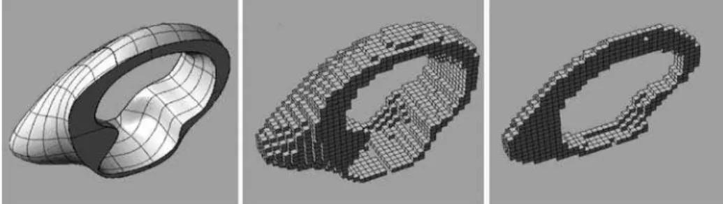
Fig. 1.Voxelized NURBS-based geometries provide a discrete 3D-space, which can be easily populated with Functional Objects.
Voxelized spaces in architecture enable fluent transition from curvilinear-smooth to angular-facetted geometries, and can be seen as mass-models used for volumetricaland functional studies: In an iterative process volumes are assigned to functions, and spatial relationships are established between the different func-tional volumes in order to generate 3D-layouts.
Voxelization within this project enables continuous, low-high resolution voxel-representation within a 5-90 cm range.
A number of FOs, representing objects, which can be placed within these voxels, are defined. Furthermore, constraints and optimization targets, which define how objects may be placed in voxel-space, are defined. These are then summarized in a problem description, which is translated into a SAT solver-understandable format. Finally, the solver produces numerical and graphical output containing all possible and optimal solutions found.
In this context, several constraint rules have been identified: 1. Cardinality constraints, describing how many FOs may be present; 2. Occupancy constraints, describing which voxels FOs may occupy; 3. Adjacency constraints, describing FOs neighboring rules, and 4. Design constraints, describing spatial relations between FOs. Furthermore, implicit overlap constraints exist, preventing FOs from overlapping.
After defining these constraints, a number of optimization goals have been formulated, including their priority: 1. Maximize occupancy: As many voxels as possible must be occupied by FOs, ensuring a maximum use of available space, and 2. Ergonomic optimization, describing optimizations that help create an optimal work flow, and/or ensure safety for people using the FOs.
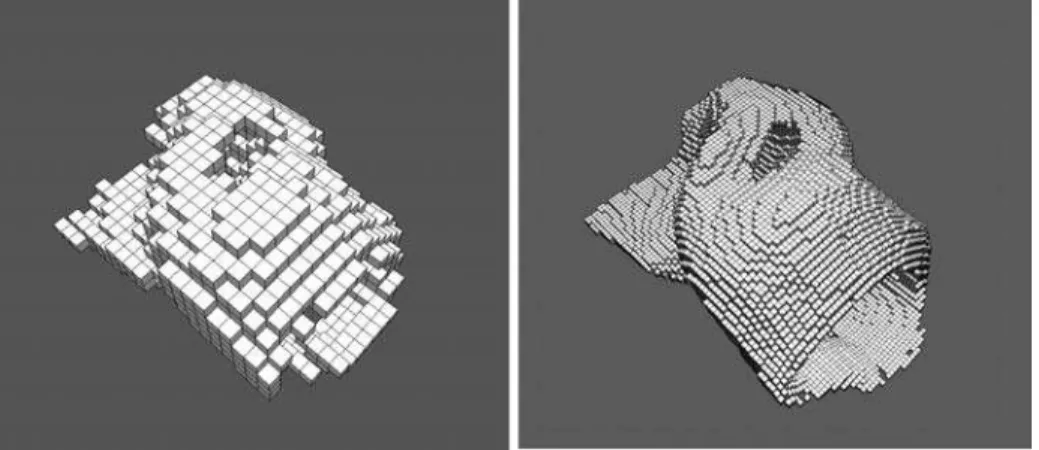
Fig. 2.Voxelization resolution ranges from 5-90 cm enabling an almost accurate rep-resentation of the curved geometry. Figure shows voxelization resolution 30/30/30 and 15/15/15 cm.
3
Implementation
The constraint solver used for solving the described layout-problem isMiniSat+. This solver employs DPLL SAT, which is a complete search procedure to explore a search space for possible solutions. This search procedure has been developed in the early 1960s and is referred to as the Davis-Putnam-Logemann-Loveland [DPLL] algorithm.
The DPLL algorithm divides a problem into sub-problems by selecting in each step a Boolean decision variable. This variable is assigned a truth value. The formula is then reduced under this assumption and checked for solutions. When a solution is found, the algorithm halts. When no solution is found, it can be concluded the variable should be assigned the opposite truth value and the search is continued. Only when the whole search space has been explored and no solution is found, the problem can be considered unsatisfiable.
Over the last decade relevant improvements have been made in order to speed up the DPLL algorithm: Most notably clause learning, as well as improved data structures and alternative types of backtracking have increased search efficiency enabling solvers to handle problems with millions of variables and clauses [8]. 3.1 Problem Description
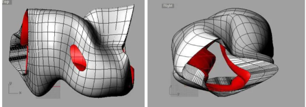
The layout-problem addresses NURBS-based designs tested in a case study, a foodkiosk - Figure 3 - which has been abstracted in a first iteration in such a way that equipment components are placed in a voxelized kiosk-space with a resolution of 90/90/90 cm.
In this context,FunctionLayouter 90[FL90] uses heuristics such as placement of equipment on two levels easily accessible to the kiosk-users 0.00-0.90 and 0.90-1.80 m in order to reduce effectively the search space. Furthermore, equipment
is defined as 90/90/90 cm units, ensuring a 1:1 mapping of FO to voxel, which is a simplified model.
The second iteration,Flexible FunctionLayouter[FlexFL] drops the 1:1 map-ping constraints, allowing FOs to span multiple voxels. This enables, inter alia, flexible voxel resolutions, which have been tested on a 30/30/30 cm resolution case study wherein FOs can span multiple voxels, increasing complexity in FO allocation with respect to geometry.
Fig. 3.Image showing top- and right-view of the kiosk as a 3D NURBS-model, which has been employed in the voxelization and layout study.
In the original FL90 test case, a food kiosk has been modeled, in which a total number of 14-26 functional objects have been assigned to 26 voxels. In this context, 11 functional object types have been differentiated: Refrigerator [RF], sink [SK], stove [ST], exhaust [EX], automat [AT], storage room [SR], trash bin [TB], dish-washer [DW], coffee machine [CM], micro-wave [MW], and cash desk [CD]. These FOs represent a typical equipment selection for a food-kiosk.
In addition, allocation constraints have been formulated implying definition of most effective functional spatial configurations: These are in part based on empirical findings formalized by Neufert [9] as well as the kitchen work-triangle defined by the Building Research Council [10] at the University of Illinois. This specifies that SK, ST, and RF form, preferably, a triangle in which the closer the length of the triangle sides is to about 200 cm, the better is the layout.
TheFlexFLtest-case uses a higher resolution model 30/30/30 cm, which im-plies a higher accuracy in geometrical representation, and therefore, a reduction of available space for placing FOs.
Instead of 14-26 FOsFlexFL30allocates 10 FOs with differentiated sizes de-fined by their corresponding height/width/depth: SK 60/60/30, ST 60/60/15, RF 60/60/60, AT 60/60/60, SR 60/60/60, MW 45/45/45, DW 45/45/45, TB 45/45/60, EX 45/45/15, CM 45/45/15, and CD 45/45/15. Sizes are, in this case, simplified but realistic assumption for FO-masses.
FlexFL30deals, therefore, with a nearly realistic problem description, while FL90 deals with an abstracted one.
3.2 Software Architecture
The basic control flow of FunctionLayouter has been split into a sequence of operations: Initially, a problem is read in from an XML problem description. Here, the problem is split into a number of rules and optimization targets.
The problem is then translated pseudo-Boolean constraints, which are run through a version ofMiniSat+modified by the authors of this paper.
The SAT solver’s output is then parsed and translated into solutions. Based on the optimization target, new constraints may then be added, andMiniSat+ invoked again. Finally, the solutions are displayed on a graphical user inter-face, where the user may request more information on a specific solution, again invoking the constraint translation system.
In this context, the main focus has been the translation of constraints from the specifications as given by designer, to the pseudo-Boolean constraints solv-able by MiniSat+.
3.3 Constraints Translation in FL90
In order to enable constraints translation into pseudo-Boolean, variables have been defined as Xx,y,zFO , where x, y, z are the coordinates in voxel-space. For
example, whenXRF
0,0,1is true, a refrigerator is placed at (0,0,1). When it is false, the refrigerator is not placed there.
These variables can then be combined into constraints. For example, an over-lap constraint specifying that only one item may be contained in voxelx, y,z would take on the form:
X
f∈FO
+1·Xx,y,zf ≤1 (3)
where FO is the set of all FOs that may be placed atx, y,z.
1. Cardinality and occupancy constraints are relatively trivial to translate, and are summations of possible locations for each FO, constrained by the min-imum and maxmin-imum number of instantiations of each FO. The occupancy con-straints are implicitly formulated in this manner, since all placement variables for a functional object are specified.
For example, to specify a maximum of two refrigerators [RF]:
X
x,y,z∈VOXRF
+1·XRFx,y,z≤2 (4)
where VOXRF contains all RF locations.
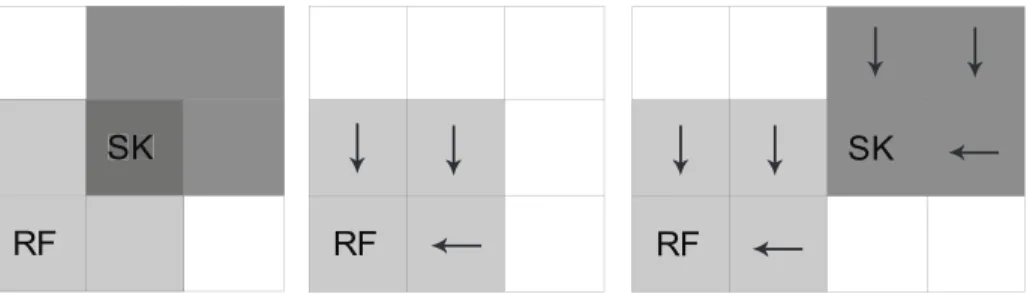
2. Adjacency rules are based on direct neighbors at the same height, not including diagonals. To compute such rules for an FOf at voxelx,y,z, a list of disallowed neighbor types is generated. Next, for every disallowed neighbor type, a list of voxels neighboringf is generated. This is the set of directly neighboring voxels, as in Figure 5(a). Once this neighbor list has been generated, FlexFL
RF
RF
RF
SK
SK
RF
SK
Fig. 4. Diagram showing occupancy constraint definition: (a) Invalid Overlap, (b) Marking using arrows, (c) Potential Neighbor inFlexFL.
iterates through these neighbors, and generates the following constraints for every voxelu,v,win the list:
+1·Xx,y,zf + 1·X g
u,v,w≤1 (5)
whereg is the current disallowed neighbor.
For the example given in Figure 5(a), the following constraints would be generated: +1·XRF 1,1 + 1·X SK 0,1 ≤1 +1·XRF 1,1 + 1·X SK 1,0 ≤1 +1·XRF 1,1 + 1·X SK 2,1 ≤1 +1·XRF 1,1 + 1·X SK 1,2 ≤1 (6)
3. Design constraints incorporate rules such as ‘if a sink is placed, a dish-washer must be placed in one of its neighboring cells’. In general, if an FO g must be placed next to an FO f, a neighbor list Lf
x,y,z is generated for every
voxelx,y,zthatf can be placed at as in the previous section. Unlike the normal adjacency case, however, the variables in the neighbor list are summed up, and included in a rule as follows:
−1·Xx,y,zf
X
u,v,w∈Lfx,y,z
+1·Xu,v,wg ≥0 (7)
This implies that iff is positioned atx,y,z, one of the voxels in Lf
x,y,z must
containg.
Constraints translation inFlexFL is different from FL90 mainly because the 1:1 mapping between voxels and FOs is replaced by a flexible mapping of FOs of different sizes to voxel resolutions ranging from 5-90 cm.
RF RF
Fig. 5.Diagram showing neighboring rules: (a) Neighbors inFL90 (b) 2x2 sized
neigh-bors inFlexFL.
3.4 Constraints Translation in FlexFL
A major difference between theFL90 andFlexFLis that a placement variable no longer represents the whole functional object, but the anchorof an FO, i.e. the
FOs voxel that is closest to the left, front, bottom corner of the FO.
Most constraints are based on this anchor voxel, including the cardinality constraints, occupancy constraints, and the optimizations that are explained in the next section. This allows the translation for these rules to constraints to remain unchanged. There are, however, a few differences, which are explained in this section.
1. Overlap constraints are more complex, to prevent situations such as in Figure 4(a). To prevent this from taking place, rules are added to ensure that if a certain voxel is occupied by the anchor of an FO, the other voxels occupied by it are marked with arrows to such an anchor voxel, as in Figure 4(b).
By ensuring that different arrows can not co-exist with each other or other occupying FOs in a single voxel, overlap is prevented. Extension to the 3D-case is done by adding a third, downwards pointer.
2. Adjacency rules are translated in a similar fashion to theFL90 case, how-ever, since in the FlexFL case, layouts as in Figure 4(c) are also possible. The neighbor list calculation is, therefore, performed differently. For example, the generated neighbor list for a 2x2 object would be as shown in Figure 5(b).
3.5 Optimization
Once the search space has been reduced by the above constraints, optimal solu-tions are generated from the number of valid solusolu-tions.
In bothFL90 andFlexFL, two optimization targets have been consecutively allowed, one to maximize the occupancy, and one to optimize spatial layout with
respect to ergonomic aspects. The maximization goal is applied during an initial invocation of the SAT solver.
A second call is then made to the SAT solver, with an additional constraint that fixates the occupancy to the previously found maximum value. During this run, an ergonomic target is used, based on the empirical findings formalized, inter alia, in the kitchen work triangle by the Building Research Council [10].
1. Maximizing Occupancy:MiniSat+contains a feature, which minimizes a given goal function. By summing up all possible FO locations, and multiplying this sum by -1, the following minimizing goal function is obtained:
−1· X
x,y,z∈VOX X
f∈FOx,y,z
Xx,y,zf (8)
where VOX contains all voxel positions, and FOx,y,z contains all FOs that can
be placed at that voxel position. The procedure that MiniSat+uses to find the optimal solution is to find an initial solution while ignoring the minimization function. It then computes the value of the goal function, and adds a constraint that all new solutions should be better. The solver then continues its search with this new constraint. This procedure is repeated until no new results are found, where the last result is the optimal one.
2. Ergonomic Rules: Since translating the kitchen work triangle target to a pseudo-Boolean goal function would be complex, a different approach has been chosen. An exhaustive search is performed for all different layouts of the sink, stove and refrigerator. This is done by running the solver repeatedly, while adding constraints to exclude sink-stove-refrigerator configurations that have previously been found.
These configurations are then presented to the user, ordered by their simi-larity with the optimal kitchen work triangle. The user can then select one of these configurations and generate all possible layouts containing that triangle configuration.
3.6 Results
FL90 generates 11 possible layout solutions from which 4 are optimal. All 4 optimal solutions satisfy occupancy maximization as well as SK, ST, and RF triangle optimization.
Generated solutions have been 2D visualized as shown in Figure 6. The tri-angle spanning between SK, ST, and RF shows the difference between possible and best possible solutions according to the principle the smaller the triangle, the better the solution.
FlexFL30generates 28 layout solutions incorporating about 23 different tri-angle configurations from which all are sub-optimal, since the maximum tritri-angle edge length is exceeding 391 cm. However, 9 triangle configurations are close to optimal.
Solutions are 2D represented in a sequence of voxel-layers, where FO positions are obviously more differentiated in response to not only the complex geometry
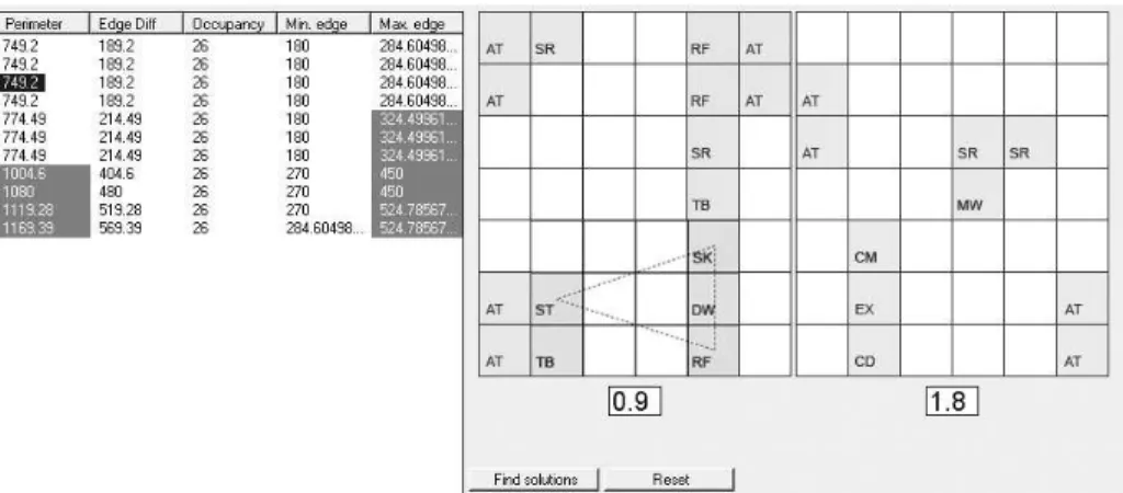
Fig. 6.Image shows one of the four optimal layouts for 90/90/90 voxelization resolution as 2D representation of the levels at 0.90 and 1.80 m relative space height. Sub-optimal solutions are marked in the table dark gray.
but also to a nearly realistic problem definition. Each voxel-layer shows contained FOs: TB for instance spans 2 voxel-layers, since it is 60 cm high, while SK occupies one voxel-layer, since only 30 cm high.
FOs are placed in such a way that they accommodate the complex geometry except for one case, where an AT is not accessible. This problem can be addressed by defining additional constraints describing in more detail spatial accessibility. However, FOs layout satisfies, in general, requirements of not only accessibility but also optimal placement relative to each other as well as to the whole space.
4
Discussion
FunctionLayoutergenerates, in comparison withLoosandWright, functional lay-outs of similar scale and realistic relevance. However,LoosandWrightdeal only with the placement of functional objects in 2D, whileFunctionLayouteraddresses the layout in 3D dealing with the allocation of functions within complex - free-formed geometries - instead of simple - rectangular - space geometries.
With respect to optimization,Loosconstructs solutions incrementally, testing intermediate solutions on consistency and other criteria relevant for architectural design, while optimization is carried out according to these intermediate tests, in an ad hoc procedure implying that no overall objective directs the search. However, without invoking a backtracking procedure, Loos search is not com-plete. As presented in Flemings paper [1] it is neither exhaustive nor does it yield solutions with an overall optimal objective.
Wrightis more similar to the approach presented in this paper:Wrightuses Constraint Satisfaction, to implement a backtracking procedure that makes the search complete. Optimization is implemented afterwards and is, therefore, not used to direct the search.
0.00 m AT AT AT RF TB DW SR SR TB AT AT AT 0.30 m AT AT AT ST RF TB DW SR SR SK TB AT AT AT 0.60 m AT AT AT AT ST CD SR SR CM MW AT SR SK AT AT AT AT 0.90 m AT AT CD SR SR CM MW AT AT 1.20 m AT AT EX SR SR MW AT AT 1.50 m
Fig. 7.Image shows layout solutions for 30/30/30 voxelization resolution as 2D repre-sentation of levels 0.90 - 1.80 m relative space height.
LoosandWrightdeal directly with the geometric aspects of both space and objects, whileFLemploys voxelization after which all geometric aspects are mod-eled through neighboring constraints. Furthermore,FLallows for a hierarchical optimization procedure: Optimal occupancy is an overall objective directing the search while the triangle objective is done by inspection and selection.
Loos and Wright as presented in Flemings paper [1], are rather sensitive to scaling effects, while FlexFL30 indicates that the approach presented in this paper is less sensitive with respect to scaling. Furthermore, sinceFL is able to find if an assignment is possible or not, theFL-search is complete.
5
Conclusion
FunctionLayouter generates functional layouts exhaustively and enables the de-signer to consider more alternatives than by means of conventional sketching methods mainly because architectural space planning is highly combinatorial and, therefore, difficult to conceive exhaustively by human search means.
Instead of one,FunctionLayoutergenerates all possible designs and allows for critical choices by departing from a singular design principle, that represents a potentially prejudiced position of the singular designer.FunctionLayouter gener-ates not only all possible solutions but also offers solutions within the spectrum of an optimal solutions-field.
Acknowledgments
This project has benefited, inter alia, from the contribution of Roland Schmehl and David Rutten.
References
1. Flemming U. et al.: Hierarchical Generate and Test vs. Constraint-Directed Search - A Comparison in the Context of Layout Synthesis published in Artificial Intelli-gence in Design, Kluwer Academic Publishers, Dordrecht (1992).
2. Michalek, J. J. et al.: Architectural Layout Design Optimization, Engineering Op-timization, Taylor and Francis, UK (2002).
3. Cook S. A.: The Complexity of Theorem-proving Procedures, Proceedings of the Third Annual ACM Symposium on theory of Computing, ACM Press, New York (1971).
4. Een N. and Sorensson N.: An Extensible SAT solver, Satisfiability Workshop (2003).
5. Pipatsrisawat, K. and Darwiche, A.: RSat 2.0: SAT Solver Description, Technical report D153, Automated Reasoning Group, Computer Science, Los Angeles (2007). 6. Heule M.J.H. and Maaren H. van: March dl: Adding Adaptive Heuristics and a New Branching Strategy published in Journal on Satisfiability, Boolean Modeling and Computation 2 (2006).
7. Bier H. et al.: Prototypes for Voxelized Representation in Architecture, AA 2006-2007, Delft (2007).
8. Lintao Z. and Sharad M.: The Quest for Efficient Boolean Satisfiability Solvers, LNCS, Springer Berlin/Heidelberg (2002).
9. Neufert E. and Neufert P.: Architects’ Data, Blackwell Science, 3Rev. Ed., UK Edition (2002).
10. Building Research Council: Kitchen Planning Standards, University of Illinois, Urbana- Champaign (1993).